
Subscribe to Our Youtube Channel
Related Manuals for Siemens SIMATIC NET RUGGEDCOM RS920L


Summary of Contents for Siemens SIMATIC NET RUGGEDCOM RS920L
- Page 1 Installation Manual SIMATIC NET Rugged Ethernet Switches RUGGEDCOM RS920L Edition 02/2020 https://www.siemens.com...
- Page 2 Preface Introduction Installing the Device SIMATIC NET Device Management Rugged Ethernet Switches RUGGEDCOM RS920L Communication Ports Technical Specifications Installation Manual Certification 02/2020 C79000-G8976-1032-06...
- Page 3 Note the following: WARNING Siemens products may only be used for the applications described in the catalog and in the relevant technical documentation. If products and components from other manufacturers are used, these must be recommend- ed or approved by Siemens. Proper transport, storage, installation, assembly, commissioning, operation and maintenance are required to ensure that the products operate safely and without any problems.
-
Page 4: Table Of Contents
Accessing Documentation ....................... v Disclaimer of Liability ......................v Registered Trademarks ......................v Training ..........................vi Customer Support ........................vi Contacting Siemens ....................... vii Introduction ........................... 1 Feature Highlights ....................1 Description ......................2 Required Tools and Materials ................. 4 Decommissioning and Disposal ................ - Page 5 Table of Contents Technical Specifications ...................... 27 Power Supply Specifications ................27 Failsafe Alarm Relay Specifications ..............28 Supported Networking Standards ................ 28 Copper Ethernet Port Specifications ..............28 Serial Port Specifications ..................29 Operating Environment ..................29 Mechanical Specifications ..................29 Dimension Drawings ...................
-
Page 6: Preface
However, deviations between the product and the documentation may exist. Siemens shall not be liable for any errors or omissions contained herein or for conse- quential damages in connection with the furnishing, performance, or use of this ma- terial. -
Page 7: Training
Siemens Sales representative. Customer Support Customer support is available 24 hours, 7 days a week for all Siemens customers. For technical support or general information, contact Siemens Customer Support through any of the following methods: Online Visit http://www.siemens.com/automation/support-request... -
Page 8: Contacting Siemens
Preface Contacting Siemens Contacting Siemens Address Siemens AG Industry Sector 300 Applewood Crescent Concord, Ontario Canada, L4K 5C7 Telephone Toll-free: 1 888 264 0006 Tel: +1 905 856 5288 Fax: +1 905 856 1995 E-Mail ruggedcom.info.i-ia@siemens.com https://www.siemens.com RUGGEDCOM RS920L Installation Manual, 02/2020, C79000-G8976-1032-06... - Page 9 Preface Contacting Siemens viii RUGGEDCOM RS920L Installation Manual, 02/2020, C79000-G8976-1032-06...
-
Page 10: Introduction
Introduction The RUGGEDCOM RS920L is a utility-grade serial device server and managed Ether- net switch supporting Ethernet over VDSL (EoVDSL). The RUGGEDCOM RS920L can be configured with two serial ports (RS485/RS422/RS232) and up to EoVDSL ports. EoVDSL supports LAN segments of up to 5 km (3.1 mi) over telephone grade cable (or other legacy serial cabling) at up to 35 Mbps (upstream and downstream). -
Page 11: Description
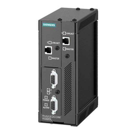
Introduction 1.2 Description • Up to 5 km (3.1 mi) LAN segments • Asymmetric data rates up to 40 Mbps • Automatically selects fastest data rate based on distance and quality of cable • Software selectable to be master or slave •... - Page 12 Introduction 1.2 Description POWER LED ALARM LED EoVDSL Ports Serial Ports RS232 Console Port (Serial) Failsafe Alarm Relay Chassis Ground Connection Power Supply Terminal Block Figure 1.1 RUGGEDCOM RS920L POWER LED Illuminates green when power is supplied to the device. ALARM LED Illuminates red when an alarm condition exists.
-
Page 13: Required Tools And Materials
Siemens also does not recommend using copper Ethernet ports to interface with de- vices in the field across distances that could produce high levels of ground potential rise (i.e. -
Page 14: Installing The Device
This product contains no user-serviceable parts. Attempted service by unauthorized personnel shall render all warranties null and void. Changes or modifications not expressly approved by Siemens AG could invalidate specifications, test results, and agency approvals, and void the user's authority to operate the equipment. -
Page 15: Installing The Device In Hazardous Locations
2.2 Installing the Device in Hazardous Locations Verify all items are included. NOTICE If any item is missing or damaged, contact Siemens for assistance. Installing the Device in Hazardous Locations The RUGGEDCOM RS920L is designed to comply with the safety standards for Class I, Division 2 hazardous locations where concentrations of flammable gases, vapors or liquids may be present, as opposed to normal operating environments. -
Page 16: Mounting The Device
Installing the Device 2.3 Mounting the Device Mounting the Device The RUGGEDCOM RS920L is designed for maximum mounting and display flexibility. It can be equipped with adapters that allow it to be attached to a DIN rail or panel. IMPORTANT Heat generated by the device is channeled outwards from the enclosure. As such, it is recommended that 2.5 cm (1 in) of space be maintained on all open sides of the device to allow for some convectional airflow. - Page 17 Installing the Device 2.3.1 Mounting the Device on a DIN Rail Mounting the Device To mount the device to a DIN rail, do the following: Hook the top teeth of the adapter onto the DIN rail. Note The adapter features a sliding release with a slot at the bottom for a flathead screwdriver.
-
Page 18: Mounting The Device To A Panel
Installing the Device 2.3.2 Mounting the Device to a Panel Removing the Device To remove the device from a DIN rail, do the following: Insert a flathead screwdriver into the slot of the sliding release and move it down. DIN Rail DIN Rail Adapter Figure 2.2 Removing the Device from a DIN Rail... -
Page 19: Connecting The Failsafe Alarm Relay
Installing the Device 2.4 Connecting the Failsafe Alarm Relay Place the device against the panel and align the adapters with the mounting holes. Screw Panel Mount Adapter Figure 2.3 Panel Mounting Secure the adapters to the panel with #6-32 screws. Connecting the Failsafe Alarm Relay The failsafe relay can be configured to latch based on alarm conditions. -
Page 20: Connecting Power
Installing the Device 2.5 Connecting Power Connect a failsafe device to the terminal block. Normally Closed Common Normally Open Figure 2.4 Failsafe Alarm Relay Wiring Connecting Power The RUGGEDCOM RS920L supports power input from a single high AC/DC or low DC power supply. IMPORTANT •... -
Page 21: Connecting High Ac/Dc Power
Installing the Device 2.5.1 Connecting High AC/DC Power 2.5.1 Connecting High AC/DC Power To connect a high AC/DC power supply to the device, do the following: NOTICE Electrical hazard – risk of damage to equipment Do not connect AC power cables to terminals for DC power. Damage to the power supply may occur. - Page 22 Installing the Device 2.5.1 Connecting High AC/DC Power Connect the positive wire from the power source to the positive/live (+/L) termi- nal on the terminal block. Positive/Live (+/L) Terminal Negative/Neutral (-/N) Terminal Surge Ground Terminal Braided Ground Cable Figure 2.5 Terminal Block Wiring RUGGEDCOM RS920L Installation Manual, 02/2020, C79000-G8976-1032-06...
-
Page 23: Connecting Low Dc Power
Installing the Device 2.5.2 Connecting Low DC Power ± ± ± ± Positive Terminal Negative Terminal Surge Ground Terminal Braided Ground Cable Figure 2.6 Terminal Block Wiring – Dual DC Power Supply Inputs Connect the negative wire from the power source to the negative/neutral (-/N) terminal on the terminal block. - Page 24 Installing the Device 2.5.2 Connecting Low DC Power Connect the positive wire from the power source to the positive terminal on the terminal block. ± ± Positive Terminal Negative Terminal Surge Ground Terminal Braided Ground Cable Figure 2.7 Terminal Block Wiring – Single DC Power Supply Inputs Connect the negative wire from the power source to the negative terminal on the terminal block.
- Page 25 Installing the Device 2.5.2 Connecting Low DC Power [Optional] If a redundant connection is required, repeat Step 2 Step 3 connect the secondary power inputs. ± ± ± ± Positive Terminal Negative Terminal Surge Ground Terminal Braided Ground Cable Figure 2.8 Terminal Block Wiring – Dual DC Power Supply Inputs Using a braided wire or other appropriate grounding wire, connect the surge ground terminal to the chassis ground connection.
-
Page 26: Device Management
Device Management This section describes how to connect to and manage the device. Connecting to the Device The following describes the various methods for accessing the RUGGEDCOM RS920L console and Web interfaces on the device. For more detailed instructions, refer to the RUGGEDCOM RS920L User Guide for the RUGGEDCOM RS920L. -
Page 27: Configuring The Device
Device Management 3.2 Configuring the Device The serial console port implements RS232 DCE (Data Communication Equipment) on a DB9 connector. The following is the pin-out for the port: Name Description Reserved (Do Not Connect) Transmit Data Receive Data Reserved (Do Not Connect) Signal Ground Reserved (Do Not Connect) Reserved (Do Not Connect) -
Page 28: Communication Ports
Communication Ports The RUGGEDCOM RS920L can be equipped with various types of communication ports to enhance its abilities and performance. Ports 1 and 2 Port 3 Port 9 Figure 4.1 Port Assignment Port Type 1 and 2 Serial Ports 3 and 9 EoVDSL Ports EoVDSL Ports Ethernet over VDSL (EoVDSL) connections operate in pairs with one device config-... - Page 29 4.1 EoVDSL Ports from the Master to the Slave is designated downstream, while data flowing from the Slave to the Master is designated upstream. Siemens supports two types of EoVDSL: • Universal EoVDSL Universal EoVDSL ports are Master/Slave selectable and offer symmetric data rates (upstream and downstream) up to 35 Mbps.
-
Page 30: Eovdsl Wiring
Communication Ports 4.1.1 EoVDSL Wiring Description Reserved (Do Not Connect) Reserved (Do Not Connect) Ring Figure 4.2 EoVDSL RJ11 Modem Port Reserved (Do Not Connect) Reserved (Do Not Connect) 4.1.1 EoVDSL Wiring VDSL operates over 2-wire Category 3 (CAT-3) or higher twisted-pair wiring. Other twisted-pair wiring with similar characteristics may work, although the performance will vary depending on the cable characteristics and distance. -
Page 31: Eovdsl Performance
Communication Ports 4.1.3 EoVDSL Performance Long-Reach EoVDSL port, no Master/Slave configuration is necessary, since the ports will already be fixed as Master or Slave. Once configured and connected together, each device will attempt to achieve the maximum speed based on the line length and conditions. The RUGGEDCOM RS920L's Link/Act LED may flash on and off several times before setting on a final link speed and declaring the port up. -
Page 32: Serial Ports
Communication Ports 4.2 Serial Ports Universal EoVDSL Performance Characteristics On No. 24 AWG Polyethylene Insulated Cable (PIC) twisted-pair wiring, the following performance is typical with Universal EoVDSL: Distance Downstream/Upstream (Mbps) 0.5 km (1640 ft) 0.6 km (1969 ft) 0.7 km (2297 ft) 0.9 km (2953 ft) 1.0 km (3280 ft) 1.3 km (4265 ft) -
Page 33: Serial Rs232/Rs485/Rs422 Db9 Ports
Communication Ports 4.2.1 Serial RS232/RS485/RS422 DB9 Ports State Description No link detected For specifications on serial ports, refer to "Serial Port Specifications (Page 29)". 4.2.1 Serial RS232/RS485/RS422 DB9 Ports The RS920L can be equipped with serial RS232/RS485/RS422 DB9 ports. Each port can be set individually through the RUGGEDCOM RS920L operating system to oper- ate in RS232, RS485 or RS422 mode. -
Page 34: Serial Rs232/Rs485/Rs422 Fiber Ports
Communication Ports 4.2.3 Serial RS232/RS485/RS422 Fiber Ports The following is the pin-out description for the RS232/RS485/RS422 RJ45 ports: Name RS232 RS485 RS422 Mode Mode Mode DSR/RI Figure 4.4 RS232/RS485/RS422 RJ45 Ser- ial Console Port Common (Isolated) Ground ... - Page 35 Communication Ports 4.2.4 Connecting Multiple RS485 Devices • The number of devices wired should not exceed 32, and total distance should be less than 1219 m (4000 ft) at 100 kbps. • The Common terminals should be connected to the common wire inside the shield.
-
Page 36: Technical Specifications
Technical Specifications This section provides important technical specifications related to the device. Power Supply Specifications Note When determining cable lengths, make sure the minimum input voltage for the pow- er supply is provided at the power source. Hazardous Environments Power Sup- Input Range Internal Isolation... -
Page 37: Failsafe Alarm Relay Specifications
Technical Specifications 5.2 Failsafe Alarm Relay Specifications Failsafe Alarm Relay Specifications Hazardous Environments Maximum Switching Voltage Rated Switching Current Isolation 30 VDC 1500 V for 1 minute 80 VDC 0.3 A 30 VAC Non-Hazardous Environment Maximum Switching Voltage Rated Switch- Isolation ing Current 30 VDC 2 A, 60 W... -
Page 38: Serial Port Specifications
Technical Specifications 5.5 Serial Port Specifications Typical distance. Dependent on the number of connectors and splices. RMS 1 minute. Serial Port Specifications The following details the specifications for serial ports that can be ordered with the RUGGEDCOM RS920L. Copper Serial Ports Baud Rate 300 to 230 kbps Connector... -
Page 39: Dimension Drawings
Technical Specifications 5.8 Dimension Drawings Dimension Drawings Note All dimensions are in millimeters, unless otherwise stated. 65.3 116.59 7.87 Figure 5.1 Overall Dimensions RUGGEDCOM RS920L Installation Manual, 02/2020, C79000-G8976-1032-06... - Page 40 Technical Specifications 5.8 Dimension Drawings 127.3 13.64 101.6 11.2 78.74 120.65 Figure 5.2 Panel and DIN Rail Mount Dimensions RUGGEDCOM RS920L Installation Manual, 02/2020, C79000-G8976-1032-06...
- Page 41 Technical Specifications 5.8 Dimension Drawings RUGGEDCOM RS920L Installation Manual, 02/2020, C79000-G8976-1032-06...
-
Page 42: Certification
Certification The RUGGEDCOM RS920L device has been thoroughly tested to guarantee its confor- mance with recognized standards and has received approval from recognized regula- tory agencies. Approvals This section details the standards to which the RUGGEDCOM RS920L complies. 6.1.1 This device meets the requirements of the following Canadian Standards Association (CSA) standards under certificate 1550963: •... -
Page 43: Fcc
Title 21 Code of Federal Regulations (CFR) – Chapter I – Sub-chapter J – Radiolog- ical Health 6.1.4 ISED This device is declared by Siemens AG to meet the requirements of the following ISED (Innovation Science and Economic Development Canada) standard: • CAN ICES-3 (A)/NMB-3 (A) 6.1.5... -
Page 44: Acma
6.1.7 RoHS This device is declared by Siemens AG to meet the requirements of the following Ro- HS (Restriction of Hazardous Substances) directives for the restricted use of certain hazardous substances in electrical and electronic equipment: •... -
Page 45: Emc And Environmental Type Tests
Certification 6.2 EMC and Environmental Type Tests EMC and Environmental Type Tests The RUGGEDCOM RS920L has passed the following Electromagnetic Compatibility (EMC) and environmental tests. EMC Type Tests Test Description Test Levels Severi- ty Levels Enclosure ± 8 kV 61000-4-2 Contact Enclosure Air ±... - Page 46 Certification 6.2 EMC and Environmental Type Tests Test Description Test Levels Severi- ty Levels 1 kV Differential Mode @ 1 MHz Mains Frequency Voltage Signal Ports 30 V Continuous 61000-4-16 300 V for 1 s DC Pow- 30 V Continuous er Ports 300 V for 1 s Ripple on DC Power Supply DC Pow-...
- Page 47 Certification 6.2 EMC and Environmental Type Tests Description Test Levels AC Power Ports 5 kV Dielectric Strength Signal Ports 2 kV (Failsafe Relay) DC Power Ports 2 kV AC Power Ports 2 kV Environmental Type Tests Test Description Test Levels Severity Levels IEC 60068-2-1 Cold Temperature Test Ad...
- Page 48 Further Information Siemens RUGGEDCOM https://www.siemens.com/ruggedcom Industry Online Support (service and support) https://support.industry.siemens.com Industry Mall https://mall.industry.siemens.com Siemens AG Digital Industry Process Automation Postfach 48 48 90026 NÜRNBERG GERMANY...
Need help?
Do you have a question about the SIMATIC NET RUGGEDCOM RS920L and is the answer not in the manual?
Questions and answers