
Related Manuals for Siemens SIMATIC NET RUGGEDCOM RS900GF


Summary of Contents for Siemens SIMATIC NET RUGGEDCOM RS900GF
- Page 1 Installation Manual SIMATIC NET Rugged Ethernet Switches RUGGEDCOM RS900GF Edition 01/2021 https://www.siemens.com...
- Page 2 Preface Introduction Installing the Device SIMATIC NET Device Management Rugged Ethernet Switches RUGGEDCOM RS900GF Communication Ports Technical Specifications Installation Manual Certification 01/2021 C79000-G8976-1352-05...
- Page 3 Note the following: WARNING Siemens products may only be used for the applications described in the catalog and in the relevant technical documentation. If products and components from other manufacturers are used, these must be recommended or approved by Siemens. Proper transport, storage, installation, assembly, commissioning, operation and maintenance are required to ensure that the products operate safely and without any problems.
-
Page 4: Table Of Contents
Accessing Documentation ....................... v Registered Trademarks ......................v Warranty ..........................v Training ..........................vi Customer Support ........................vi Contacting Siemens ....................... vii Introduction ........................... 1 Feature Highlights ....................1 Description ......................2 Required Tools and Materials ................. 3 Decommissioning and Disposal ................3 Supported Fiber Optic Cables ................ - Page 5 Table of Contents Failsafe Alarm Relay Specifications ..............21 Copper Ethernet Port Specifications ..............22 Fiber Optic Ethernet Port Specifications ............... 22 Operating Environment ..................23 Mechanical Specifications ..................23 Dimension Drawings ................... 23 Certification ......................... 27 Approvals ......................27 6.1.1 CSA ........................
-
Page 6: Preface
Warranty Siemens warrants this product for a period of five (5) years from the date of purchase, conditional upon the return to factory for maintenance during the warranty term. This product contains no user-serviceable parts. Attempted service by unauthorized personnel shall render all warranties null and void. -
Page 7: Training
Siemens Sales representative. Customer Support Customer support is available 24 hours, 7 days a week for all Siemens customers. For technical support or general information, contact Siemens Customer Support through any of the following methods: Online Visit http://www.siemens.com/automation/support-request... -
Page 8: Contacting Siemens
Preface Contacting Siemens • Ask questions or share knowledge with fellow Siemens customers and the support community Contacting Siemens Address Siemens AG Industry Sector 300 Applewood Crescent Concord, Ontario Canada, L4K 5C7 Telephone Toll-free: 1 888 264 0006 Tel: +1 905 856 5288... - Page 9 Preface Contacting Siemens viii RUGGEDCOM RS900GF Installation Manual, 01/2021, C79000-G8976-1352-05...
-
Page 10: Introduction
Introduction The RUGGEDCOM RS900GF is an industrially hardened, fully managed Ethernet switch providing dual fiber optical Gigabit Ethernet ports and eight Fast Ethernet copper ports. Designed to operate reliably in harsh industrial environments, the RUGGEDCOM RS900GF provides a high level of immunity to electromagnetic interference and heavy electrical surges typical of environments found in electric utility substations, factory floors or in curb side traffic control cabinets. -
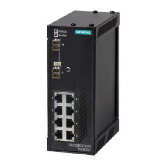
Page 11: Description
Introduction 1.2 Description Description The RUGGEDCOM RS900GF features various ports, controls and indicator LEDs on the front panel for connecting, configuring and troubleshooting the device. ALARM LED POWER LED Fiber Optic or SFP (Small Form-Factor Pluggable) Ethernet Ports Copper Ethernet Ports RS-232 Console Port (DB9) Failsafe Alarm Relay Power Supply Terminal Block... -
Page 12: Required Tools And Materials
Introduction 1.3 Required Tools and Materials Power Supply Terminal Block A pluggable terminal block. For more information, refer to: • "Connecting Power (Page 10)" • "Power Supply Specifications (Page 21)" Required Tools and Materials The following tools and materials are required to install the RUGGEDCOM RS900GF: Tools/Materials Purpose AC or DC power cord (16 AWG) -
Page 13: Tamper-Evident Security Seals
NOTICE Worn, damaged or missing seals must be replaced immediately. Replacement seals are available for purchase from Siemens. For more information, contact a Siemens Sales representative. There are three ways to determine if a security seal has been tampered with: •... -
Page 14: Installing The Device
Inspect the package for damage before opening it. Visually inspect each item in the package for any physical damage. Verify all items are included. IMPORTANT If any item is missing or damaged, contact Siemens for assistance. RUGGEDCOM RS900GF Installation Manual, 01/2021, C79000-G8976-1352-05... -
Page 15: Cabling Recommendations
Installing the Device 2.2 Cabling Recommendations Cabling Recommendations Siemens does not recommend the use of copper cabling of any length for critical, real-time substation automation applications. All copper Ethernet ports on RUGGEDCOM products include transient suppression circuitry to protect against damage from electrical transients and conform with IEC 61850-3 and IEEE 1613 Class 1 standards. - Page 16 Installing the Device 2.3.1 Mounting the Device on a DIN Rail Mounting the Device To mount the device to a DIN rail, do the following: Hook the top teeth of the adapter onto the DIN rail. Note The adapter features a sliding release with a slot at the bottom for a flathead screwdriver.
-
Page 17: 2.3.2 Mounting The Device To A Panel
Installing the Device 2.3.2 Mounting the Device to a Panel Removing the Device To remove the device from a DIN rail, do the following: Insert a flathead screwdriver into the slot of the sliding release and move it down. DIN Rail DIN Rail Adapter Figure 2.2 Removing the Device from a DIN Rail... - Page 18 Installing the Device 2.3.2 Mounting the Device to a Panel To mount the device to a panel, do the following: Loosen the screws for the panel adapters located at the top and bottom of the device. Panel Adapter Screw Figure 2.3 Installing the Panel Adapters For both adapters, align the slots with the screws and then slide the adapters onto the device.
-
Page 19: Connecting The Failsafe Alarm Relay
Installing the Device 2.4 Connecting the Failsafe Alarm Relay Using two #6-32 screws for each adapter, secure the device to the panel. Connecting the Failsafe Alarm Relay The failsafe relay can be configured to latch based on alarm conditions. The NO (Normally Open) contact is closed when the unit is powered and there are no active alarms. -
Page 20: Connecting High Ac/Dc Power
Installing the Device 2.5.1 Connecting High AC/DC Power • For 125/250 VDC rated equipment, an appropriately rated DC circuit breaker must be installed. • Use minimum #16 gage copper wiring when connecting terminal blocks. • Equipment must be installed according to applicable local wiring codes and standards. - Page 21 Installing the Device 2.5.1 Connecting High AC/DC Power Connect the positive wire from the power source to the positive/live (+/L) terminal on the terminal block. Positive/Live (+/L) Terminal Negative/Neutral (-/N) Terminal Surge Ground Terminal Braided Ground Cable Figure 2.6 Terminal Block Wiring Connect the negative wire from the power source to the negative/neutral (-/N) terminal on the terminal block.
-
Page 22: 2.5.2 Connecting Low Dc Power
Installing the Device 2.5.2 Connecting Low DC Power 2.5.2 Connecting Low DC Power To connect a power source to the low DC power supply, do the following: NOTICE Electrical hazard – risk of damage to equipment Before testing the dielectric strength (HIPOT) in the field, remove the braided ground cable connected to the surge ground terminal and chassis ground. - Page 23 Installing the Device 2.5.2 Connecting Low DC Power Connect the ground terminal on the power source to the chassis ground terminal on the device. If a redundant power source is required, repeat Step 1 Step 5 using the second terminal. RUGGEDCOM RS900GF Installation Manual, 01/2021, C79000-G8976-1352-05...
-
Page 24: Device Management
Device Management This section describes how to connect to and manage the device. Connecting to the Device The following describes the various methods for accessing the RUGGEDCOM RS900GF console and Web interfaces on the device. For more detailed instructions, refer to the RUGGEDCOM RS900GF User Guide for the RUGGEDCOM RS900GF. Serial Console Port Connect a PC or terminal directly to the serial console port to access the boot-time control and RUGGEDCOM ROS console interface. -
Page 25: Configuring The Device
Device Management 3.2 Configuring the Device The following is the pin-out for the port: Name Description Reserved (Do Not Connect) Transmit Data Receive Data Reserved (Do Not Connect) Signal Ground Reserved (Do Not Connect) Reserved (Do Not Connect) Reserved (Do Not Connect) Figure 3.1 Serial DB9 Console Port Reserved (Do Not Connect) -
Page 26: Communication Ports
Communication Ports The RUGGEDCOM RS900GF features eight standard 10/100Base-TX copper RJ45 Ethernet ports. It can also be equipped with two additional Gigabit Ethernet capable ports, for which many fiber transceiver and copper options are available. Each communication port type has a specific place in the RUGGEDCOM RS900GF chassis. -
Page 27: Fiber Optic Ethernet Ports
Communication Ports 4.2 Fiber Optic Ethernet Ports excessive noise and interference, but more importantly, create a potential shock hazard that can result in serious injury. LEDs Each port features an LED that indicates its link/activity state and current speed. Link LED Activity LED Figure 4.2 LED for RJ45 Ports (1 to 8) -
Page 28: Sfp Transceivers
SFP Transceivers The RUGGEDCOM RS900GF supports up to two Small Form-Factor Pluggable (SFP) transceiver sockets, which are compatible with a wide array of SFP transceivers available from Siemens. LEDs Each socket features an LED that indicates its link state. State... - Page 29 RUGGEDCOM SFP Transceiver Catalog [https:// support.industry.siemens.com/cs/ca/en/view/109482309]. IMPORTANT Only use SFP transceivers approved by Siemens for RUGGEDCOM products. Siemens accepts no liability as a result of performance issues related in whole or in part to third-party components. RUGGEDCOM RS900GF...
-
Page 30: Technical Specifications
Technical Specifications This section provides important technical specifications related to the device. Power Supply Specifications Hazardous Environments Power Input Range Internal Isolation Maximum Supply Type Fuse Rating Power Minimum Maximum Consumption 125 VDC 250 VDC 3.15 A(T) 4 kVAC 10 W 100 VAC 240 VAC 3.15 A(T) -
Page 31: Copper Ethernet Port Specifications
Note • Maximum segment length is greatly dependent on factors such as fiber quality, and the number of patches and splices. Consult a Siemens Sales associate when determining maximum segment distances. • All optical power numbers are listed as dBm averages. -
Page 32: Operating Environment
Technical Specifications 5.5 Operating Environment Cable Connector Tx λ Tx min Tx max Distance Mode Type Sensitivity Saturation Type (nm) (dBm) (dBm) (km) (μm) (dBm) (dBm) 50μ/125 -9.5 9μ/125 1310 -9.5 9μ/125 1310 9μ/125 1310 9μ/125 1310 Typical. Operating Environment The RUGGEDCOM RS900GF is rated to operate under the following environmental conditions. - Page 33 Technical Specifications 5.7 Dimension Drawings 65.1 116.6 Figure 5.1 Overall Dimensions RUGGEDCOM RS900GF Installation Manual, 01/2021, C79000-G8976-1352-05...
- Page 34 Technical Specifications 5.7 Dimension Drawings 129.9 101.6 11.2 13.7 78.7 120.7 Figure 5.2 Panel and DIN Rail Mount Dimensions RUGGEDCOM RS900GF Installation Manual, 01/2021, C79000-G8976-1352-05...
- Page 35 Technical Specifications 5.7 Dimension Drawings RUGGEDCOM RS900GF Installation Manual, 01/2021, C79000-G8976-1352-05...
-
Page 36: Certification
Certification The RUGGEDCOM RS900GF device has been thoroughly tested to guarantee its conformance with recognized standards and has received approval from recognized regulatory agencies. Approvals This section details the standards to which the RUGGEDCOM RS900GF complies. 6.1.1 This device meets the requirements of the following Canadian Standards Association (CSA) standards under certificate 1550963: •... -
Page 37: European Union (Eu)
Methods of Measurement The device is marked with a CE marking and can be used throughout the European community. A copy of the CE Declaration of Conformity is available from Siemens AG. For contact information, refer to "Contacting Siemens (Page vii)". -
Page 38: Fda/Cdrh
Title 21 Code of Federal Regulations (CFR) – Chapter I – Sub-chapter J – Radiological Health 6.1.5 ISED This device is declared by Siemens AG to meet the requirements of the following ISED (Innovation Science and Economic Development Canada) standard: • CAN ICES-3 (A)/NMB-3 (A) 6.1.6... -
Page 39: 6.1.8 Other Approvals
Certification 6.1.8 Other Approvals 6.1.8 Other Approvals This device meets the requirements of the following additional standards: • EN50121-4 Railway applications – Electromagnetic Compatibility – Emission and Immunity of the Signaling and Telecommunications Apparatus EMC and Environmental Type Tests The RUGGEDCOM RS900GF has passed the following Electromagnetic Compatibility (EMC) and environmental tests. - Page 40 Certification 6.2 EMC and Environmental Type Tests Test Description Test Levels Severity Levels 100% for 0.05 s AC Power 30% for 1 Period Ports 60% for 50 Periods Voltage Dips and Interrupts AC Power 100% for 5 Periods 61000-4-11 Ports 100% for 50 Periods Damped Oscillatory...
- Page 41 Certification 6.2 EMC and Environmental Type Tests Description Test Levels Earth Ground Ports ± 4 kV Oscillatory Signal Ports 2.2 kV Common Mode @ 1 MHz DC Power Ports 2.5 kV Common and Differential Mode @ 1 MHz AC Power Ports 2.5 kV Common and Differential Mode @ 1 MHz HV Impulse...
- Page 42 Further Information Siemens RUGGEDCOM https://www.siemens.com/ruggedcom Industry Online Support (service and support) https://support.industry.siemens.com Industry Mall https://mall.industry.siemens.com Siemens AG Digital Industry Process Automation Postfach 48 48 90026 NÜRNBERG GERMANY...
Need help?
Do you have a question about the SIMATIC NET RUGGEDCOM RS900GF and is the answer not in the manual?
Questions and answers