Table of Contents
Advertisement
Quick Links
Advertisement
Table of Contents

Related Manuals for Johnson Controls LE4000

Summary of Contents for Johnson Controls LE4000
- Page 1 LE4000/LE4000E LTE Wireless Alarm Communicator Installation Manual V5.X Warning: This manual contains information on limitations regarding product use and function and information on the limitations as to liability of the manufacturer. The entire manual should be carefully read.
-
Page 2: Table Of Contents
LE4000/LE4000E Installation Manual Table of Contents Section 1: Introduction 1.1 Features 1.2 Technical specifications Section 2: Identification of parts Section 3: Installing the LE4000/LE4000E Section 4: Connecting the LE4000/LE4000E Section 5: Status LEDs 5.1 Operating modes 5.2 Normal mode 5.3 Service mode Section 6: Operating principles 6.1 Simulated landline mode... - Page 3 P1 when used as single communication path or P2 when used as a back up in conjunction with a POTS line (dialer). The LE4000/LE4000E is also listed for Active line security levels A1-A4 (90 seconds heartbeat enabled and supervision window of 180s required at monitoring station receiver and encryption must be enabled).
- Page 4 LE4000/LE4000E Installation Manual installations, the LE4000/LE4000E must be connected to a ULC-listed power supply with a minimum of 24 hours standby power or powered using the ADP 1310(W)-NAU and a 2200mAh battery. Notes for using private, corporate and high speed data networks: Network access and domain access policies shall be set to restrict unauthorized network access, and “spoofing”or “denial of service”attacks.
-
Page 5: Section 1: Introduction
(25ft/7.6m) and LTE-50ANT (50ft/15.2m) are available. Note: The LE4000/LE4000E is designed to work with the Contact ID communication format as described in the SIA DC-05 stand- ard, as well as the SIA communications format as described in the SIA DC-03 standard. Before completing the field installation of the alarm monitoring system please ensure communication with the supervising central station is successful by sending several events and getting confirmation that they have been received. - Page 6 LE4000/LE4000E Installation Manual Peak current (with battery): 350mA* * Plus any curent draw from LE4000/LE4000E + ve terminal Battery: NiMH, rated 7.2V, 2.2Ah Battery charging voltage (maximum): 9.1V Battery charging current: 160mA Battery standby time: 24 hours NOTE: Battery must be replaced every 3-5 years.
-
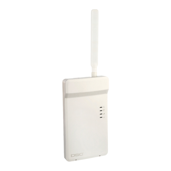
Page 7: Section 2: Identification Of Parts
Section 2: Identification of parts Section 2: Identification of parts Plastic casing Anchor screw holes (3mm) SIM card holder LTE radio module LTE external antenna* Antenna mounting hardware Wall tamper switch Cover tamper switch Status LEDs (see "Status LEDs" on page 12) PC-Link connector Battery connector Terminal blocks... -
Page 8: Section 3: Installing The Le4000/Le4000E
Blue/Green (Bottom) If the signal strength is too low (bottom signal LED off or flashing), the LE4000/LE4000E will move to Step 3 and scan for carriers with sufficient signal strength and attach to the carrier. If the LE4000/LE4000E is connected to a carrier with sufficient signal strength (minimum of bottom signal strength LED on solid), it will move to Step Step 2b –... - Page 9 Blue/Green (Top) Blue/Green (Bottom) FLASHING Once remote programming is completed, the blue LED will switch to solid and the LE4000/LE4000E will move to Step 5. Step 5 – Receiver initialization The red LED and the blue LED are both solid and the signal strength LEDs are off.
- Page 10 Step 6 - Mounting the LE4000/LE4000E Note: If using an LE4000/LE4000E trim plate, snap the LE4000/LE4000E back plate onto the trim plate before mounting to the wall. For flush mounting or using with an extension antenna, remove the provided breakaway from the trim plate prior to mounting.
-
Page 11: Section 4: Connecting The Le4000/Le4000E
Section 4: Connecting the LE4000/LE4000E Section 4: Connecting the LE4000/LE4000E TIP (1) / RNG (2) External telephone line - If the LE4000/LE4000E is being used as a back-up communicator, these terminals must be connected directly to the incoming telephone line. -
Page 12: Section 5: Status Leds
(Bottom) on an LTE channel, the LED is blue. If the LE4000/LE4000E is operating on a 3G channel, the LED is Green. If this LED is off and the Red LED is on, the wireless network service is unavailable (NO SERVICE). This LED flashes when wireless network reception is poor. -
Page 13: Service Mode
5.3 Service mode 5.3 Service mode To view detailed trouble information on the status LEDs, place the LE4000/LE4000E in Service mode by remov- ing the front cover. When in Service mode, the status LEDs indicate troubles as follows. Table 4-2 LED troubles... -
Page 14: Section 6: Operating Principles
LE4000/LE4000E will not switch during ongoing calls. Note: When the landline is down, the LE4000/LE4000E provides a dial tone to any device connected to T1 and R1, including any tele- phones on the premises. The phones on the premises will not, however, be able to dial out over the LE4000/LE4000E. -
Page 15: Inputs
Power Supply/Battery trouble, and/or a Failure to Communicate (FTC) trouble is detected. Note: PGM2 must be connected to the control panel as shown in "LE4000/LE4000E wiring diagrams" on page 24. Program the con- trol panel input Zone/Point as 24hr ‘Supervisory’ with keypad-only notification when activated. Output 2 on the LE4000/LE4000E must be set as ‘Active High’. -
Page 16: Swinger Shutdown
* C24 Communications default value 6.7 Swinger shutdown To prevent "runaway" signals to the central station, the LE4000/LE4000E is equipped with Swinger Shutdown which limits certain trouble events to a maximum of four reports every 24 hours. At midnight, the condition restores and the counter is reset. -
Page 17: Communicator Reset/Update
• Low Battery Trouble 6.10 Low power radio shutdown When the battery voltage reaches the low battery threshold of 6V, the LE4000/LE4000E turns off the radio to pre- vent unnecessary network registrations. In this state, no events are communicated. Radio shutdown is indicated by the LEDs as follows: Red LED indicates low battery trouble. -
Page 18: Arming/Disarming The Security Panel
LE4000/LE4000E Installation Manual 6.11.1 Arming/disarming the security panel 1. Set a PGM output to Remote Arming in C24 Communications. 2. Ensure this PGM output is connected to a relay to their security panel zone. 3. Set up the zone on the security panel as Momentary or Maintained arming. -
Page 19: Phone Number Call Direction
6.12 Phone number call direction Table 5-7 Deactivate PGM Language Command label (not case sensitive) English Deactivate French Desactivation Spanish Desactivar Table 5-8 Status Request Language Command label (not case sensitive) English Status Request French Etat Démandé Spanish Petición de Estado Invalid command is sent when no zones are programmed to read security arm status. -
Page 20: Section 7: Troubleshooting Guide
BLUE light will flash one time when the signal is transmitted and two times when it gets a kiss- off.. SIM – the SIM should be activated at least 24 hours prior to installation. The LE4000/LE4000E will show signal strength with an inactive SIM, however it will display the signal strength of any available wireless network. The SIM must be active to ensure the signal strength displayed is that of the wireless network provider for which the SIM belongs to. - Page 21 A good phone line (more than 2.8 VDC detected across the LE4000/LE4000E TIP and RING terminals) is con- nected to the LE4000/LE4000E. Blue LED The blue LED will flash one time when the LE4000/LE4000E transmits a signal and two times when a kiss-off is FLASHING received.
- Page 22 The Red light flashes to indicate various trouble conditions outlined previously. If multiple trouble conditions are present, the red LED flashes according to the highest priority trouble. For example, if both a LE4000/LE4000E wireless network trouble (one flash) and a low battery trouble (two flashes) are present; the red LED flashes one time.
- Page 23 SIM status can also be checked through the GVRU. Critical Shutdown on If the LE4000/LE4000E backup battery is used and is below 6VDC, the unit will go into LE4000/LE4000E backup bat- critical shutdown. tery (with no DC input applied) The critical shutdown state is indicated by the red LED flashing, followed by the blue and two green lights flashing.
-
Page 24: Section 8: Le4000/Le4000E Wiring Diagrams
LE4000/LE4000E Installation Manual Section 8: LE4000/LE4000E wiring diagrams Figure 8-1 LE4000/LE4000E wiring diagram... - Page 25 When the Radio is powered by the control panel the relay is not required since a loss of input power will generate a signal to the CMC. 3. PGM2 on the LE4000 must be set as “Active Control Panel High”...
- Page 26 LE4000 cabinet 5. 24hr Test Transmission over phone line (PSTN) and LE4000 must be enabled. 6. Connect an output (PGM) from Alarm Control panel to an input on the LE4000 to monitor the T1/R1 connection. AC Input Keypad Figure 8-4 Alarm control unit and LTE/3G transmitter...
- Page 27 Incidence of Harm WIRELESS NOTICE If this equipment LE4000/LE4000E causes harm to the telephone network, the telephone company will notify This equipment complies with FCC and ISED Canada radiation exposure limits set forth for an uncontrolled you in advance that temporary discontinuance of service may be required. But if advance notice is not prac- environment.
- Page 28 Le nombre équivalent de sonneries (REN) de cet appareil terminal est 0.0. Le REN attribué à chaque équipe- ment terminal fournit une indication sur le nombre maximum de terminaux pouvant être connectés sur une interface téléphonique. La terminaison sur une interface peut constituer en n'importe quelle combinaison d'appareils, à...
- Page 29 CHOICE OF LAW - This Software License Agreement is governed by the laws of the Province of Ontario, EULA Canada. IMPORTANT - READ CAREFULLY: DSC Software purchased with or without Products and Components is ARBITRATION - All disputes arising in connection with this Agreement shall be determined by final and bind- copyrighted and is purchased under the following license terms: ing arbitration in accordance with the Arbitration Act, and the parties agree to be bound by the arbitrator’s This End-User License Agreement (“EULA”) is a legal agreement between You (the company, individual or...
- Page 30 Any products returned to DSC which have the Installer’s Lockout option enabled and exhibit no other prob- Warranty lems will be subject to a service charge. Digital Security Controls warrants the original purchaser that for a period of twelve months from the date of Out of Warranty Repairs purchase, the product shall be free of defects in materials and workmanship under normal use.
- Page 31 © 2021 Johnson Controls. All rights reserved. Tech Support: 1-800-387-3630 (Canada & U.S.) or 905-760-3000 www.dsc.com The trademarks, logos, and service marks displayed on this document are registered in the United States [or other countries]. Any misuse of the trademarks is strictly prohibited and Tyco will aggressively enforce its intellectual property rights to the fullest extent of the law, including pursuit of criminal prosecution wherever necessary.
Need help?
Do you have a question about the LE4000 and is the answer not in the manual?
Questions and answers