
Related Manuals for Delta Vivotek RX9502


Summary of Contents for Delta Vivotek RX9502
- Page 1 VIVOTEK - Built with Reliability RX9502 H.265 Video Receiver User ’s Manual H.265/H.264 • 32 CH • HDMI • ONVIF Rev. 1.6.1.11 Rev. 1.0 Rev. 1.0 User's Manual - 1...
-
Page 2: Table Of Contents
VIVOTEK - Built with Reliability Table of Contents Chapter One Hardware Installation and Initial Configuration ..................7 Introducing the Network Video Recorder ....................... 7 Special Features ............................. 8 Safety ................................8 Chassis Dimensions ............................ 9 Physical Description ............................10 Topology ................................11 Hardware Installation ............................ - Page 3 VIVOTEK - Built with Reliability Safety and Compatibility ............................70 User's Manual - 3...
- Page 4 VIVOTEK - Built with Reliability Revision History * Rev. 1.0: Initial release. IMPORTANT: Some low quality Ethernet cables with smaller core diameter can seriously reduce the transmission rate. Use CAT5e or CAT6 cables with a wire gauge of 24AWG for Receiver’s uplink port.
- Page 5 VIVOTEK - Built with Reliability Technology License Notice Notices from HEVC Advance: THIS PRODUCT IS SOLD WITH A LIMITED LICENSE AND IS AUTHORIZED TO BE USED ONLY IN CONNECTION WITH HEVC CONTENT THAT MEETS EACH OF THE THREE FOLLOWING QUALIFICATIONS: (1) HEVC CONTENT ONLY FOR PERSONAL USE; (2) HEVC CONTENT THAT IS NOT OFFERED FOR SALE;...
- Page 6 VIVOTEK - Built with Reliability Read Before Use The use of surveillance devices may be prohibited by law in your country. The Network Video Receiver is not only a high-performance web-ready camera but can also be part of a flexible surveillance system.
-
Page 7: Chapter One Hardware Installation And Initial Configuration
VIVOTEK - Built with Reliability Chapter One Hardware Installation and Initial Configuration Introducing the Network Video Recorder VIVOTEK’s RX9502 is an H.265 Single-Channel Ultra-HD Video Receiver. Delivering high- quality and detailed images, it is equipped for up to 32-CH network cameras and a maximum network camera resolution of 8-Megapixels. -
Page 8: Special Features
VIVOTEK - Built with Reliability Special Features ● Runs on embedded Linux ● Fisheye Dewarp ● 1 x HDMI for local display up to 4K resolution ● Supports cameras of up to 20MP resolution ● Up to 32 Channel IP Camera Input ●... -
Page 9: Chassis Dimensions
VIVOTEK - Built with Reliability Chassis Dimensions M4x10 for wall-mounting User's Manual - 9... -
Page 10: Physical Description
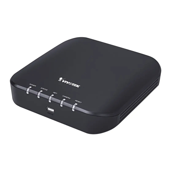
VIVOTEK - Built with Reliability Physical Description Front View 1 Activity LED: Please refer to page 19 for LED definitions. 2 USB 2.0 port Rear View 1 Power socket (DC12V, 1A) 4 USB 3.0 port 2 10/100/1000Mbps uplink port 5 Reset button 3 HDMI 10 - User's Manual... -
Page 11: Topology
VIVOTEK - Built with Reliability IMPORTANT: It is important to leave a clearance of 10cm around the chassis. The clearance is required to ensure an adequate airflow through the chassis to ventilate heat. To ensure normal operation, maintain ambient airflow. Do not block the airflow around chassis such as placing the system in a closed cabinet. -
Page 12: Hardware Installation
VIVOTEK - Built with Reliability Hardware Installation 1. Connect a mouse and/or keyboard to the USB connectors at the front or the rear of the re- ceiver. If you prefer to hang the Receiver on wall, drill and install two screws 104mm apart. 104mm 12 - User's Manual... -
Page 13: Interface Connections
VIVOTEK - Built with Reliability Interface Connections 1. Connect to a monitor using an HDMI cable. 2. Connect CAT5e or better-quality Ethernet cable to the network. 3. Connect USB devices such as mouse, keyboard, or USB thumb drive (formatted in FAT for- mat), or UPS. -
Page 14: Initial Configuration - Via A Local Console
VIVOTEK - Built with Reliability Initial Configuration - via a Local Console A local console requires the following: 1. A monitor or TV is connected via an HDMI cable. 2. A mouse and/or a keyboard are connected to the system. 3. - Page 15 VIVOTEK - Built with Reliability 3. The system will then start to scan the local subnet for connected cameras. 4. All cameras detected on the network will be automatically listed. If necessary, deselect the cameras you want to exclude from the configuration. Cameras properly installed in the same subnet should all be listed.
- Page 16 VIVOTEK - Built with Reliability Enter the credentials for each selected cameras on screen. Click Finish to proceed. NOTE: 1. The resolution and fps (frame rate per second) of stream 1 may vary depending on the specifications of different cameras. 2.
-
Page 17: Initial Configuration - Via A Web Console (Optional)
VIVOTEK - Built with Reliability Initial Configuration - via a Web Console (Optional) 1. Connec the power cord to start the Receiver. Wait for the system status LED to light green. 2. From a management computer, download and execute the Shepherd utility software. Follow the onscreen instructions to complete the installation. - Page 18 VIVOTEK - Built with Reliability 5. If you have configured a user name and password on the local console, use them to log in. Ideally, the initial configuration is performed via the local console. Expand the menu on the right of the Login button. Select and click on the Settings button to begin your configuration. If accessed for the first time and no password has been configured, enter admin and admin as user name and password.
-
Page 19: Led Indicators
VIVOTEK - Built with Reliability LED Indicators CAMERA RESET Name Behavior Definitions 1. Power Powered down. Solid Green Device is up and running. 2. Status Green solid System is ready. Blinking every 1 Firmware or device pack is being updated. second 3. -
Page 20: Power Up And Power Down
VIVOTEK - Built with Reliability Power Up and Power Down To power up and power down, On the initial configuration: Connect the power adapter between the system and power outlet. After the initial connection, Press the software power down button on the management session to power down. the system should start flushing the cached contents in system memory and gracefully shut down. - Page 21 VIVOTEK - Built with Reliability Section One Management over a Local Console Chapter Two Introduction to the Local Console Interface Camera 01 Camera 02 Camera 03 Camera 05 Camera 06 Camera 04 Camera 07 Camera 08 Camera 09 User's Manual - 21...
- Page 22 VIVOTEK - Built with Reliability By default, a live view appears on an HDMI monitor. The interface architecture of the local console is illustrated as follows: LiveView Main screen Main control portals Layout Overview Settings (camera connection & storage) Digital zoom Management Camera Media...
-
Page 23: How To Begin
VIVOTEK - Built with Reliability 2-1. How to Begin 1. How to access the Configuration Portal? Make sure a mouse is attached to your Receiver. Move your mouse cursor, and the Configuration Portal will appear on screen. For all the configurable options available through this portal, please refer to Chapter 3 on page 34. - Page 24 VIVOTEK - Built with Reliability PTZ control panel for ordinary PTZ control panel for joystick type PTZ PTZ type 5. Why live view is unavailable? The default live view receives a camera's stream #2. If a camera's stream #2 is configured using MPEG-4 as the video codec, the following message will prompt.
- Page 25 VIVOTEK - Built with Reliability User's Manual - 25...
- Page 26 VIVOTEK - Built with Reliability 6. How do I move to another layout page? Move your cursor to the right hand side of your screen. The page turner buttons will appear as shown below. For example, if you have 8 cameras placed on 2 2x2 layout pages, use these buttons to visit different pages.
-
Page 27: Operation On A Camera View Cell
VIVOTEK - Built with Reliability 2-2. Operation on a Camera View Cell The following apply when a camera view cell is selected. 2-2-1. PTZ Panel Once you selected a camera, click on the PTZ button on a camera portal. The PTZ panel will prompt. Below are the description of its functions: List of preset positions Focus far Focus near... - Page 28 VIVOTEK - Built with Reliability This portal appears with a fisheye camera. The PiP and PTZ buttons will then be disabled for a fisheye camera. IMPORTANT: Due to the limitation of system resources, the fisheye dewarp (1R & 1P) can only take place on one view cell, for one fisheye camera.
- Page 29 VIVOTEK - Built with Reliability Joystick support The joystick related operations are listed below: 1. Pan: Continuous move is supported. (joystick X-axis movement) 2. Tilt: Continuous move is supported. (joystick Y-axis movement) 3. Zoom: Continuous move is supported. To zoom in, move joystick Z-axis clockwise. To zoom out, move joystick Z-axis counter-clockwise.
- Page 30 VIVOTEK - Built with Reliability Manual Press once to start manual Recording recording. Press the second time to stop. Change Layout Consecutively changes layout Rewind Pause Play Speed Up Slow down Change focus In live view/playback layout, will view move from top left to lower right, from view cell to view cell.
-
Page 31: Digital Zoom Panel
VIVOTEK - Built with Reliability 2-2-2. Digital Zoom Panel Digital zoom is a function that allows an operator to zoom in or zoom out on a live video. When activated, a Global view window will appear at the lower right of the view cell as shown below. -
Page 32: Others
VIVOTEK - Built with Reliability 2-2-3. Others 1. Snapshot : is used to take a snapshot from the camera currently selected. Note that this function only saves the snapshot (in JPEG) to a USB thumb drive. IMPPORTANT: The USB thumb drive has to be one that is formatted in FAT format. 2. -
Page 33: Right-Click Commands
VIVOTEK - Built with Reliability 2-2-4. Right-click Commands Left-click to select a camera. Right-click to display the selection menu. 1. Camera information: Click to display camera name, resolution, codec, or frame rate on the view cell. The information will display on the upper left corner of a view cell. 2. -
Page 34: Chapter Three Configuation Using The Local Console
VIVOTEK - Built with Reliability Chapter Three Configuation Using the Local Console The Main Control Portal 3-1. Layout Move your mouse cursor across the screen to display the portal. The first functional button is Layout. You can select the 1x1, 2x2, 3x3, 4x4, 1M+5, 1M+12, 1M+31, 1P+3, 1P+6, 2P+3, 3V layout as the screen display. -
Page 35: Settings
VIVOTEK - Built with Reliability 3-2. Settings 3-2-1. Settings - Overview Click the Settings button to start the camera and system settings window. A confirm box will prompt. Enter User name and Password to proceed. The system will default to the overview page displaying the camera connection statuses. An empty position will be left in blank, and a disconnected camera will be indicated as The Reboot, and Power-down buttons are also available on this page. -
Page 36: Settings - Camera - Management
VIVOTEK - Built with Reliability The Camera menu provides access to Management, Media, Image, Motion detection, and PTZ settings pages. 3-2-2. Settings - Camera - Management On the camera Management page, you can configure the following: 1. Recruit or disband cameras. 2. - Page 37 VIVOTEK - Built with Reliability To recruit cameras: 1. Click on the Add button. A list of cameras in the same subnet will appear. 2. Click the Add button, the camera will be placed at an unoccupied position. You may also expand the menu on the side of the Add button to select a position number.
- Page 38 VIVOTEK - Built with Reliability To disband cameras: 1. Click on the Remove button. A list of cameras in your configuration will appear. 2. The Remove button will turn yellow . Mouse over to the camera you want to remove, and its entry will display the Remove message. 3.
- Page 39 VIVOTEK - Built with Reliability For legacy cameras, the receiver supports RTSP connections since firmware release revision 2.6.x. To manually add a legacy camera, 1. Select an empty camera entry, 2. Click the Add button, 3. Select RTSP as the protocol. 4.
- Page 40 VIVOTEK - Built with Reliability In Media > Stream managemeent page, the related Video, Audio, and stream configuration for RTSP cameras can not be edited. The RSTP cameras will be tagged. 40 - User's Manual...
- Page 41 VIVOTEK - Built with Reliability Network On the Network tabbed window, you can configure the network type, IP address, and the connection ports for video streaming. You can select DHCP as the method for cameras to acquire IP addresses, or you can manually configure static IPs for a single or all cameras.
- Page 42 VIVOTEK - Built with Reliability Camera position To change a camera's position on the Liveview layout, click and drag a camera to an unpopulated position. Note that you cannot swap the positions of two cameras by dragging a camera onto a position already populated by the other. Also, the camera index number on the management list is not affected by the change of positions.
-
Page 43: Settings-Camera-Media
VIVOTEK - Built with Reliability 3-3-1. Settings–Camera–Media The receiver automatically changes camera stream settings when cameras are added. If users want to manually configure camera stream setting, they can disable this function. The default for the automatic configuration is, • Main stream: H.265 1080p •... - Page 44 VIVOTEK - Built with Reliability The receiver adaptively selects to display a video stream of a different resolution when it is displaying on a smaller view cell or a full screen. 44 - User's Manual...
- Page 45 VIVOTEK - Built with Reliability Video The Video window allows you to configure all video streams (the no. of stream available can be different for different models). You can configure the following: 1. Codec: video compression codec in H.264, MPEG-4, or MJPEG. Note that MPEG-4 is not supported for Liveview.
- Page 46 VIVOTEK - Built with Reliability ■ Dynamic Intra frame period High quality motion codecs, such as H.265, utilize the redundancies between video frames to deliver video streams at a balance of quality and bit rate. The encoding parameters are summarized and illustrated below. The I-frames are completely self- referential and they are largest in size.
- Page 47 VIVOTEK - Built with Reliability Smart codec effectively reduces the quality of the whole or the non-interested areas on a ■ screen and therefore reduces the bandwidth consumed. You can manually specify the video quality for the foreground and the background areas. Slide bar to the right - higher quality in the ROI areas Slide bar to the left - higher quality in the non-ROI...
- Page 48 VIVOTEK - Built with Reliability As the result, the lower screen is constantly displayed in high details, while the upper half is transmitted using a lower-quality format. Although the upper half is transmitted using a lower quality format, you still have an awareness of what is happening on the whole screen.
- Page 49 VIVOTEK - Built with Reliability Audio The Audio window allows you to configure all audio codec, sampling rate, and Microphone input gains. Depending on design of the camera models, some codecs may not be available. Also, there are cameras that come without embedded mircrophones. User's Manual - 49...
-
Page 50: Settings - System - Information
VIVOTEK - Built with Reliability 3-3-2. Settings - System - Information On this window, you can configure the following: 1. Change the system name. 2. Select the UI text language. 3. Configure system time, time zone, and if you are connected to a DNS server where Auto Daylight Saving time can be applied, you can acquire the associated setting from a server within your network. -
Page 51: Settings - System - Maintenance
VIVOTEK - Built with Reliability 3-3-2. Settings - System - Maintenance If the need arises for updating system firmware, acquire the update from VIVOTEK's technical support or download site. Locate the firmware binaries, and click the Import button. The upgrade should take several minutes to complete. -
Page 52: Settings - System - Display
VIVOTEK - Built with Reliability 3-3-3. Settings - System - Display On this page, you can configure the system to consecutively display (rotate) cameras' view cells on the Liveview window. For example, if you have 8 cameras in 2 2x2 layouts, the rotation can let you see the live views of all cameras by every few seconds. -
Page 53: Settings - User
VIVOTEK - Built with Reliability 3-4. Settings - User The User window allows you to change the administrator's password. 1. By default, there is only one user type: Administrator. 2. The administrator users can access all cameras recruited in the configuration. You can create new users using the add button, and create credentials and designate the access rights to individual cameras. -
Page 54: Login / Logout
VIVOTEK - Built with Reliability 3-4-1. Login / Logout Login Login required to view live streaming: If selected, users will be required to enter his/her credentials before displaying a live view. If not selected, the Receiver displays live view first. Login will be required when performing specific tasks, such as entering the Settings page. -
Page 55: Settings - Network
VIVOTEK - Built with Reliability 3-5. Settings - Network Settings - Network - IP DHCP: Default is selected, the server obtains an available dynamic IP address assigned by the DHCP server each time the system is connected to the LAN. Manual setup: Select this option to manually assign a static IP address to the Network Camera. -
Page 56: Settings - Ddns
VIVOTEK - Built with Reliability Settings - DDNS VIVOTEK provides Dyndns.org, as a free DDNS dynamic domain name service for users who want access from the internet or a domain name service for the Receiver. VIVOTEK maintains a database of product MAC addresses for the service, and you can apply one domain name for each Receiver system. -
Page 57: Settings - Service
VIVOTEK - Built with Reliability Settings - Service By default, the Receiver service and video streaming are accessed via HTTP port 80 and RTSP port 554. You can designate a different port number if the need arises. Usually it is not necessary to change these ports. - Page 58 VIVOTEK - Built with Reliability VSS auto connection NAT-traversal with OpenVPN You can select the "VSS Server with OpenVPN" option when installing the VSS server. A remote connection from Receiver via a 3G/4G/LTE network can be made through an OpenVPN tunnel. When the OpenVPN option is selected, an OpenVPN server will be installed with the VSS server.
- Page 59 VIVOTEK - Built with Reliability With a remote VSS instance that needs to access the Receiver via the Internet, you can enter its public IP address and credentials. The Receiver runs an Open VPN client that makes remote connection via the RESTful (Repretational State Transfer) API (Application Programming Interface) service to a VPN server running on the remote site.
- Page 60 VIVOTEK - Built with Reliability Note that the receiver and VSS server should have a similar time setting when exchanging certificate information. Otherwise, the mutual handshake authentication process may fail. Enter the OpenVPN DNS domain name and the credentials on the Receiver network service configuration page.
-
Page 61: Https Certificate
VIVOTEK - Built with Reliability 3-6. HTTPS certificate This window allows the export, import, and to create an HTTPS certificate for secure connection to the receiver. User's Manual - 61... -
Page 62: User
VIVOTEK - Built with Reliability 3-7. User The User window allows you to create more users, to change user password, and place limitations on users' privileges and administration rights. Up to 16 users can be created, including the default administrator. 1. - Page 63 VIVOTEK - Built with Reliability To create or edit users, 1. Select a User group by unfolding its pull-down menu. Select either an Administrator or regular user as the user group. 2. Enter the User name and password. The max. number of characters for a user name is 64, with alphabetic and numeric characters including [0-9][a-z][A-Z][_][ ][-][.][,][@].
-
Page 64: Settings-User-Login / Logout
VIVOTEK - Built with Reliability 3. If you are creating a regular user with limited access to cameras, deselect the checkboxes by the cameras to deny the user access. 4. Click Apply to close the configuration window. Repeat the process to create more users. Settings–User-Login / Logout Login Login required to view live... -
Page 65: Information
VIVOTEK - Built with Reliability 3-8. Information This window shows the revision number of the firmware running on this machine. User's Manual - 65... -
Page 66: Section Two Management Over A Web Console
VIVOTEK - Built with Reliability Section Two Management over a Web Console There are two different interfaces on the system: 1. One is connecting mouse and keyboard, and an HDMI cable to a TV or monitor. The local management thus made is described in Section One of this manual. 2. - Page 67 VIVOTEK - Built with Reliability Some minor differences between the web console and local console exist. One is the Restore Factory default function. It is only available on the web console. On the chassis, you can press the Restore/WPS button for longer than 10 seconds to restore system defaults.
- Page 68 VIVOTEK - Built with Reliability Another difference is the ability to enter a system name using languages other than English. The Receiver's system name also supports the use of other lanaguages. This is only achievable through a web console. The following characters are not supported: [>][<][)][(]["][%][;][#][&][+][-][\] On the System >...
- Page 69 VIVOTEK - Built with Reliability Safety and Compatibility Federal Communications Commission (FCC) Statement This Equipment has been tested and found to comply with the limits for a Class A digital device, pursuant to Part 15 of the FCC rules. These limits are designed to provide reasonable protection against harmful interference when the equipment is operated in a commercial environment.
- Page 70 VIVOTEK - Built with Reliability Japan VCCI Class A statement ACA (Australian Communications Authority) CAUTION RISK OF EXPLOSION IF BATTERY IS REPLACED BY AN INCORRECT TYPE. DISPOSE OF USED BATTERIES ACCORDING TO THE INSTRUCTIONS 70 - User's Manual...
Need help?
Do you have a question about the Vivotek RX9502 and is the answer not in the manual?
Questions and answers