Table of Contents
Advertisement
Quick Links
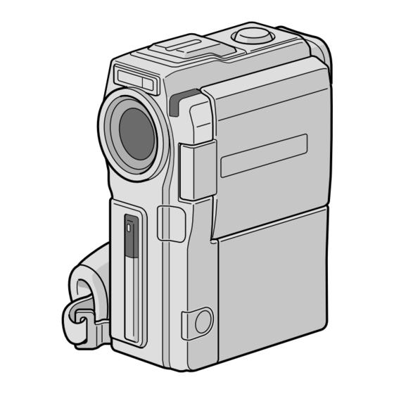
DIGITAL VIDEO CAMERA
GR-DVX90
GR-DVX9
Please visit our Homepage on the World Wide
Web and answer our Consumer Survey
(in English only):
http://www.jvc-victor.co.jp/english/index-e.html
INSTRUCTIONS
Downloaded from:
https://www.usersmanualguide.com/
CONTENTS
Basic Recording For Video ........................ 16
Basic Recording For Video And D.S.C. .......... 20
Advanced Features For Video And D.S.C. ...... 22
Basic Playback For Video ......................... 40
Advanced Features For Video ................... 41
Basic Playback For D.S.C. ........................ 45
Advanced Features For D.S.C. ................... 48
Basic Connections .................................. 56
Advanced Connections ............................ 58
Dubbing To A VCR ................................. 60
Dubbing From A VCR .............................. 61
Equipped With A DV Connector ................ 62
Equipped With A DV Connector ................ 63
MultiMediaCard To A Tape ..................... 64
On A Tape To A MultiMediaCard .............. 65
Playback and Playback Zoom .................. 68
Playback Special Effects .......................... 69
Random Assemble Editing ........................ 70
For More Accurate Editing ........................ 74
Audio Dubbing ...................................... 76
Docking Station .................................... 85
Controls, Connectors And Indicators ............ 86
Indications .......................................... 88
LYT0636-001A
ENGLISH
6 - 15
16 - 39
40 - 55
56 - 59
60 - 65
66 - 77
78
79 - 84
85 - 92
93 - 95
96 - 97
98 - 99
EN
Advertisement
Table of Contents

Related Manuals for JVC GR-DVX90


Summary of Contents for JVC GR-DVX90
-
Page 1: Table Of Contents
40 – 55 DIGITAL VIDEO CAMERA Basic Playback For Video ......40 Advanced Features For Video ....41 Basic Playback For D.S.C......45 GR-DVX90 Advanced Features For D.S.C....48 CONNECTIONS 56 – 59 Basic Connections ........56 GR-DVX9 Advanced Connections ...... - Page 2 If you notice smoke or a peculiar smell coming from the camcorder or AC adapter/charger, shut it down and unplug it immediately. Continue using the camcorder or AC adapter/charger under these conditions could lead to fire or electric shock. Contact your JVC dealer. Do not attempt to repair the malfunction yourself.
- Page 3 When the equipment is installed in a cabinet or on a shelf, make sure that it has sufficient space on all sides to allow for ventilation (10 cm or more on both sides, on top and at the rear). Do not block the ventilation holes. (If the ventilation holes are blocked by a newspaper, or cloth etc.
- Page 4 ® • Picture Navigator (for Windows ® • Picture Navigator (for Macintosh • CardNavigator • Video Player • JVC Video Decoder Mr. Photo Gold •Editing Cable •Audio/Video Cable • Mr. Photo (One plug has 3 rings around (ø3.5 mini-plug to •...
-
Page 5: Automatic Demonstration
AUTOMATIC DEMONSTRATION Automatic Demonstration takes place when “DEMO. MODE” is set to “ON” (factory-preset). Available when the POWER Switch is set to “ ” and no cassette is in the camcorder. Performing any operation during the demonstration stops the demonstration temporarily. If no operation is performed for more than 1 minute after that, the demonstration will resume. -
Page 6: Getting Started
GETTING STARTED Power CHARGE Battery pack indicator BN-V507U or This camcorder’s 2-way power supply system lets you BN-V514U choose the most appropriate source of power. Do not use POWER AC outlet provided power supply units with other equipment. indicator CHARGING THE BATTERY PACK Make sure you unplug the camcorder’s DC cord from the AC Power Adapter/Charger. - Page 7 USING THE BATTERY PACK Insert the terminal end of the battery pack into the battery pack mount, then firmly push the end the battery pack in the direction of the arrow until it locks into place as shown in the illustration. •If the battery pack is attached in the wrong position, a malfunction may occur.
- Page 8 GETTING STARTED (cont.) Grip Adjustment Power Zoom Lever Separate the Velcro strip. Pass your right hand through the loop and grasp the grip. Adjust so that your thumb and fingers can easily operate the START/STOP Button and Power Zoom Lever. Refasten the Velcro strip. START/STOP Button Lock Button Viewfinder Adjustment...
- Page 9 Date/Time Settings POWER Switch The date/time is recorded onto the tape at all times, but its POWER Lamp display can be turned on or off during playback ( pg. 41). Set the Operation Switch to “ ” and set the POWER Lock Button Switch to “...
- Page 10 GETTING STARTED (cont.) Loading/Unloading A Cassette Cassette holder cover Cassette holder The camcorder needs to be powered up to load or eject a cassette. Slide down and hold OPEN/EJECT in the direction of the arrow then pull the cassette holder cover open until it locks.
- Page 11 Recording Mode Setting POWER Switch Set the tape recording mode depending on your preference. POWER Lamp Set the Operation Switch to “ ” and set the POWER Switch to “ ” while pressing down the Lock Lock Button Button located on the switch, then open the LCD monitor fully or pull out the viewfinder fully.
- Page 12 GETTING STARTED (cont.) Loading A MultiMediaCard The provided MultiMediaCard is already inserted in the camcorder when you receive the camcorder. Make sure the camcorder’s power is off. Card Cover Open the card cover. Insert the MultiMediaCard clipped edge first. •Do not touch the terminal on the reverse side of the label.
- Page 13 Picture Quality/Size Mode Setting MODE Dial Picture quality and size can be selected to best match your POWER Switch needs. Four different modes are available: XGA (1024 x 768 pixels) FINE, XGA STD, VGA (640 x 480 pixels) FINE and VGA STD, listed in order of quality. POWER Lamp Set the POWER Switch to “...
- Page 14 GETTING STARTED (cont.) Operation Mode To turn on the camcorder, set the POWER Switch to any operation mode except “OFF” Choose the appropriate operation mode according to your while pressing down the Lock Button located preference using the POWER Switch, Operation Switch on the switch.
- Page 15 MODE Dial MODE Dial unction Position MODE •Allows you to record video on a tape and store still images in a MultiMediaCard simultaneously pg. 24). •File size of still images: 640 x 480 pixels •Video quality is the same as in the VIDEO mode.
-
Page 16: Recording
RECORDING Basic Recording For Video NOTE: POWER Switch You should already have performed the procedures listed below. If not, do so before continuing. POWER Lamp ● Power ( pg. 6) ● Grip Adjustment ( pg. 8) ● Viewfinder Adjustment ( pg. - Page 17 NOTES: ● When you use the LCD monitor outdoors in direct sunlight, the LCD monitor may be difficult to see. If this happens, use the viewfinder instead. ● The image will not appear simultaneously in the LCD monitor and the viewfinder. ●...
- Page 18 RECORDING Basic Recording For Video (cont.) Snapshot (For Video Recording) MENU Wheel MODE Dial This feature lets you record still images that look like photographs onto a tape. POWER Switch SNAPSHOT MODE SELECTION Set the POWER Switch to “ ” while pressing Lock Button down the Lock Button located on the switch and the MODE Dial to “VIDEO”...
-
Page 19: Basic Recording For Digital Still Camera (D.s.c.)
RECORDING Basic Recording For Digital Still Camera (D.S.C.) Basic Shooting (Snapshot) MENU Wheel MODE Dial You can use your camcorder as a Digital Still Camera for taking snapshots. POWER Switch NOTE: You should already have performed the procedures listed below. If not, do so before continuing. -
Page 20: Basic Recording For Video And D.s.c
RECORDING Basic Recording For Video And D.S.C. Zoom in (T: Telephoto) Zooming FEATURE: PURPOSE: 1 xW 1 0 xW To produce the zoom in/out effect, or an instantaneous 20xW 40xW change in image magnification. OPERATION: Zoom In Slide the Power Zoom Lever towards “T”. Zoom Out Zoom out (W: Wide angle) Slide the Power Zoom Lever towards “W”. - Page 21 NOTE: Recording From The Middle Of A Tape Time Code During recording, a time code is recorded on the tape. This code is to confirm the location of the recorded scene on the tape during playback. If recording starts from a blank portion, the time code begins counting from “00:00:00” (minute:second:frame).
-
Page 22: Advanced Features For Video And D.s.c
RECORDING Advanced Features For Video And D.S.C. Progressive Mode Recording START/STOP Button MODE Dial This mode lets you record moving images (successive jitter-free still images) onto a tape. Images can then played back jitter-free, with superior quality. High-resolution still POWER Switch images can also be processed on a personal computer or can be printed out ( pg. - Page 23 Description of Progressive Scan CCD Progressive Scan is a special image sensing method which, unlike conventional interlace scanning, is able to pick up all the lines of picture information in one Scan. Since the Progressive Scan CCD is capable of outputting 50 full Frames* per second —...
- Page 24 RECORDING Advanced Features For Video And D.S.C. (cont.) Dual Shooting Lets you record images on a tape and store still images in a FOCUS Button (3) MultiMediaCard simultaneously. In other words, it is possible to store still images in the MultiMediaCard without interrupting image recording on the tape.
- Page 25 Focus detection zone While focusing on a further While focusing on a nearer subject subject FOCUS FOCUS Auto Focus FEATURE: PURPOSE: The camcorder’s Full Range AF system offers continuous shooting ability from close-up (as close as approx. 5 cm to the subject) to infinity. However, correct focus may not be obtainable in the situations listed below (in these cases use manual focusing): •When two subjects overlap in the same scene.
- Page 26 RECORDING Advanced Features For Video And D.S.C. (cont.) Using Menus For Detailed Adjustment POWER Switch This camcorder is equipped with an easy-to-use, on-screen menu system that simplifies many of the more Lock Button detailed camcorder settings ( pg. 27 – 29) . Operation Switch Set the Operation Switch to “...
- Page 27 Menu Screen Explanations Refer to “Fade/Wipe Effects” ( pg. 34, 35). FADER/WIPE Refer to “Programme AE With Special Effects” ( pg. 36). P.AE/EFFECT Refer to “White Balance Adjustment” and “Manual White Balance Operation” W.BALANCE pg. 39). Allows you to set the recording mode (SP or LP) depending on your REC MODE preference ( pg.
- Page 28 RECORDING Advanced Features For Video And D.S.C. (cont.) Menu Screen Explanations (cont.) Demonstrates certain functions such as Programme AE with special effects, DEMO. etc., and can be used to confirm how these functions operate. When “DEMO. MODE MODE” is set to “ON” and the Menu Screen is closed, demonstration starts. Performing any operation during the demonstration stops the demonstration temporarily.
- Page 29 Disengages the function which cuts down on noise created by wind. WIND Helps cut down on noise created by wind. “ ” appears. The quality of the sound will change. This is normal. Refer to “Snapshot Flash” ( pg. 30). FLASH Refer to “Flash Brightness Adjustment”...
- Page 30 RECORDING Advanced Features For Video And D.S.C. (cont.) Snapshot Flash MENU Wheel POWER Switch The flash can be used when a snapshot is taken in Record- Standby ( pg. 18, 19). •In Full Auto mode, the flash automatically fires if it is dark ( appears).
- Page 31 Flash Brightness Adjustment POWER Switch When a snapshot ( pg. 18, 19) is taken in the dark the camcorder fires the flash ( pg. 30) and adjusts the brightness automatically. You can also adjust the flash brightness manually. When you find that the snapshots Lock Button you took look too bright or too dark, adjust it manually.
- Page 32 RECORDING Advanced Features For Video And D.S.C. (cont.) Self-Timer START/STOP Button POWER Switch Once the camcorder is set, the camcorder operator can become part of the scene in a more natural way, adding the final touch to a memorable picture. Set the Operation Switch to “...
- Page 33 5-Second Recording START/STOP Button MODE Dial Record a vacation or an important event in 5-second clips to keep the action moving. This function is available only POWER Switch for video recording. Set the POWER Switch to “ ” while pressing down the Lock Button located on the switch and set Lock Button the MODE Dial to “VIDEO”, “...
- Page 34 RECORDING Advanced Features For Video And D.S.C. (cont.) Fade/Wipe Effects FADE/WIPE SELECTION ( These effects let you make pro-style scene Fade or Wipe works when video recording is started or transitions. Use them to spice up the transition when you stop recording. from one scene to the next.
- Page 35 Fader And Wipe Menu Menu Effect Fade in or out with a white screen. FADER — WHITE Fade in or out with a black screen. FADER — BLACK Fade in to a colour screen from a black and white screen, or fade out FADER —...
- Page 36 RECORDING Advanced Features For Video And D.S.C. (cont.) Programme AE With Special Effects IMPORTANT: Some modes of Programme AE with special effects cannot be used with certain Fade/Wipe Set the Operation Switch to “ ”, then set the Effects ( pg.
- Page 37 To cancel recording the sound effect midway . . . MultiMediaCard to create more sound ..press DIGITAL SOUND again. The camcorder stops effects. recording the sound effect and the sound effect http://www.jvc-victor.co.jp/english/ indication disappears. download/d-sound/index.html NOTES: • Use the PC card adapter CU-V50U or ●...
- Page 38 RECORDING Advanced Features For Video And D.S.C. (cont.) Exposure Control Iris Lock Use this function in the following situations: Manual exposure adjustment is recommended in the • When shooting a moving subject. following situations: • When the distance to the subject changes (so its •...
- Page 39 White Balance Adjustment Manual White Balance Operation A term that refers to the correctness of colour Perform Manual White Balance when shooting under reproduction under various lighting. If the white various types of lighting. balance is correct, all other colours will be Follow steps 1 through 4 of the white balance accurately reproduced.
-
Page 40: Playback
PLAYBACK Basic Playback For Video Load a tape ( pg. 10). Play/Pause Button (4/6) Fast-Forward Button (3) Set the POWER Switch to “ ” while pressing down the Lock Button located on the switch. To start Rewind Button (2) playback, press 4/6. •To stop playback, press 5. -
Page 41: Advanced Features For Video
PLAYBACK Advanced Features For Video Using Menus For Detailed Adjustment START/STOP Button POWER Switch The following procedure applies to all except Synchro Comp ( pg. 74, 75). Set the POWER Switch to “ ” while pressing down the Lock Button located on the switch. Lock Button Press the MENU wheel. - Page 42 PLAYBACK Advanced Features For Video (cont.) Playback Sound During playback, the camcorder detects the sound mode in which the recording was made, and plays the sound back. Select the type of sound to accompany your playback picture. According to the menu access explanation on pg.
- Page 43 Blank Search Stop Button (5) Helps you find where you should start recording in the POWER Switch middle of a tape to avoid time code interruption ( pg. 21). Load a tape ( pg. 10) and set the POWER Switch to “...
- Page 44 ● If the end of the tape is reached in step 3, the E-Mail Clip Record-Standby mode will be automatically cancelled. ● Refer to the instruction manual of the provided software, CardNavigator, Video Player and JVC Video Decoder. ● Video noise may appear while viewing video clips in the Storing is complete...
-
Page 45: Basic Playback For D.s.c
PLAYBACK Basic Playback For D.S.C. Normal Playback Play Button (4/6) Images shot with the camcorder are automatically Fast-Forward Button (3) numbered, then stored in numerical order in the MultiMediaCard. You can view the stored images, one at a Rewind Button (2) time, much like flipping through a photo album. - Page 46 PLAYBACK Basic Playback For D.S.C. (cont.) Index Screen Picture Quality/Size Type of file mode: Appears only The files you stored can be displayed together with their when displaying still Directory and index information. Convenient for checking files stored images File names beforehand, the Index Screen also shows the Picture Quality/Size mode, directory and file names as well as Index number...
- Page 47 Index Playback You can view or listen to the files (still images, video clips, or sound effects) stored in memory six at a time. Use this mode when looking for a file you wish to view or hear. Perform steps 1 and 2 of “Normal Playback” on pg.
-
Page 48: Advanced Features For D.s.c
PLAYBACK Advanced Features For D.S.C. Protecting Files POWER Switch The Protect mode helps prevent the accidental erasure of files. When a padlock mark is displayed next to the index number, that file cannot be deleted. Lock Button Set the POWER Switch to “ ”... - Page 49 Deleting Files POWER Switch Previously stored files can be deleted either one at a time or all at once. Set the POWER Switch to “ ” while pressing Lock Button down the Lock Button located on the switch. Open the LCD monitor fully or pull out the viewfinder fully. •A stored file is displayed.
- Page 50 PLAYBACK Advanced Features For D.S.C. (cont.) Initialising A MultiMediaCard POWER Switch You can initialise a MultiMediaCard anytime. After initialising, all images and data stored in the MultiMediaCard, including those which have been protected, are cleared. Lock Button Set the POWER Switch to “ ”...
- Page 51 Superimposing A Print Frame PRINT FRAME Button A selection of print frames are stored in the camcorder. A frame can be superimposed over a still image. Play back an image stored in the MultiMediaCard. Press PRINT FRAME. The Print Frame Index Screen appears.
- Page 52 PLAYBACK Advanced Features For D.S.C. (cont.) Print Frame Deletion POWER Switch A print frame created on a PC can be transferred to a MultiMediaCard using the provided software. Print frames that have been transferred to a MultiMediaCard can be deleted when they are no longer needed. Lock Button There are 2 ways of deleting previously created print frames: by browsing through print frames individually or...
- Page 53 TO DELETE ALL PRINT FRAMES POWER Switch Perform steps 1 through 4 on pag. 52. Rotate the MENU wheel to select “ALL” and press it. Lock Button The Deletion Confirmation Screen appears. Rotate the MENU wheel to select “EXECUTE” and press it.
- Page 54 PLAYBACK Advanced Features For D.S.C. (cont.) Setting Print Information (DPOF Setting) POWER Switch This camcorder is compatible with the DPOF (Digital Print Order Format) standard in order to support future systems such as automatic printing, which records information about the still images you wish to print (such as the Lock Button number of prints to make).
- Page 55 TO PRINT BY SELECTING STILL IMAGES POWER Switch AND NO. OF PRINTS Perform steps 1 through 4 on pg. 54. Lock Button Rotate the MENU wheel to selsect “SELECT” and press it. Selection is complete. The DPOF Screen appears. Rotate the MENU wheel to move the green frame to the image you wish to print and press it.
-
Page 56: Connections
CONNECTIONS Basic Connections These are some basic types of connections. When making the connections, refer also to your VCR and TV instruction manuals. A. Connection to a TV or VCR equipped only with A/V input (RCA type) connectors To TV or VCR Audio/Video cable White to [mini-plug to RCA plug]... - Page 57 NOTES: Make sure all units are turned off. ● It is recommended to use the AC Power Adapter/ Charger as the power supply instead of the battery pack ( pg. 7). Connect the camcorder to a TV or VCR as ●...
-
Page 58: Advanced Connections
CONNECTIONS Advanced Connections Connection To A Personal PC with DV connector-equipped Computer capture board This camcorder can transfer still images to a PC by using the provided software when connected as shown in the illustration. It is also possible to transfer still images to a PC with a DV connector-equipped capture board installed. - Page 59 ● Also refer to the instruction manuals of the connected units. ● When using a DV cable, be sure to use the optional JVC To PC VC-VDV204U DV cable. connector...
-
Page 60: Dubbing
DUBBING Dubbing To A VCR POWER Switch [To use this camcorder as a player] Lock Button Following the illustration, connect the camcorder and the VCR. Also refer to pg. 56 and 57. Set the camcorder’s POWER Switch to “ ” while pressing down the Lock Button located on the switch, turn on the VCR’s power, and insert the appropriate cassettes in the camcorder and the VCR. -
Page 61: Dubbing From A Vcr
Dubbing From A VCR POWER Switch [To use this camcorder as a recorder] Lock Button Make sure all units are turned off, then connect the camcorder and the VCR as shown in the illustration. Also refer to pg. 56 and 57. Set “SOUND MODE”... -
Page 62: Dubbing To A Video Unit Equipped With A Dv Connector
69) or “Snapshot” is attempted during playback, only the original playback image recorded on the tape is output from the DV OUT connector. ● When using a DV cable, be sure to use the optional JVC PLAY (4) VC-VDV204U DV cable. -
Page 63: Dubbing From A Video Unit Equipped With A Dv Connector
● It is recommended to use the AC Power Adapter/ Charger as the power supply instead of the battery pack pg. 7). ● If the remote control is used when both the player and recorder are JVC video units, both units will perform the same operation. To prevent this from happening, press the buttons on both units. -
Page 64: Dubbing Images Stored In A Multimediacard To A Tape
DUBBING (cont.) Dubbing Images Stored In A Rewind Button (2) MultiMediaCard To A Tape Fast-Forward Button (3) Images can be dubbed from a MultiMediaCard to a tape. Load a MultiMediaCard ( pg. 12) and cassette pg. 10). POWER Switch Set the POWER Switch to “ ”... -
Page 65: Dubbing Images Recorded On A Tape To A Multimediacard
Dubbing Images Recorded On A Tape To A MENU Wheel MultiMediaCard POWER Switch Images can be dubbed from a tape to a MultiMediaCard. Load a MultiMediaCard ( pg. 12) and cassette Lock Button pg. 10). Set the POWER Switch to “ ”... -
Page 66: Using The Remote Control Unit
USING THE REMOTE CONTROL UNIT The Full-Function Remote Control Unit can operate this camcorder from a distance as well as the basic operations (Playback, Stop, Pause, Fast-Forward and Rewind) of your VCR. It also makes additional playback functions possible. Installing The Batteries The remote control uses two “AAA (R03)”... - Page 67 & Functions With the camcorder’s POWER Buttons With the camcorder’s POWER Switch set to the camera position Switch set to “ ” or (“ ”). “ ”. Infrared beam transmitting window Transmits the beam signal. Zoom (T/W) Buttons Zoom in/out ( pg.
-
Page 68: Slow-Motion Playback, Frame-By-Frame Playback And Playback Zoom
USING THE REMOTE CONTROL UNIT (cont.) Slow-Motion Playback FEATURE: PURPOSE: To allow slow-speed search in either direction during video playback. Remote sensor OPERATION: 1) To change from normal to Slow-Motion Playback, press SLOW (9 or 0) more than approx. 2 seconds. After approx. -
Page 69: Playback Special Effects
BACK PLAYBACK Playback Special Effects FEATURE: EFFECT Select Menu PURPOSE: To allow you to add creative effects to the video playback image. OPERATION: 1) To start playback, press PLAY (4). 2) Point the remote control at the camcorder's remote sensor and press EFFECT. The PLAYBACK EFFECT Select Menu appears. -
Page 70: Random Assemble Editing
(A) (B) IMPORTANT 6 2 1 9 AKAI PHILIPS Although the MBR is compatible with JVC VCRs and 6 4 9 5 those of many other makers, it may not work with 1 1 yours or may offer limited functions. - Page 71 MAKE CONNECTIONS Also refer to pg. 56 and 57. A JVC VCR equipped with a remote pause connector ..connect the editing cable to the Remote PAUSE connector. A JVC VCR not equipped with a remote pause connector but equipped with an R.A.
- Page 72 USING THE REMOTE CONTROL UNIT (cont.) SELECT SCENES Programme Point the remote control at the camcorder’s remote MODE Random Assemble – – – – – – sensor. Press PLAY (4) and then press R.A.EDIT ON/ Editing Menu OFF on the remote control. The Random Assemble Editing Menu appears.
- Page 73 AUTOMATIC EDITING TO VCR Rewind the tape in the camcorder to the beginning of the scene you want to edit and press PAUSE (6). Point the remote control towards the VCR’s remote sensor and press VCR REC STBY (q6), or manually engage the VCR’s Record-Pause mode.
-
Page 74: For More Accurate Editing
USING THE REMOTE CONTROL UNIT (cont.) For More Accurate Editing Programme 1 Some VCRs make the transition from Record-Pause to MODE Random Assemble Record mode faster than others. Even if you begin editing – – – – – – Editing Menu for the camcorder and the VCR at exactly the same time, you may lose scenes you wanted, or find that you have recorded scenes you did not want. - Page 75 ADJUSTMENT OF VCR/CAMCORDER TIMING Point the remote control at the camcorder’s remote sensor and press R.A.EDIT ON/OFF to make the Random Assemble Editing menu disappear, then press the MENU wheel. The Menu Screen appears. Rotate the MENU wheel to select “ ”...
-
Page 76: Audio Dubbing
USING THE REMOTE CONTROL UNIT (cont.) Audio Dubbing Display Audio Dub The audio track can be customized only when recorded in Standby mode the 12-bit mode ( pg. 27). NOTES: ● Audio Dubbing is not possible on a tape recorded in 16- bit audio, on a tape recorded in the LP mode or on a blank portion of a tape. -
Page 77: Audio Dubbing Using Digital Sound Effects
Audio Dubbing Using Digital Sound Effects Display Audio Dub Standby mode Load the provided MultiMediaCard ( pg. 12) and EXPLOS I ON perform step 1 and 2 of page 76. Press EDIT IN/OUT so that “ ” appears. •To select the sound effect, press INDEX to display the SOUND Index Screen ( pg. -
Page 78: User Maintenance
USER MAINTENANCE After Use Cleaning The Camcorder Turn off the camcorder. To clean the exterior, wipe gently with a soft cloth. Put the cloth in diluted mild soap and wring it Slide down and hold OPEN/EJECT in the well to wipe off heavy dirt. Then wipe again direction of the arrow, then pull the cassette with a dry cloth. -
Page 79: Troubleshooting
TROUBLESHOOTING If, after following the steps in the chart below, the problem still exists, please consult your nearest JVC dealer. The camcorder is a microcomputer-controlled device. External noise and interference (from a TV, a radio, etc.) might prevent it from functioning properly. In such cases, first disconnect its power supply unit (battery pack, AC Power Adapter/Battery Charger, etc.) and wait a few minutes;... - Page 80 TROUBLESHOOTING (cont.) SYMPTOM POSSIBLE CAUSES CORRECTIVE ACTION 11. The colour of Snapshot looks 11. • The light source or the subject 11. • Set “FLASH” to “ON” in the strange. does not include white. Or Menu Screen. Or find a white there are various different subject and compose your light sources behind the...
- Page 81 SYMPTOM POSSIBLE CAUSES CORRECTIVE ACTION 17. Programme AE with special 17. • The Operation Switch is set to 17. • Set the Operation Switch to effects and Fade/Wipe Effects “ ”. “ ” ( pg. 34, 36). do not work. 18.
- Page 82 LCD monitor become dark. Consult your nearest JVC dealer. 33. The rear of the LCD monitor 33. • The light used to illuminate 33. • Close the LCD monitor to turn is hot.
- Page 83 SYMPTOM POSSIBLE CAUSES CORRECTIVE ACTION 35. • Re-read the sections covering 35. The LCD monitor or 35. • Certain Fade/Wipe effects, viewfinder indications blink. certain modes of Programme Fade/Wipe effects, AE with special effects, “DIS” Programme AE with special and other functions that effects and “DIS”...
- Page 84 If the indication remains even though you repeat the above two or three times, please consult your nearest JVC dealer. 48. The charger indicator on the 48. • The temperature of the battery 48. • To protect the battery, it is AC Power Adapter/Charger is extremely high/low.
-
Page 85: Index
INDEX Docking Station PC Connector [DIGITAL STILL] .... pg. 58 PRINTER Connector Connect to the optional printer equipped with a J Terminal/Edit Connector PRINT DATA connector. Refer to the separate [JLIP (Joint Level Interface Protocol) “FOR OWNERS OF AN OPTIONAL PRINTER” (EDIT)] .......... -
Page 86: Controls, Connectors And Indicators
INDEX Controls, Connectors And Indicators 1 2 3 & Downloaded from: https://www.usersmanualguide.com/... - Page 87 Controls Connectors PRINT Button The connectors are located beneath a cover. Enables printing using the optional printer Digital Video Connector equipped with a PRINT DATA connector. Refer to [DV IN/OUT] (i.link*) ..pg. 58, 59, 62, 63 the separate “FOR OWNERS OF AN OPTIONAL * i.Link refers to the IEEE1394-1995 industry PRINTER”...
- Page 88 INDEX Indications LCD Monitor/Viewfinder Indications During Video Recording Only Displays the selected Fade/Wipe effect. pg. 34, 35) 3 * 4 * Appears when in the Squeeze, Cinema or PS Wide mode. pg. 28) * Displays the recording mode (SP or LP). SP 3 5 pg.
- Page 89 LCD Monitor/Viewfinder Indications During Both Video And D.S.C. Recording OS I ON & * Appears when the Operation switch • Approximate zoom ratio: Appears during is set to “ ”. pg. 14) zooming. pg. 20) • : Appears when “GAIN UP” is set to Displays the shooting mode position.
- Page 90 INDEX Indications (cont.) LCD Monitor/Viewfinder Indications During Video Playback Displays the sound mode. pg. 41, 42) Displays the selected Digital Sound Effect. pg. 37) Displays the tape speed. pg. 11) Appears while a tape is running. : Playback 3 : Fast-Forward/Shuttle search 2 : Rewind/Shuttle search : Pause 64 : Forward slow-motion...
-
Page 91: Indications
Warning Indications Indications Function Displays the battery remaining power. Remaining power level: high Remaining power level: exhausted As the battery power comes close to nil, the battery indicator blinks. When the battery power is exhausted, power turns off automatically. Appears when no tape is loaded. pg. - Page 92 Remove the power supply (battery, etc.) and wait a few MODE REMOVE AND minutes for the indication to clear. When it does, you can resume using the REATTACH BATTERY camcorder. If the indication remains, consult your nearest JVC dealer. Downloaded from: https://www.usersmanualguide.com/...
-
Page 93: Cautions
CAUTIONS General Battery Precautions Battery Packs If the remote control is not functioning even if it is The supplied battery pack is being operated correctly, the batteries are ex- a lithium-ion battery. Before hausted. Replace them with fresh ones. using the supplied battery pack or an optional battery Use only the following batteries: AAA (R03) size x 2 pack, be sure to read the... - Page 94 CAUTIONS (cont.) Cassettes LCD Monitor To properly use and store your cassettes, be sure to 1. To prevent damage to the LCD monitor, read the following cautions: DO NOT ..push it strongly or apply any shocks. 1.
- Page 95 If malfunctioning occurs, stop using the unit If, after using the cleaning cassette, the problems immediately and consult your local JVC dealer. still exist, consult your nearest JVC dealer. Mechanical moving parts used to move the video heads and video tape tend to become dirty and worn out over time.
-
Page 96: Terms
TERMS AC Power Adapter/Charger ..... pg. 6, 7 Fade-In/Out ........pg. 34, 35 Analogue Input ........pg. 41, 61 Fast-Forward The Tape ......pg. 40 Animation ..........pg. 33 5-second recording mode ......pg. 33 Audio Dubbing ........pg. 76 Flash .......... - Page 97 Picture Quality/Size Mode ......pg. 13 Tele Macro ..........pg. 28 Picture Wipe/Dissolve ......pg. 34, 35 Time Code ......pg. 21, 29, 41, 42 Playback Special Effects ......pg. 69 Tripod Mounting ......... pg. 8 Playback Zoom ........pg. 68 Twilight ............
-
Page 98: Specifications
SPECIFICATIONS Camcorder For General Power supply : DC 6.3 V (Using AC Power Adapter/Charger) DC 7.2 V (Using battery pack) Power consumption LCD monitor off, viewfinder on : Approx. 4.9 W LCD monitor on, viewfinder off : Approx. 5.8 W Dimensions (W x H x D) : 51 mm x 125 mm x 97 mm (with the LCD monitor closed and the viewfinder pushed back in) - Page 99 For Connectors , 75 Ω, analogue Video output : 1 V Audio output : 300 mV (rms), 1 kΩ, analogue, stereo DV Input/output : 4-pin, IEEE 1394 compliant Headphone output : ø3.5 mm, stereo AC Power Adapter/Charger AA-V51EA, AA-V51A, AA-V51A-S, AA-V51SH or AA-V51ED Power requirement : AC 110 V to 240 V`, 50 Hz/60 Hz Power consumption...
- Page 100 VICTOR COMPANY OF JAPAN, LIMITED ®Registered Trademark owned by VICTOR COMPANY OF JAPAN, LTD. Printed in Japan EA/A/A-S/SH/ED COPYRIGHT© 2000 VICTOR COMPANY OF JAPAN, LTD. 0700AYV Downloaded from: https://www.usersmanualguide.com/...
- Page 101 This file has been downloaded from: www.UsersManualGuide.com User Manual and User Guide for many equipments like mobile phones, photo cameras, monther board, monitors, software, tv, dvd, and othes.. Manual users, user manuals, user guide manual, owners manual, instruction manual, manual owner, manual owner's, manual guide, manual operation, operating manual, user's manual, operating instructions, manual operators, manual operator, manual product, documentation manual, user maintenance, brochure, user reference, pdf manual Downloaded from:...
Need help?
Do you have a question about the GR-DVX90 and is the answer not in the manual?
Questions and answers