Advertisement
Quick Links
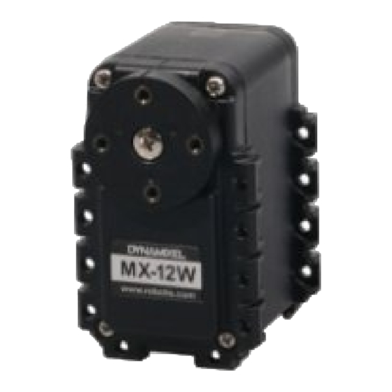
MX-12W
1. Specifications
Item
MCU
Position Sensor
Motor
Baud Rate
Resolution
Running Degree
Weight
Dimensions (W x H x D)
Gear Ratio
No Load Speed
Operating Temperature
Input Voltage
Standby Current
Command Signal
Protocol Type
Physical Connection
ID
Feedback
Material
Specifications
ARM CORTEX-M3 (72 [MHz], 32Bit)
Contactless absolute encoder (12Bit, 360 [°])
Maker : ams(www.ams.com), Part No : AS5045
Cored
8000 bps ~ 4.5 Mbps
4096 [pulse/rev]
0° ~ 360°
Endless Turn
54.6g
32 x 50 x 40 [mm]
32 : 1
470 [rev/min] (at 12 [V])
-5°C ~ +70°C
10 ~ 14.8V (Recommended : 12V)
60mA
Digital Packet
Half Duplex Asynchronous Serial Communication
(8bit, 1stop, No Parity)
TTL Level Multidrop Bus(Daisy Chain Type Connector)
0 ~ 253
Position, Temperature, Load, Input Voltage, etc
Engineering Plastic
Advertisement

Related Manuals for Robotis MX-12W


Summary of Contents for Robotis MX-12W
- Page 1 MX-12W 1. Specifications Item Specifications ARM CORTEX-M3 (72 [MHz], 32Bit) Contactless absolute encoder (12Bit, 360 [°]) Position Sensor Maker : ams(www.ams.com), Part No : AS5045 Motor Cored Baud Rate 8000 bps ~ 4.5 Mbps Resolution 4096 [pulse/rev] 0° ~ 360°...
-
Page 2: Control Table
DANGER (May cause serious injury or death) Never place items containing water, flammables, and solvents near product. Never place fingers, arms, toes, and other body parts near product during operation. Cut power off if product emits strange odors or smoke. Keep product out of reach of children. - Page 3 2. 1. 1. Area (EEPROM, RAM) The Control Table is divided into 2 Areas. Data in the RAM Area is reset to initial values when the power is reset(Volatile). On the other hand, data in the EEPROM Area is maintained even when the device is powered off(Non-Volatile).
- Page 4 Size Initial Address Data Name Description Access (Byte) Value Status Return Level Select Types of Status Return Alarm LED LED for Alarm Shutdown Shutdown Error Information Multi Turn Offset Adjust Position with Offset Resolution Divider Divider for Position Resolution 2. 3. Control Table of RAM Area Size Initial Address...
- Page 5 This address stores firmware version of DYNAMIXEL. 2. 4. 3. ID (3) The ID is a unique value in the network to identify each DYNAMIXEL with an Instruction Packet. 0~252 (0xFC) values can be used as an ID, and 254(0xFE) is occupied as a broadcast ID.
- Page 6 2. 4. 5. Return Delay Time (5) After the DYNAMIXEL receives an Instruction Packet, it delays transmitting the Status Packet Return Delay Time(5). For instance, if the Return Delay Time(5) is set to ‘10’, the Status Packet will be returned after 20[μsec] when the Instruction Packet is received. Unit Value Range Description...
- Page 7 It is the torque value of maximum output. 0 to 1,023 (0x3FF) can be used, and the unit is about 0.1%. For example, Data 1,023 (0x3FF) means that DYNAMIXEL will use 100% of the maximum torque it can produce while Data 512 (0x200) means that DYNAMIXEL will use 50% of the maximum torque.
- Page 8 Item Description OverHeating When the internal temperature is out of the range of operating temperature set in the Error Control Table Angle Limit When Goal Position is written with the value that is not between CW Angle Limit and Error CCW Angle Limit Input Voltage When the applied voltage is out of the range of operating voltage set in the Control Table...
- Page 9 For example, a DYNAMIXEL with a Real Position of 2048 with a Resolution Divider set as 4 and Multi-turn Offset as 1024 will yield a Present Position of 1535 ((2048/4) + 1024 = 1535). NOTE : This feature is only applied in multi-turn mode and will be ignored in other modes. 2.
- Page 10 : P Gain / 8 : I Gain * 1,000 / 2,048 : D Gain * 4 / 1,000 The relationship between Compliance Slop and PID Slope P Gain The less the P gain, The larger the back lash, and the weaker the amount of output near goal position.
- Page 11 The picture above is the front view of DYNAMIXEL In multi-turn mode DYNAMIXEL has a range from -28,672 to 28,672 (can turn up to 7 revolutions in either CW or CCW direction). When resolution divider is set to a different value revolutions can increase. NOTE : If it is set to Wheel Mode, Goal Position value is not used.
- Page 12 It is the present position value of DYNAMIXEL. The range of the value is 0~4095 (0xFFF), and the unit is 0.088 [°]. The picture above is the front view of DYNAMIXEL. In multi-turn mode, the range is from -28,672 to 28,672 with unit values dependent on Resolution Divider (0.088 * Resolution Divider) NOTE : In multi-turn mode, Present position depends on resolution divider and multi-turn offset For more information turn to the section on Multi Turn offset and Resolution Divider.
- Page 13 It is the size of the present voltage supplied. This value is 10 times larger than the actual voltage. For example, when 10V is supplied, the data value is 100 (0x64) If Present Voltage(42) value is out of range, Voltage Range Error Bit (Bit0) of Status Packet is returned as ‘1’ and Alarm is triggered and set the address 17 and set 1 to the Bit 0 of the address 18.
-
Page 14: Maintenance
2. 4. 30. Goal Acceleration (73) This is Goal Acceleration value. It can be used from 0~254(0xFE) and the unit is approximately 8.583 [° / sec When it is set to 0, there is no control over acceleration and moves with the maximum acceleration of the motor. - Page 15 The bearing set can also be purchased separately. As bearing set is rotating freely, therefore alignment is not required when assembling to DYNAMIXEL. 4. Reference NOTE Compatibility Guide Harness Compatibility 4. 1. Videos ROBOTIS - DYNAMIXEL MX-12W ROBOTIS - DYNAMIXEL MX-12W 4. 2. Connector Information Item Pinout DATA Diagram...
- Page 16 WARNING: Check the pinout! The pinout of DYNAMIXEL can differ from the pinout of connector manufacturer. 4. 3. Drawings Please also checkout ROBOTIS Download Center for software applications, 3D/2D CAD, and other useful resources! © 2020 ROBOTIS. Powered by Jekyll & Minimal Mistakes. www.pishrobot.com...
Need help?
Do you have a question about the MX-12W and is the answer not in the manual?
Questions and answers