Table of Contents
Advertisement
Quick Links
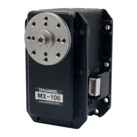
MX-106R, MX-106T
NOTE : Compliance has been replaced with PID Gains.
NOTE : Although the MX-106T (TTL) and MX-106R (RS-485) differ in communications protocols both have
the same features and perform equally. (TTL uses 3-pin connectors while RS-485 uses 4)
NOTE : In order to use Protocol 2.0, please update the firmware to V39 or above.
Manager 2.0)
Dynamixel MX Series (Protocol v2.0) F/W Recovery
Dynamixel MX Series (Protocol v2.0) F/W Recovery
WARNING : For MX-106(2.0) Protocol, please refer to the
1. Specifications
Item
MCU
Position Sensor
Specifications
ARM CORTEX-M3 (72 [MHz], 32Bit)
Contactless absolute encoder (12Bit, 360 [°])
Maker : ams(www.ams.com), Part No : AS5045
MX-106(2.0) Control Table
(Update firmware
using R+
as they are different.
Advertisement
Table of Contents


Need help?
Do you have a question about the MX-106R and is the answer not in the manual?
Questions and answers