Table of Contents
Advertisement
Quick Links
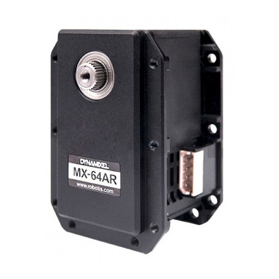
MX-64AR, MX-64AT
NOTE : Compliance has been replaced with PID Gains.
NOTE : Although the MX-64AT (TTL) and MX-64AR (RS-485) differ in communications protocols both have
the same features and perform equally. (TTL uses 3-pin connectors while RS-485 uses 4)
NOTE : In order to use Protocol 2.0, please update the firmware to V39 or above.
Manager 2.0)
Dynamixel MX Series (Protocol v2.0) F/W Recovery
Dynamixel MX Series (Protocol v2.0) F/W Recovery
WARNING : For MX-64(2.0) Protocol, please refer to the
1. Specifications
Item
MCU
Position Sensor
Specifications
ARM CORTEX-M3 (72 [MHz], 32Bit)
Contactless absolute encoder (12Bit, 360 [°])
Maker : ams(www.ams.com), Part No : AS5045
MX-64(2.0) Control Table
(Update firmware
using R+
as they are different.
Advertisement
Table of Contents

Subscribe to Our Youtube Channel
Related Manuals for Robotis MX-64AR


Summary of Contents for Robotis MX-64AR
- Page 1 MX-64AR, MX-64AT NOTE : Compliance has been replaced with PID Gains. NOTE : Although the MX-64AT (TTL) and MX-64AR (RS-485) differ in communications protocols both have the same features and perform equally. (TTL uses 3-pin connectors while RS-485 uses 4) NOTE : In order to use Protocol 2.0, please update the firmware to V39 or above.
- Page 2 RS485 / TTL Multidrop Bus 254 ID (0 ~ 253) Feedback Position, Temperature, Load, Input Voltage, etc Full Metal Gear Material Engineering Plastic(Front, Middle, Back) Metal(Front) Standby Current 100 [mA] Applies to alumium housing products(MX-28AR/AT, MX-64AR/AT, MX-106R/T). DANGER (May cause serious injury or death)
-
Page 3: Performance Graph
Never place items containing water, flammables, and solvents near product. Never place fingers, arms, toes, and other body parts near product during operation. Cut power off if product emits strange odors or smoke. Keep product out of reach of children. Check the power polarity before wiring. -
Page 4: Control Table
Generally, Max Torque of the Performance Graph is less than the Stall Torque. CAUTION : When supplying power It is recommended using ROBOTIS controller or SMPS2DYNAMIXEL. Do not connect or disconnect DYNAMIXEL when power is being supplied. 2. Control Table The Control Table is a structure of data implemented in the device. - Page 5 2. 1. 4. Initial Value Each data in the Control Table is restored to initial values when the device is turned on. Default values in the EEPROM area are initial values of the device (factory default settings). If any values in the EEPROM area are modified by a user, modified values will be restored as initial values when the device is turned on.
- Page 6 Size Initial Address Data Name Description Access (Byte) Value Moving Speed Moving Speed(Moving Velocity) Torque Limit Torque Limit(Goal Torque) ADD 14&15 Present Position Present Position Present Speed Present Speed Present Load Present Load Present Voltage Present Voltage Present Temperature Present Temperature Registered If Instruction is registered Moving...
- Page 7 Baudrate(BPS) = 2,000,000 / (Value + 1) Value Baud Rate(bps) Margin of Error 0.000 [%] 0.000 [%] 500,000 0.000 [%] 400,000 0.000 [%] 250,000 0.000 [%] 200,000 0.000 [%] 115200 -2.124 [%] 34(Default) 57600 0.794 [%] 19200 -0.160 [%] 9600 -0.160 [%] NOTE : Less than 3% of the baud rate error margin will not affect to UART communication.
- Page 8 Operation Type Operation Type CW / CCW CW / CCW Wheel Mode both are 0 Joint Mode neither are 0 Multi-turn Mode both are 4095 The wheel mode can be used to wheel-type operation robots since motors of the robots spin infinitely.
- Page 9 Value Responding Instructions Description PING Instruction Status Packet will be returned only for READ Instruction READ Instruction All Instructions Status Packet will be returned for all Instructions NOTE : If the ID of Instruction Packet is set to Broad Cast ID(0xFE), Status Packet will not be returned for READ and WRITE Instructions regardless of Status Return Level.
- Page 10 Adjusts offset position. This offset value is added to the Present Position(36). Initial value is 0 and the range is from -24,576 to 24,576. DYNAMIXEL with a Present position of 2,048 with an offset of 1,024 will return an adjusted Present position of 3,072.
- Page 11 2. 4. 14. Torque Enable (24) Value Description 0(Default) Turn off the torque Turn on the torque and lock EEPROM area 2. 4. 15. LED (25) Turn on or turn off the LED on DYNAMIXEL. Description 0(Default) Turn OFF the LED Turn ON the LED NOTE : The LED indicates present status of the device.
- Page 12 The relationship between Compliance Slop and PID Slope P Gain The less the P gain, The larger the back lash, and the weaker the amount of output near goal position. At some extent, it is like a combined concept of margine and slope. It does not exactly match the previous concept of compliance.
- Page 13 Join Mode, Multi-Turn mode It is a moving speed to Goal Position. 0~1023 (0X3FF) can be used, and the unit is about 0.114rpm. If it is set to 0, it means the maximum rpm of the motor is used without controlling the speed.
- Page 14 NOTE : In multi-turn mode, Present position depends on resolution divider and multi-turn offset For more information turn to the section on Multi Turn offset and Resolution Divider. 2. 4. 21. Present Speed (38) Is the current moving speed. 0 ~ 2,047 (0x000 ~ 0x7FF) can be used. If a value is in the rage of 0 ~ 1,023 then the motor rotates to the CCW direction.
- Page 15 Value Description REG_WRITE instruction is not received REG_WRITE instruction is received NOTE : If ACTION instruction is executed, the value will be changed to 0. 2. 4. 26. Moving (46) Value Description Goal position command execution is completed Goal position command execution is in progress 2.
- Page 16 2. 4. 31. Torque Control Mode Enable (70) Value Meaning Turn off the torque mode. Executes Joint mode or Wheel mode Turn on the torque mode. Cannot control the position or moving speed but only Torque When Torque Control Mode Enable is 1, DYNAMIXEL behaves like the followings DYNAMIXEL does not control position or velocity.
-
Page 17: How To Assemble
3. How to Assemble 3. 1. Optional Frames FR05-B101 FR05-F101 and FR05-X101 FR05-H101 FR05-S101 3. 2. Horns HN05-I102 HN05-N101... -
Page 18: Maintenance
3. 3. Combination Structures 4. Maintenance 4. 1. Horn and Bearing Replacement The horn is installed on the front wheel gear serration of the DYNAMIXEL whereas the bearing set is installed on the back. 4. 1. 1. Installing the Horn... - Page 19 Place the thrust horn washer into the actuator before inserting the horn. You must carefully align the horn to the wheel gear serration by aligning dots. Once alignment is properly done, gently push the center of the horn toward the actuator. Make sure that the horn washer is in place as you tighten the bolt.
-
Page 20: Connector Information
Operation of this equipment in a residential area is likely to cause harmful interference in which case the user will be required to correct the interference at his own expense. WARNING Any changes or modifications not expressly approved by the manufacturer could void the user’s authority to operate the equipment. - Page 21 ROBOTIS FAQ-DXL Gear Replacement (MX-64/MX-106) ROBOTIS FAQ-DXL Gear Replacement (MX-64/MX-106) 5. 4. Drawings MX-64AT_AR DWG Download MX-64AT_AR PDF Download MX-64AT_AR STEP Download MX-64T DWG Download MX-64T PDF Download MX-64T STEP Download MX-64T IGES Download MX-64R DWG Download MX-64R PDF Download...
- Page 22 In case of DIRECTION485 Level = Low: The signal of D+ and D- is output to RxD WARNING: Check the pinout! The pinout of DYNAMIXEL can differ from the pinout of connector manufacturer. © 2020 ROBOTIS. Powered by Jekyll & Minimal Mistakes. www.pishrobot.com...
Need help?
Do you have a question about the MX-64AR and is the answer not in the manual?
Questions and answers