Table of Contents
Advertisement
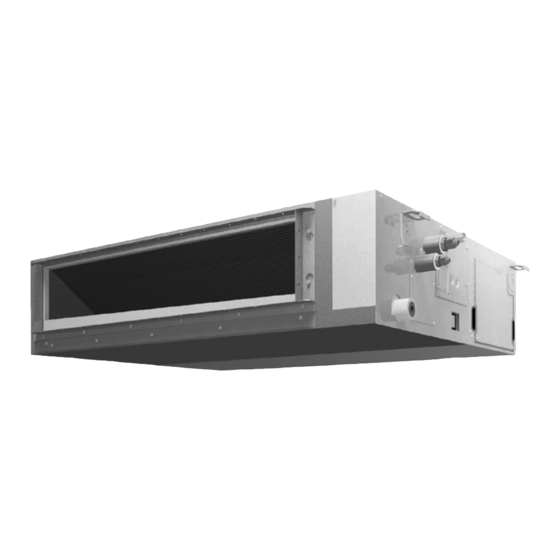
SPLIT SYSTEM
MODELS
Ceiling-mounted Duct type
FBQ18TBVJU
FBQ42TBVJU
FBQ24TBVJU
FBQ48TBVJU
FBQ30TBVJU
FBQ36TBVJU
Read these instructions carefully before installation.
Keep this manual in a handy place for future reference.
This manual should be left with the equipment owner.
Lire soigneusement ces instructions avant l'installation.
Conserver ce manuel à portée de main pour référence ultérieure.
Ce manuel doit être donné au propriétaire de l'équipement.
Lea cuidadosamente estas instrucciones antes de instalar.
Guarde este manual en un lugar a mano para leer en caso de tener alguna duda.
Este manual debe permanecer con el propietario del equipo.
INSTALLATION MANUAL
Air Conditioners
English
Français
Español
Advertisement
Table of Contents

Related Manuals for Daikin FBQ42TBVJU


Summary of Contents for Daikin FBQ42TBVJU
- Page 1 INSTALLATION MANUAL SPLIT SYSTEM Air Conditioners MODELS Ceiling-mounted Duct type FBQ18TBVJU FBQ42TBVJU FBQ24TBVJU FBQ48TBVJU English FBQ30TBVJU FBQ36TBVJU Français Read these instructions carefully before installation. Keep this manual in a handy place for future reference. This manual should be left with the equipment owner.
-
Page 2: Table Of Contents
CONTENTS DANGER • Refrigerant gas is heavier than air and replaces oxygen. 1. SAFETY CONSIDERATIONS ........1 A massive leak can lead to oxygen depletion, especially 2. BEFORE INSTALLATION ..........3 in basements, and an asphyxiation hazard could occur leading to serious injury or death. 3. - Page 3 Daikin are used, fire or explosion may occur. (b) Where corrosive gas, such as sulfurous acid gas, is • Do not install in a wet room such as a bathroom or laundry produced.
-
Page 4: Before Installation
2. BEFORE INSTALLATION (10) Wire sealing (11) Washer for Name (9) Washer clamp material hanger bracket When unpacking the indoor unit or moving the unit after unpacked, hold the hanger brackets (4 locations) and do Quantity 4 pcs. 2 sheets 8 pcs. -
Page 5: Selection Of Installation Location
Points of the operation explanation Check Items to be checked In case of defective column In addition to the general usage, since the items in the Danger in case of operation manual with the WARNING and Is grounding completed? leakage CAUTION marks are likely to result in human bodily Are the sizes of electric injuries and property damages, it is neces sary not only... -
Page 6: Preparation Before Installation
4. PREPARATION BEFORE INSTALLATION [ Required installation space [in. (mm)] ] Figures indicate the minimum required installation space. (1) Check the relation of location between the ceiling opening and the indoor unit suspension bolts. • Provide one of the following service spaces for the maintenance and inspection of the control box and drain pump or for other services. - Page 7 (5) Install the suspension bolts. Control box • Use either a M8-M10 size bolt or equivalent. Use hole-in-anchors for the existing bolts and embed- ded inserts or foundation bolts for new bolts, and fix the Ceiling indoor unit firmly to the building so that it may withstand the weight of the unit.
-
Page 8: Installation Of Indoor Unit
<05-48 type> [ Washer fixing ] Suction flange Upper nut Washer clamp (9) (Accessory) Washer for Insert hanger bracket (11) (Accessory) Replacement Chamber cover Fig. 7 <54 type> • Keep the discharge covered with a protective sheet to pre- Suction flange vent weld spatter and other foreign materials from entering the indoor unit and damaging the resin drain pan. -
Page 9: Refrigerant Piping Work
6. REFRIGERANT PIPING WORK Table 2 Piping Tightening Dimension for • For the outdoor unit refrigerant piping, refer to the installa- Flare shape size torque processing flare [in. (mm)] tion manual attached to the outdoor unit. [in. (mm)] [lbf·ft. (N·m)] A [in. - Page 10 • After leak test, referring to Fig. 11, insulate both the • Before brazing refrigerant piping, have nitrogen flow gas and liquid piping connection with the attached joint through the refrigerant piping and substitute air with insulating material (4) and (5) to prevent the pipings from nitrogen (NOTE 1) (Refer to Fig.
-
Page 11: Drain Piping Work
7. DRAIN PIPING WORK • Wrap the vinyl tape around the end of the metal clamp (1) so that the sealing material (Large) (6) to be used at (1) Carry out drain piping. the next process may not be damaged with the clamp Carry out drain piping so that drainage is ensured. - Page 12 < Caution to be taken when carrying out upward CAUTION drain piping (Refer to Fig. 16) > • To avoid the attached drain hose (2) getting excessive • The maximum height of the drain riser is 26-9/16 in. force, do not bend nor twist it. (675 mm).
- Page 13 (2) After piping is finished, check if the drain flows • Do not apply external force to the float switch. (It smoothly. may result in malfunction) • Do not touch the drain pump. [When the electric wiring work is finished] Touching the drain pump may cause electric shock.
-
Page 14: Duct Work
8. DUCT WORK 9. ELECTRIC WIRING WORK Pay the utmost attention to the following items and con- 9-1 GENERAL INSTRUCTIONS duct the duct work. • Make certain that all electric wiring work is carried out by • Check that the duct is not in excess of the setting range of qualified personnel according to the applicable legislation external static pressure for the unit. - Page 15 MIN. 187V 0.49 FBQ36TBVJU • Do not carry out soldering finish when stranded wires are (364) used. (Otherwise, the loosening of wires may result in 0.49 FBQ42TBVJU (364) abnormal heat radiation.) 0.49 FBQ48TBVJU (364) MCA: Minimum Circuit Ampacity (A); MOP: Maximum Overcurrent Protective Device (A) HP: Fan Motor Rated Output (Hp (W));...
- Page 16 Hook WARNING Conduit mounting • When wiring, form the wirings orderly so that the control plate (12) box cover can be securely fastened. If the control box cover Screws (2 locations) is not in place, the wirings may come out or be sandwiched by the box and the cover and cause electric shock or fire.
- Page 17 (5) Mount the control box cover and wrap the wire seal- < No. 2 system: When using 2 remote controllers > ing material (small) (10) so that the wiring through Power supply Outdoor unit hole will be covered by the sealing material. single phase 60Hz 208/230V •...
-
Page 18: Field Setting
10. FIELD SETTING 9-7 FOR CENTRALIZED CONTROL • When centralized equipment (such as centralized control- CAUTION ler) is used for control, it is required to set the group No. on the remote controller. Before carrying out field setting, check the items mentioned in For details, refer to the manuals attached to the centralized (1) Items to be checked after the installation work is com- equipment. - Page 19 10-1 Settings for external static pressure CAUTION • Make settings in either method (a) or method (b). • If airflow pathway changes, such as duct and discharge (a) Make settings with Air volume automatic adjust- changes, are made after air volume adjustments, be sure to ment function.
-
Page 20: Test Operation
11. TEST OPERATION 10-4 SETTING FILTER SIGN • A message to inform the air filter cleaning time will be indi- • After cleaning the indoor unit inside, carry out test operation cated on the remote controller. according to installation manual attached to the outdoor •... - Page 21 Daikin Texas Technology Park, 19001 Kermier Road, Waller, TX, 77484, U.S.A. 3P493125-7F EM21A037A [2209] HT...
Need help?
Do you have a question about the FBQ42TBVJU and is the answer not in the manual?
Questions and answers