
Related Manuals for W.E.S.T. Elektronik PAM-195-P-S3


Summary of Contents for W.E.S.T. Elektronik PAM-195-P-S3
- Page 1 Technical Documentation PAM-195-P-S3 Power amplifier for directional valves with integrated power limitation function...
-
Page 2: Table Of Contents
Output signal adaption ............................27 5.5.1 CC (Characteristics linearization) ......................27 5.5.2 MIN (Overlap compensation) ........................28 5.5.3 MAX (Output scaling) ..........................28 5.5.4 TRIGGER (Threshold value of MIN function) ..................... 28 Parameters of the power stage........................... 29 Page 2 of 35 PAM-195-P-S3 05.06.2020... - Page 3 Differences to former product generations ......................33 6.3.1 Baudrate of the serial Interface ........................33 6.3.2 Output current adjustment / MIN_MAX / RCURR ..................33 Description of the command structure ........................ 34 Notes ..................................35 Page 3 of 35 PAM-195-P-S3 05.06.2020...
-
Page 4: General Information
1 General Information Order Number PAM-195-P-S3 - power amplifier for directional valves with integrated power limitation function Scope of supply The scope of supply includes the module plus the terminal blocks which are a part of the housing. The Profibus plug, interface cables and further parts which may be required should be ordered separately. -
Page 5: Symbols Used
We reserve the right to make technical modifications due to further development of the product described in this manual. The technical information and dimensions are non-binding. No claims may be made based on them. This document is protected by copyright. Page 5 of 35 PAM-195-P-S3 05.06.2020... -
Page 6: Safety Instructions
The module may not be used in an explosive environment. To ensure adequate cooling the ventilation slots must not be covered. The device must be disposed of in accordance with national statutory provisions. Page 6 of 35 PAM-195-P-S3 05.06.2020... -
Page 7: Characteristics
Free parameterization of RAMPS, MIN und MAX, output current, DITHER (frequency, amplitude) Nominal output current range: 0,5… 2,6 A Simple and application orientated parameter settings via WPC-software Failure monitoring and extended function check Page 7 of 35 PAM-195-P-S3 05.06.2020... -
Page 8: Device Description
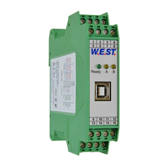
Made in Germany Date: Add.: W.E.ST. Elektronik D-41372 Niederkrüchten Homepage: http://www.w-e-st.de Typenschild und Anschlussbelegung Type plate and terminal pin assignment LEDs Ready Klemmblöcke (steckbar) Terminals (removable) interface 9 10 11 12 14 15 16 Page 8 of 35 PAM-195-P-S3 05.06.2020... -
Page 9: Use And Application
Switched inductances (relays and valve coils connected to the same power supply) must always be provided with appropriate overvoltage protection directly at the coil. Page 9 of 35 PAM-195-P-S3 05.06.2020... -
Page 10: Commissioning
CAUTION! The drive can now leave its position and move to an end position with full Activating ENABLE speed or the pressure can reach maximum. Take safety measures to prevent per- sonal injury and damage. Page 10 of 35 PAM-195-P-S3 05.06.2020... -
Page 11: Range Of Applications
In this kind of use several devices get a signal for the power consumption of the whole system as feedback. So single valves can open without limitation. Even if the system reaches its borderline for overload, all valves will be limited uniformly. Page 11 of 35 PAM-195-P-S3 05.06.2020... -
Page 12: Function Modes And Technical Description
Current to the solenoid; the intensity is proportional to the actual output current. LED in the right position = Power limitation; the LED indicates, whether the device is in power limitation range or not. Page 12 of 35 PAM-195-P-S3 05.06.2020... -
Page 13: Typical System Structure
This minimal system consists of the following components: (*1) proportional valve (*2) hydraulic cylinder (*3) power amplifier PAM-195-P-S3 (*4) interface to PLC with analogue and digital signals (*5) power input, from pressure sensor or pump Method of operation This power amplifier is controlled by an analogue signal (from the PLC, from a joystick or a potentiometer). An ENABLE signal (typically 24V) activates the module and the READY output indicates this, if no internal or ex- ternal error was detected. -
Page 14: Input And Output Signals
By deactivating error signals are reset. Direction input: PIN 6 Switching direction (changing solenoids). READY output: PIN 5 Module is ready, no errors are detected OFF: ENABLE (PIN 15) is deactivated or an error is detected. Page 14 of 35 PAM-195-P-S3 05.06.2020... -
Page 15: Circuit Diagram
Circuit diagram Page 15 of 35 PAM-195-P-S3 05.06.2020... -
Page 16: Typical Wiring
Magnet A / Solenoid A 12 V / 24 V Direction Ready Spannungsversorgung / Power Supply Schirm / Screen V ref. Analoger Sollwert / Analogue command signal Analoges Sensorsignal / Analogue feedback signal Enable Page 16 of 35 PAM-195-P-S3 05.06.2020... -
Page 17: Input Connection (Examples)
8V PIN 12 AIN:W 1000 800 0 V ( 0... 100%) +In PIN 9 AIN:W 2000 800 4000 V ( +/-100%) -In PIN 10 GND PIN 11 3 wire connection e.g. for HAWE valves solenoid-A solenoid-B Page 17 of 35 PAM-195-P-S3 05.06.2020... -
Page 18: Technical Data
PE: direct via DIN rail Protection class IP20 -20… 60 Temperature range [°C] -20 …70 Storage temperature [°C] Humidity <95 (not condensing) Vibration IEC 60068-2-6 (category C) EN 61000-6-2: 8/2005 EN 61000-6-4: 6/2007 ; A1:2011 Page 18 of 35 PAM-195-P-S3 05.06.2020... -
Page 19: Parameter
Command signal four quadrant ramp times RA:2 RA:3 RA:4 Power limitation function PLV:A 10000 0.01 % Power limitation factor PLV:B 10000 0.01 % PLT1:A 5000 0.1 ma Dynamic of the power limitation PLT1:B 5000 0.1 ms Page 19 of 35 PAM-195-P-S3 05.06.2020... - Page 20 Parameters of the power stage CURRENT 1000 Rated solenoid current DAMPL 0.01 % Dither amplitude DFREQ Dither frequency 2604 PWM frequency Current loop auto adjustment PPWM P-Gain of the current loop IPWM I-Gain of the current loop Page 20 of 35 PAM-195-P-S3 05.06.2020...
-
Page 21: Basic Parameters
(AIN) for differing signal ranges. For adapting the feedback input some more parameters are provided in EASY mode, helping to scale it to the chosen pressure range and display the parameter in Bar. Page 21 of 35 PAM-195-P-S3 05.06.2020... -
Page 22: Sens (Failure Monitoring)
5.2.6 SOLENOIDS (One or two solenoids) Command Parameters Unit Group SOLENOIDS X x= 1|2 This parameter allows you to adapt the amplifier to valves with one solenoid (e.g. pressure valves) or to such with two solenoids (directional valves). Page 22 of 35 PAM-195-P-S3 05.06.2020... -
Page 23: Pol (Output Polarity)
0...10 V or 10… 0 V just as the current ones from 4…20 mA and 20… 4 mA, used for 0… 100% demand value. This command is only active if AINMODE is set to EASY. Page 23 of 35 PAM-195-P-S3 05.06.2020... -
Page 24: Ain (Analogue Input Scaling)
(60% offset for 12mA as zero position). AIN:I -5… 5 V Voltages input: Usable -10… 10V (20V) for a working range of -100… 100% (two solenoids). AIN:I 2000 1000 Really used are -5… 5V (10V). Multiplying factor 2. Page 24 of 35 PAM-195-P-S3 05.06.2020... -
Page 25: Sys_Range (Rated Pressure Of The System)
-60000… 60000 mbar AINMODE=EASY Via this parameter an offset value for the pressure sensor can be preset. That means you can do a shift of the zero point of the feedback signal with it. Page 25 of 35 PAM-195-P-S3 05.06.2020... -
Page 26: Ra (Ramp Function)
Typical used values are in the range of 5… 50ms. Attention: Because of internal calculations the value is parameterizable only stepwise. Always the next possi- ble higher step is chosen. Page 26 of 35 PAM-195-P-S3 05.06.2020... -
Page 27: Output Signal Adaption
For the input of the characteristics linearization, the WPC-300 program provides a table and a graphic data input. The input signal is mapped on to the X-axis and the output signal is mapped on to the Y-axis. Page 27 of 35 PAM-195-P-S3 05.06.2020... -
Page 28: Min (Overlap Compensation)
This dead band is necessary, in order to avoid unrequested activations caused by small variations of the input signal. If this module is used in a position controls, the TRIGGER value should be reduced (typical: 1…10). Page 28 of 35 PAM-195-P-S3 05.06.2020... -
Page 29: Parameters Of The Power Stage
The DITHER frequency should not be confused with the PWM frequency. In some proportional valve documentations a mistake is done by the definition of the DITHER / PWM frequency. It is recognizable by missing information about the DITHER amplitude. Page 29 of 35 PAM-195-P-S3 05.06.2020... -
Page 30: Pwm (Pwm Frequency)
5.6.5 ACC (Auto adaptation of the closed loop current controller) Command Parameters Unit Group x= ON|OFF Operation mode of the closed loop current control. In automatic mode PPWM and IPWM are calculated depending on the preset PWM-frequency. OFF: Manual adjustment. Page 30 of 35 PAM-195-P-S3 05.06.2020... -
Page 31: Ppwm (Solenoid Current Controller P Gain)
Command value to current controller Output current of solenoid A Output current of solenoid B The process data are the variable values which can be continuously observed on the monitor or on the oscillo- scope. Page 31 of 35 PAM-195-P-S3 05.06.2020... -
Page 32: Appendix
Internal data error: execute the command / press the button SAVE to delete the data error. The system reloads the DEFAULT data. With the WPC-300 operating program the failure can be localized directly via the monitor. Page 32 of 35 PAM-195-P-S3 05.06.2020... -
Page 33: Differences To Former Product Generations
The current command now needs the rated current value of the valve/solenoid. All parameters: MIN, MAX, DAMPL are in % and directly related to the rated current. The advantages are clear and simple adjustments, fix relationship of the dither amplitude and an exact output current adjustment. Page 33 of 35 PAM-195-P-S3 05.06.2020... -
Page 34: Description Of The Command Structure
Examples: nnnn = “MIN”, i = “A” and x = “2000” MIN:A 2000 nnnn = „OFFSET“ and x = „50“ OFFSET 50 nnnn = “C”, i = “IC” and x = “2000” C:IC 2000 Page 34 of 35 PAM-195-P-S3 05.06.2020... -
Page 35: Notes
7 Notes Page 35 of 35 PAM-195-P-S3 05.06.2020...
Need help?
Do you have a question about the PAM-195-P-S3 and is the answer not in the manual?
Questions and answers