
Related Manuals for W.E.S.T. Elektronik PAM-199-P


Summary of Contents for W.E.S.T. Elektronik PAM-199-P
- Page 1 Technical Documentation PAM-199-P Power amplifier for all typical proportional valves...
-
Page 2: Table Of Contents
PIN:6 (Choice of the additional function of S1/PIN 6) ..................32 USCALE (Output current scaling depending on PIN:6) ..................32 5.10 ENABLE_B (Switching of the ENABLE Function) ....................32 5.11 LIM (Signal monitoring) ............................33 Page 2 of 48 PAM-199-P 05.06.2020... - Page 3 PPWM (Solenoid current controller P gain) ......................45 5.37 IPWM (Solenoid current controller I gain) ......................45 5.38 PROCESS DATA (Monitoring)..........................46 Appendix ..................................47 Failure monitoring ............................... 47 Troubleshooting ..............................47 Notes ..................................48 Page 3 of 48 PAM-199-P 05.06.2020...
-
Page 4: General Information
1 General Information Order Number PAM-199-P - Power amplifier for proportional directional, pressure or throttle valves with analog command signal input Alternative / extended products PAM-199-P-ETC - Power amplifier for proportional directional, pressure or throttle valves with EtherCAT – interface... -
Page 5: Symbols Used
We reserve the right to make technical modifications due to further development of the product described in this manual. The technical information and dimensions are non-binding. No claims may be made based on them. This document is protected by copyright. Page 5 of 48 PAM-199-P 05.06.2020... -
Page 6: Safety Instructions
The module may not be used in an explosive environment. To ensure adequate cooling the ventilation slots must not be covered. The device must be disposed of in accordance with national statutory provisions. Page 6 of 48 PAM-199-P 05.06.2020... -
Page 7: Characteristics
Free parameterization of RAMPS, MIN und MAX, output current, DITHER (frequency, amplitude) Nominal output current range: 0.5… 2.6 A Simple and application orientated parameter settings via WPC-software Failure monitoring and extended function check Page 7 of 48 PAM-199-P 05.06.2020... -
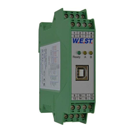
Page 8: Device Description
Made in Germany Date: Add.: W.E.ST. Elektronik D-41372 Niederkrüchten Homepage: http://www.w-e-st.de Typenschild und Anschlussbelegung Type plate and terminal pin assignment LEDs Ready Klemmblöcke (steckbar) Terminals (removable) Interface 9 10 11 12 14 15 16 Page 8 of 48 PAM-199-P 05.06.2020... -
Page 9: Use And Application
Switched inductances (relays and valve coils connected to the same power supply) must always be provided with appropriate overvoltage protection directly at the coil. Page 9 of 48 PAM-199-P 05.06.2020... -
Page 10: Commissioning
CAUTION! The drive can now leave its position and move to an end position with full Activating ENABLE speed or the pressure can reach maximum. Take safety measures to prevent per- sonal injury and damage. Page 10 of 48 PAM-199-P 05.06.2020... -
Page 11: Function Modes And Technical Description
LED in the middle position = Current, Channel A; the intensity is proportional to the output current LED in the right position = Current, Channel B; the intensity is proportional to the output current Page 11 of 48 PAM-199-P 05.06.2020... -
Page 12: Control Of Directional Valves (195)
READY output and a flashing READY LED. To leave the error state the ENABLE has to be reset. The output current is closed loop controlled whereby a high accuracy and a good dynamic will be obtained. All custom proportional valves (up to 2.6A) may be controlled with this power amplifier. Page 12 of 48 PAM-199-P 05.06.2020... -
Page 13: Input And Output Signals
Output current depends on parameter USCALE; ramp function is deactivated. Output current is not scaled by USCALE, ramp function is activated. PIN 5 READY output: Module is ready, no errors are detected OFF: ENABLE is deactivated or an error is detected. Page 13 of 48 PAM-199-P 05.06.2020... -
Page 14: Circuit Diagram
4.3.4 Circuit diagram Page 14 of 48 PAM-199-P 05.06.2020... -
Page 15: Typical Wiring
4.3.5 Typical wiring Solenoid B Solenoid A Power supply Ready Shield V ref. Analogue command signal (-10... 10V) Enable Page 15 of 48 PAM-199-P 05.06.2020... -
Page 16: Parameter List
Trigger point for activating the MIN value CURRENT 1000 Nominal output current DAMPL 0,01% Dither amplitude DFREQ Dither frequency 2604 PWM frequency. Automatic adjustment of PPWM and IPWM parameters PPWM Control parameter for the current control loop IPWM Page 16 of 48 PAM-199-P 05.06.2020... -
Page 17: Control Of Two Throttle And / Or Pressure Valves (196)
READY output and a flashing READY LED. To leave the error state the ENABLE has to be reset. The output current is closed loop controlled whereby a high accuracy and a good dynamic will be obtained. All custom proportional valves (up to 2.6A) may be controlled with this power amplifier. Page 17 of 48 PAM-199-P 05.06.2020... -
Page 18: Input And Output Signals
Enable Input Channel B (dependent on ENABLE_B): PIN 6 General enabling of the application of Channel B. READY output: PIN 5 No internal or external errors are detected. OFF: Both power stages are deactivated or an error is detected. Page 18 of 48 PAM-199-P 05.06.2020... -
Page 19: Circuit Diagram
4.4.4 Circuit diagram Page 19 of 48 PAM-199-P 05.06.2020... -
Page 20: Typical Wiring
4.4.5 Typical wiring Solenoid B Solenoid A Enable B Ready Power Supply Shield Analogue command Reference voltage signal A Analogue command signal B Enable (A) Page 20 of 48 PAM-199-P 05.06.2020... -
Page 21: Parameter List
Dither amplitudes. Related to the nominal output current. DAMPL:B 0,01 % DFREQ:A Dither frequency DFREQ:B PWM:A 2604 PWM frequency PWM:B 2604 Automatic adjustment of PPWM and IPWM parameters PPWM:A Parameters for the closed loop current controllers PPWM:B IPWM:A IPWM:B Page 21 of 48 PAM-199-P 05.06.2020... -
Page 22: Control Of Proportional Valves By Preprogrammed Values And Ramp Times (197)
READY output and a flashing READY LED. To leave the error state the ENABLE has to be reset. The output current is closed loop controlled whereby a high accuracy and a good dynamic will be obtained. All custom proportional valves (up to 2,6A) may be controlled with this power amplifier. Page 22 of 48 PAM-199-P 05.06.2020... -
Page 23: Input And Output Signals
Connection Digital inputs and outputs Enable Input: PIN 15 General enabling of the application. READY output: PIN 5 No internal or external errors are detected OFF: ENABLE is deactivated or an error is detected Page 23 of 48 PAM-199-P 05.06.2020... -
Page 24: Circuit Diagram
4.5.4 Circuit diagram Page 24 of 48 PAM-199-P 05.06.2020... -
Page 25: Typical Wiring
4.5.5 Typical wiring Solenoid B Solenoid A Ready Power Supply Shield Reference Digital inputs for command voltage value selection Enable Page 25 of 48 PAM-199-P 05.06.2020... -
Page 26: Parameter List
Trigger point for activating the MIN value CURRENT 1000 Nominal output current DAMPL 0,01% Dither amplitude DFREQ Dither frequency 2604 PWM frequency. Automatic adjustment of PPWM and IPWM parameters PPWM Control parameter for the current control loop IPWM Page 26 of 48 PAM-199-P 05.06.2020... -
Page 27: Input Connection (Examples)
0 V (für 0... 100%) +In PIN 9 AIN:W 2000 800 4000 V (für +/-100%) -In PIN 10 GND PIN 11 Directional valves with 3 wire connection ( Mode 195 / 197) A-Solenoid for example: Hawe B-Solenoid Page 27 of 48 PAM-199-P 05.06.2020... -
Page 28: Technical Data
< 95 (non-condensing) Vibration resistance IEC 60068-2-6 (Category C) Connections Communication USB type B Plug connectors 4 x 4-pole terminal blocks via the DIN mounting rail EN 61000-6-2: 8/2005 EN 61000-6-4: 6/2007 + A1:2011 Page 28 of 48 PAM-199-P 05.06.2020... -
Page 29: Parameter Description
Either German or English can be selected for the help texts in the WPC-300 program. CAUTION: After changing the language settings the parameter list has to be updated by pressing the speed button “ID”. Page 29 of 48 PAM-199-P 05.06.2020... -
Page 30: Mode (Switching Between Parameter Groups)
READY output. Deactivating is possible especially for troubleshooting. AUTO MODE: The module checks each second the actual failure status, which will (in case of a per- sistent error) trigger the LED and the READY output for a short time. Page 30 of 48 PAM-199-P 05.06.2020... -
Page 31: Ccmode (Activation Of The Characteristic Linearization)
RDY | SOL This parameter defines the functionality of digital input PIN:6 RDY: Standard READY output. SOL: Detection of the activated solenoid. 1 = solenoid is active 0 = solenoid A is active. Page 31 of 48 PAM-199-P 05.06.2020... -
Page 32: Pin:6 (Choice Of The Additional Function Of S1/Pin 6)
PIN 15 enables both output channels. If set to ON, digital input PIN 15 enables only channel A and digital input PIN 6 enables channel B. If only one solenoid is to be controlled, ENABLE_B has to be set to ON and only the corresponding digital input has to be switched on. Page 32 of 48 PAM-199-P 05.06.2020... -
Page 33: Lim (Signal Monitoring)
If the input signal gets higher than 95 % or lower than 5%, it leaves the permitted range and the outputs will switch off. 100% error range for unipolar signals working range error range for bipolar signals -100% Page 33 of 48 PAM-199-P 05.06.2020... -
Page 34: Pol (Output Polarity)
By the use of this command the type of input signal may be chosen between voltage (0...10 V or +/- 10 V) or current (4…20mA). If current is chosen, the shunt will be activated automatically. Page 34 of 48 PAM-199-P 05.06.2020... -
Page 35: Ain (Analogue Input Scaling)
Really used are 1… 9V (8V) for 100% with 10% offset. AIN:I 2000 C 4… 20 mA Current input: theoretically usable range 0… 20mA for a working range of 0… 100% (one solenoids). AIN:I 1250 1000 2000 C Really usable are 4… 20mA (16mA). Page 35 of 48 PAM-199-P 05.06.2020... -
Page 36: Aa (Ramp Function/Acceleration Time)
Two quadrant ramp function. The first quadrant means the ramp up and the second quadrant means the ramp down time. The ramp time is related to 100 % signal step. AA:UP AA:DOWN AB:UP AB:DOWN Page 36 of 48 PAM-199-P 05.06.2020... -
Page 37: Aa (Ramp Function)
This command allows the switching between a set point related ramp function (SD), which makes it possible to assign an individual ramp time for each command value, and a four quadrant ramp function (4Q) with set point independent ramp times for acceleration and deceleration in both directions. Page 37 of 48 PAM-199-P 05.06.2020... -
Page 38: S (Presetting Command Values)
For example: if you choose set point S:1 also ramp time RA:1 is chosen. RMODE = 4Q Four quadrants ramp function. See command AA (chapter 5.18) S:1 and RA:1 S:2 and RA:2 S:3 and RA:3 S:4 and RA:4 Page 38 of 48 PAM-199-P 05.06.2020... -
Page 39: Cca (Characteristics Linearization Channel A)
For the input of the characteristics linearization, the WPC-300 program provides a table and a graphic data input. The input signal is mapped on to the X-axis and the output signal is mapped on to the Y-axis. Page 39 of 48 PAM-199-P 05.06.2020... -
Page 40: Cc (Characteristics Linearization)
For the input of the characteristics linearization, the WPC-300 program provides a table and a graphic data input. The input signal is mapped on to the X-axis and the output signal is mapped on to the Y-axis. Page 40 of 48 PAM-199-P 05.06.2020... -
Page 41: Min (Overlap Compensation)
CAUTION: If the MIN value is set too high, it influences the minimal velocity, which cannot be adjusted any longer. 100% Eingang / Input TRIGGER This dead band is necessary, in order to avoid unrequested activations caused by small variations of the input signal. Page 41 of 48 PAM-199-P 05.06.2020... -
Page 42: Min (Overlap Compensation)
This dead band is necessary, in order to avoid unrequested activations caused by small variations of the input signal. If this module is used in a position controls, the TRIGGER value should be reduced (typical: 1…10). Page 42 of 48 PAM-199-P 05.06.2020... -
Page 43: Current (Nominal Output Current)
The DITHER frequency should not be confused with the PWM frequency. In some proportional valve documentations a mistake is done by the definition of the DITHER / PWM frequency. It is recognizable by missing information about the DITHER amplitude. Page 43 of 48 PAM-199-P 05.06.2020... -
Page 44: Pwm (Pwm Frequency)
ACC (Auto adaptation of the closed loop current controller) Command Parameters Unit Group FUNCTION x= ON|OFF Operation mode of the closed loop current control. In automatic mode PPWM and IPWM are calculated depending on the preset PWM-frequency. OFF: Manual adjustment. Page 44 of 48 PAM-199-P 05.06.2020... -
Page 45: Ppwm (Solenoid Current Controller P Gain)
Typical values are: PPWM = 1… 3 and IPWM = 40… 80. If the PWM frequency is > 1000 Hz, the default values of PPWM = 7 and IPWM = 40 should be chosen. Page 45 of 48 PAM-199-P 05.06.2020... -
Page 46: Process Data (Monitoring)
Command value to current controller Output current of solenoid A Output current of solenoid B The process data are the variable values which can be continuously observed on the monitor or on the oscillo- scope. Page 46 of 48 PAM-199-P 05.06.2020... -
Page 47: Appendix
Internal data error: execute the command / press the button SAVE to delete the data error. The system reloads the DEFAULT data. With the WPC-300 operating program the failure can be localized directly via the monitor. Page 47 of 48 PAM-199-P 05.06.2020... -
Page 48: Notes
7 Notes Page 48 of 48 PAM-199-P 05.06.2020...
Need help?
Do you have a question about the PAM-199-P and is the answer not in the manual?
Questions and answers