Table of Contents
Advertisement
Quick Links
Advertisement
Table of Contents

Related Manuals for MULTIQUIP Whiteman LD6SL


Summary of Contents for MULTIQUIP Whiteman LD6SL
- Page 1 LD6SL HYDRAULIC RIDE-ON TROWEL (VANGUARD 23 HP GASOLINE ENGINE) Revision #6 (02/13/23) To find the latest revision of this publication or associated parts manual, visit our website at: www.multiquip.com THIS MANUAL MUST ACCOMPANY THE EQUIPMENT AT ALL TIMES. PN: 45640...
-
Page 2: Fcc Compliance Statement
FCC COMPLIANCE STATEMENT SUPPLIER’S DECLARATION OF CONFORMITY 47 CFR § 2.1077 COMPLIANCE INFORMATION UNIQUE IDENTIFIER: 45573 RESPONSIBLE PARTY – U.S. Contact Information MULTIQUIP INC. 6141 Katella Ave. Suite 200 Cypress, CA 90630 Phone: +1 (310)‐537‐3700 +1 (800)‐421‐1244 https://www.multiquip.com FCC COMPLIANCE STATEMENT: This device complies with Part 15 of the FCC Rules. Operation is subject to the following two conditions: (1) This device may not cause harmful interference, and (2) this device must accept any interference received, including interference that may cause undesired operation PAGE 2 — LD6/LD6SL RIDE-ON POWER TROWEL • OPERATION MANUAL — REV. #6 (02/13/23) -
Page 3: Proposition 65 Warning
PROPOSITION 65 WARNING LD6/LD6SL RIDE-ON POWER TROWEL • OPERATION MANUAL — REV. #6 (02/13/23) — PAGE 3... -
Page 4: Silicosis/Respiratory Warnings
SILICOSIS/RESPIRATORY WARNINGS WARNING WARNING SILICOSIS WARNING RESPIRATORY HAZARDS Grinding/cutting/drilling of masonry, concrete, metal and Grinding/cutting/drilling of masonry, concrete, metal and other materials with silica in their composition may give other materials can generate dust, mists and fumes off dust or mists containing crystalline silica. Silica is a containing chemicals known to cause serious or fatal basic component of sand, quartz, brick clay, granite and injury or illness, such as respiratory disease, cancer,... -
Page 5: Table Of Contents
TABLE OF CONTENTS LD6/LD6SL NOTICE Ride-On Power Trowel Specifications are subject to change without notice. FCC Compliance Statement ........2 Proposition 65 Warning ........... 3 Silicosis/Respiratory Warnings ........ 4 Table of Contents ............. 5 Training Checklist ............ 6 Daily Pre-Operation Checklist ......... 7 Safety Information .......... -
Page 6: Training Checklist
TRAINING CHECKLIST Training Checklist Description Date Read operation manual completely Machine layout, location of components, checking of engine and hydraulic oil levels Fuel system, refueling procedure Operation of spray and lights (options) Operation of controls (machine not running) Safety controls, safety stop switch operation Emergency stop procedures Startup of machine... -
Page 7: Daily Pre-Operation Checklist
DAILY PRE-OPERATION CHECKLIST Daily Pre-Operation Checklist Engine oil level Hydraulic oil level Condition of blades Blade pitch operation Safety stop switch operation Steering control operation LD6/LD6SL RIDE-ON POWER TROWEL • OPERATION MANUAL — REV. #6 (02/13/23) — PAGE 7... -
Page 8: Safety Information
SAFETY INFORMATION DO NOT operate or service the equipment before reading Potential hazards associated with the operation of this the entire manual. Safety precautions should be followed equipment will be referenced with hazard symbols which at all times when operating this equipment. may appear throughout this manual in conjunction with Failure to read and understand the safety safety messages. - Page 9 SAFETY INFORMATION SAFETY DECALS Decals associated with the safe operation of this equipment are defi ned below. CAUTION NOTICE Burn Hazard Radio Noise THIS PRODUCT COMPLIES WITH HOT PARTS can burn skin. CANADIAN ICES-002 This product complies with DO NOT touch hot parts. CE PRODUIT EST CONFORME À...
- Page 10 „ NEVER use accessories or attachments that are not „ Avoid wearing jewelry or loose-fi tting clothes that may recommended by Multiquip for this equipment. Damage snag on the controls or moving parts, as this can cause to the equipment and/or injury to the user may result.
- Page 11 SAFETY INFORMATION TROWEL SAFETY NOTICE „ ALWAYS keep the machine in proper running condition. DANGER „ Fix damage to the machine and replace any broken „ Engine fuel exhaust gases contain poisonous carbon parts immediately. monoxide. This gas is colorless and odorless, and can cause DEATH if inhaled.
- Page 12 SAFETY INFORMATION BATTERY SAFETY NOTICE „ DO NOT allow the engine to run unattended at a high DANGER idle position for longer than 5 minutes. The hydraulic „ DO NOT drop the battery. There is a possibility that the system will overheat if the engine idles for too long battery will explode.
- Page 13 SAFETY INFORMATION TRANSPORTING SAFETY TOWING SAFETY CAUTION CAUTION „ DO NOT allow any person or animal to „ Check with your local, county or state safety stand underneath the equipment while towing regulations, in addition to meeting it is being lifted. Department of Transportation (DOT) safety towing regulations, before towing „...
- Page 14 SAFETY INFORMATION EMISSIONS INFORMATION NOTICE The gasoline engine used in this equipment has been designed to reduce harmful levels of carbon monoxide (CO), hydrocarbons (HC) and nitrogen oxides (NOx) contained in exhaust emissions. This engine has been certifi ed to meet US EPA evaporative emissions requirements in the installed confi guration.
-
Page 15: Lifting And Transporting
Failure to comply with these lifting the parts manual included with your trowel for part numbers, instructions may result in sling failure and order from your Multiquip parts dealer or importer. and severe personal injury or death. Only qualified personnel with proper training should perform this procedure. - Page 16 LIFTING AND TRANSPORTING The Occupational Safety and Health Administration (OSHA) Regulation 29 CFR Part 1926.251 (e)(8)—Removal from service requires that the slings be inspected prior to each use, and removed from service immediately if any of the following conditions are found: „...
- Page 17 LIFTING AND TRANSPORTING LIFTING PROCEDURE 3. If the choke angle (Figure 3) is 120 degrees or less, the lifting strength of the slings must be de-rated as shown The correct lifting slings (Figure 1) have been supplied in Table 1, in accordance with ASME Standard B30.9. with your trowel, in accordance to its weight per 135°...
- Page 18 LIFTING AND TRANSPORTING TRANSPORTING THE TROWEL After the trowel has been lifted onto a flatbed truck, do the following: 1. Locate the tie-down symbols (Figure 4) on each side of the trowel. INCORRECT Figure 6. Tie-Down Method (Incorrect) Figure 4. Tie-Down Symbol 3.
-
Page 19: Specifications
SPECIFICATIONS Table 2. LD6 Trowel Specifications Table 3. Vanguard Engine Specifications Operating Weight 850 lb. (386 kg) Model Vanguard 3864 Shipping Weight 960 lb. (435 kg) Type Small block, V-twin, horizontal shaft, air-cooled, OHV, gasoline engine Maximum Rotor Speed 140 rpm Number of Cylinders Blades per Rotor Displacement... -
Page 20: Dimensions
DIMENSIONS Table 5. LD6 Dimensions Designator Dimension in. (mm) Length 77.4 (1,966) Width 37.0 (939.8) Height 56.0 (1,422) Figure 7. LD6 Dimensions PAGE 20 — LD6/LD6SL RIDE-ON POWER TROWEL • OPERATION MANUAL — REV. #6 (02/13/23) -
Page 21: General Information
Optional kits for retardant spray and lights are available for level of lubricating oil in the engine and a proper level of the LD6 model only. Contact the Multiquip Parts Department hydraulic oil in the hydraulic oil reservoir. for more information. -
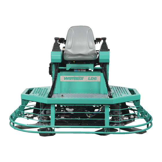
Page 22: Components (Trowel)
COMPONENTS (TROWEL) P/N 45658 Figure 8. LD6 Trowel Components 1. Light, Left Side (Optional) — One of six LED lights 8. Tie-Down Locations (4) — Secure tie-down straps to included with the optional light kit. these attachment points when transporting the trowel. 2. - Page 23 COMPONENTS (TROWEL) P/N 45650 Figure 9. LD6 Trowel Components (Cont.) 15. Seat Switch — Safety feature stops blade rotation 21. Hydraulic Motor (Right Side) — This durable, when the operator leaves the seat. The trowel blades high-torque hydraulic motor rotates the right-side will not rotate unless the operator is seated.
- Page 24 COMPONENTS (TROWEL) Figure 10. LD6 Trowel Components (Cont.) 27. Operator’s Seat — Operator’s seat tilts forward for 33. Fuel Filler Cap — Remove the fuel filler cap to add service access. unleaded gasoline to the fuel tank. Use 87 or 89 octane gasoline only.
-
Page 25: Components (Engine)
COMPONENTS (ENGINE) Figure 11. Vanguard Engine Components 1. Fuel Pump — Delivers gasoline fuel to the engine. 10. Muffler — Reduces noise and emissions. NEVER touch the muffler while the engine is running. 2. Oil Fill Cap — Remove the cap to add fresh engine oil. -
Page 26: Setup
SETUP BATTERY FLOAT PAN INSTALLATION (OPTIONAL) CAUTION Float pans attach to the spider arms and allow early floating on wet concrete and easy movement from wet to dry areas. Use all safety precautions specified by the battery They are also very effective at embedding large aggregates manufacturer when handling the battery. -
Page 27: Inspection
INSPECTION ENGINE OIL Table 6. Recommended Oil Viscosity Grades 1. Make sure the trowel is on a secure, level surface with SAE 30 the engine stopped. 2. Pull the engine oil dipstick (Figure 15) out of its holder SAE 5W-30 and wipe it with a clean cloth. - Page 28 INSPECTION CAUTION DANGER Hydraulic oil can get HOT! Fuel spillage on a hot engine can cause a fire or explosion. If fuel spillage occurs, ALWAYS allow hydraulic oil to cool before wipe up the spilled fuel completely to removing the fill cap. NEVER remove the fill prevent fire hazards.
-
Page 29: Operation
OPERATION The following section is intended to assist the operator with 2. If starting a cold engine, or starting the engine in cold weather, pull the choke knob (Figure 19) outward to operation of the trowel. It is extremely important to read the CLOSED position. - Page 30 OPERATION 4. Insert the ignition key into the ignition switch (Figure 21). 6. Place the engine throttle lever in the FAST (rabbit) While keeping your foot off the foot switch, turn the position. See Figure 22. ignition key clockwise to the START position. Once the engine starts, release the ignition key.
- Page 31 OPERATION STEERING Table 7. Joystick Directional Positioning Two palm-grip joysticks (Figure 23) located to the left and CONTROL JOYSTICK RESULT & DIRECTION right of the operator’s seat provide directional control of the trowel. Causes only the Move LEFT Joystick left side of the FORWARD ride-on trowel to move forward.
- Page 32 OPERATION The rotor speed control lever (Figure 24) controls rotor 3. Push both the left and right joysticks forward speed in conjunction with the foot switch (Figure 25). The (Figure 26). Notice that the trowel begins to move in foot switch rotates the blades while the position of the a forward direction.
- Page 33 OPERATION ENGINE SHUTDOWN 6. Try adjusting the pitch of the blades using the left and right blade pitch control switches (Figure 27). This can 1. Reduce engine speed and allow the engine to idle for be done with the trowel stopped or while the trowel is 3–5 minutes.
-
Page 34: Maintenance
MAINTENANCE Table 8. Maintenance Schedule Periodic Maintenance Interval Check Item Daily Every 25 hours Every 100 hours Every 400 hours Visual check for fluid leaks Check engine oil level Grease trowel arms Change engine oil and filter Service air cleaner pre-cleaner Service air cleaner cartridge After the first 100 hours of operation, Change hydraulic oil filter... - Page 35 MAINTENANCE AIR CLEANER CAUTION The engine air cleaner assembly is equipped with a round Certain maintenance operations or machine adjustments air cleaner cartridge and a foam pre-cleaner. Clean or require specialized knowledge and skill. Attempting to replace the air cleaner elements as necessary. perform maintenance or adjustments without the proper NOTICE knowledge, skills or training could result in equipment...
- Page 36 MAINTENANCE 4. Inspect the pre-cleaner and cartridge. Replace the 2. Pull the engine oil dipstick (Figure 32) out of its holder cartridge if it is excessively dirty. and wipe it with a clean rag. 3. Fully insert the dipstick then remove it again. NOTICE DO NOT use solvents or pressurized air to clean the 4.
- Page 37 MAINTENANCE 4. Remove the oil drain plug (Figure 34) and allow the 8. Coat the seal of the new oil filter (Figure 36) with clean oil to drain into a suitable container through the drain engine oil. Install the new filter by hand until it contacts hole in the engine mounting bracket.
- Page 38 MAINTENANCE HYDRAULIC OIL FILTER 4. Measure the spark plug electrode gap (Figure 37) with a wire-type feeler gauge. If needed, adjust the Change the hydraulic oil filter (Figure 39) after the first gap to 0.030 in. (0.76 mm) by carefully bending the 100 hours of use, then every 250 hours.
- Page 39 MAINTENANCE Draining the Hydraulic Oil TROWEL LUBRICATION CAUTION Regular lubrication is required to maintain your trowel in optimal working condition. Perform the following lubrication Hydraulic oil can get HOT! procedure after every 8 hours of operation. ALWAYS allow hydraulic oil to cool 1.
- Page 40 MAINTENANCE BLADE PITCH ADJUSTMENT 2. Pitch the blades as flat as possible. The adjustment bolts should all barely make contact with the lower wear Perform maintenance adjustment of blade pitch using a plate on the spider. Figure 43 illustrates the correct bolt on the trowel arm lever (Figure 42).
- Page 41 MAINTENANCE SPIDER REMOVAL BLADE REPLACEMENT It is recommended to replace all of the trowel blades at the 1. Remove and set aside the cap plug and retaining screw securing the spider assembly to the hydraulic motor same time. If only one or some of the blades are changed, shaft (Figure 45).
- Page 42 MAINTENANCE TROWEL ARM REMOVAL TROWEL ARM INSPECTION 1. Each trowel arm is held in place at the spider plate Trowel arms can be damaged by rough handling such by a Zerk grease fitting (hex head bolt). Remove the as dropping the trowel on a pad or by striking exposed Zerk grease fitting and the roll pin from the spider plate plumbing, forms or rebar while in operation.
- Page 43 MAINTENANCE Trowel Arm Adjustment 4. Unscrew the locking bolts on the adjustment tool and place the trowel arm into the fixture channel as shown in Figure 49 illustrates a trowel arm adjustment tool. As a Figure 51. A thin shim may be required to cover the blade trowel arm is locked into the adjustment tool, the trowel arm holes on the trowel arm.
- Page 44 MAINTENANCE Reassembly TROWEL DECOMMISSIONING 1. Clean and examine the entire spider assembly including Decommissioning is a controlled process used to safely the upper and lower wear plates and thrust collar. Wire retire a piece of equipment that is no longer serviceable. brush any concrete or rust buildup.
- Page 45 NOTES LD6/LD6SL RIDE-ON POWER TROWEL • OPERATION MANUAL — REV. #6 (02/13/23) — PAGE 45...
-
Page 46: Troubleshooting
TROUBLESHOOTING Trowel Troubleshooting Symptom Possible Problem Solution Other problems? Check seat function with a multimeter. Seat switch not functioning. Loose wire connections? Check wiring. Replace as necessary. Bad contacts? Replace seat cushion (contains the switch). Make certain blades are in good condition, not excessively worn. - Page 47 TROUBLESHOOTING Trowel Troubleshooting (Continued) Symptom Possible Problem Solution Check all electrical connections, including the master Wiring? ON/OFF switch and check to see if wiring is in good condition with no shorts. Replace as necessary. Lights (optional) not working. Check to see if light bulbs are still good. Replace if Lights? broken.
- Page 48 TROUBLESHOOTING Engine Troubleshooting Symptom Possible Problem Solution Spark plug bridging? Check gap, insulation or replace spark plug. Carbon deposit on spark plug? Clean or replace spark plug. Short circuit due to defi cient spark plug Check spark plug insulation, replace if worn. insulation? Improper spark plug gap? Set to proper gap.
-
Page 49: Electrical Component Locator
ELECTRICAL COMPONENT LOCATOR LD6/LD6SL RIDE-ON POWER TROWEL • OPERATION MANUAL — REV. #6 (02/13/23) — PAGE 49... -
Page 50: Electrical Wiring Diagram
ELECTRICAL WIRING DIAGRAM HYDRAULIC COOLER FUSE BLOCK GND KILL RELAY FUSE 1 FUSE 2 FUSE 3 FUSE 4 KEY SWITCH REAR VIEW 16 AWG RED/W +12VDC 10A FUSED 18 AWG RED/B 18 AWG BLACK 18 AWG RED/Y 18 AWG BLACK 18 AWG PINK 14 AWG BLACK ACCESSORY POWER... - Page 51 ELECTRICAL WIRING DIAGRAM LL RELAY IGNITION RELAY COOLER FAN RELAY TYPICAL RELAY AMPLIFIER HYDRAULIC PUMP 16 AWG RED/WHITE 18 AWG RED/BLUE BLACK 18 AWG RED/YELLOW 18 AWG ORANGE/BLUE BLACK 18 AWG BLACK WG BLACK 18 AWG BLACK SPEED LEVER 120Ω 0.4W FOOT SWITCH RESISTOR...
-
Page 52: Electrical Wiring Diagram (Pitch Kit)
ELECTRICAL WIRING DIAGRAM (PITCH KIT) LEFT PITCH SWITCH 12 AWG ORANGE 12 AWG ORANGE 16 AWG RED 16 AWG RED 16 AWG BLACK LEFT PITCH ACTUATOR 14 AWG BLACK RIGHT PITCH SWITCH 12 AWG ORANGE 16 AWG RED 16 AWG RED 16 AWG BLACK 16 AWG BLACK RIGHT PITCH... -
Page 53: Electrical Wiring Diagram (Optional Light Kit)
ELECTRICAL WIRING DIAGRAM (OPTIONAL LIGHT KIT) RIGHT FRONT LIGHT LIGHT SWITCH 18 AWG RED/WHITE 18 AWG BLACK RIGHT SIDE LIGHT 18 AWG RED/WHITE 18 AWG BLACK RIGHT REAR LIGHT 18 AWG RED/WHITE 18 AWG BLACK LEFT FRONT LIGHT 14 AWG RED/WHITE 14 AWG BLACK 18 AWG RED/WHITE 18 AWG BLACK... -
Page 54: Electrical Wiring Diagram (Optional Spray Kit)
ELECTRICAL WIRING DIAGRAM (OPTIONAL SPRAY KIT) SPRAY PUMP RH SPRAY SWITCH LH SPRAY SWITCH +12 VDC +12 VDC 18 AWG RED/WHITE 18 AWG BLACK CONNECT TO PITCH KIT HARNESS OR LIGHT KIT HARNESS ACCESSORY POWER PAGE 54 — LD6/LD6SL RIDE-ON POWER TROWEL • OPERATION MANUAL — REV. #6 (02/13/23) -
Page 55: Electrical Wiring Diagram (Power And Ground)
ELECTRICAL WIRING DIAGRAM (POWER AND GROUND) GND KILL RELAY KEY SWITCH REAR VIEW STARTER BLACK 18 AWG TO GROUND SOLENOID BLACK 18 AWG START TO HARNESS PINK 18 AWG SPLICE BLACK/YELLOW 18 AWG SPARK PLUG UNIT LT. BLUE/PINK 18 AWG IGNITION CHASSIS GROUND... -
Page 56: Hydraulic Component Locator
HYDRAULIC COMPONENT LOCATOR PAGE 56 — LD6/LD6SL RIDE-ON POWER TROWEL • OPERATION MANUAL — REV. #6 (02/13/23) -
Page 57: Hydraulic System Diagram
HYDRAULIC SYSTEM DIAGRAM CYCLONE RESERVOIR (PORT A) HYDRAULIC HYDRAULIC TANK FILTER HIGH PRESSURE LINES (5,100 PSI) MID PRESSURE LINES (2,500 PSI) LOW PRESSURE LINES (<250 PSI) RETURN LINES (TANK) CASE DRAIN LINES (<35 PSI) RIGHT-HAND SUCTION LINE STEERING CONNECTION MADE BY FITTING VALVE RIGHT HYDRAULIC... - Page 58 © COPYRIGHT 2023, MULTIQUIP INC. Multiquip Inc , the MQ logo are registered trademarks of Multiquip Inc. and may not be used, reproduced, or altered without written permission. All other trademarks are the property of their respective owners and used with permission.
Need help?
Do you have a question about the Whiteman LD6SL and is the answer not in the manual?
Questions and answers