
Related Manuals for GIGAMEDIA GGM GS08PLUS


Summary of Contents for GIGAMEDIA GGM GS08PLUS
- Page 1 User Manual GGM GS08PLUS 8-Port PoE 10/100/1000Mbps with 2-Port Gigabit SFP Web Managed Switch...
-
Page 2: Table Of Contents
Content Content…………………………………………………………………………………I Introduction…………………………………………………………………………….. Product Overview……………………………………………………………………………….3 Web Management Feature…………………………………………………………………….3 Specification……………………………………………………………………………………..4 Mechanical……………………………………………………………………………………..4 Performance…………………………………………………………………………………..5 Package Contents……………………………………………………………………………...5 Hardware Description………………………………………………………………….6 Physical Dimensions / Weight………………………………………………………………...6 Front Panel……………………………………………………………………………………...6 LED Indicators…………………………………………………………………………………..6 Rear Panel………………………………………………………………………………………7 Hardware Installation…………………………………………………………………………..7 Software Description…………………………………………………………………..8 Login……………………………………………………………………………………………..8 Configuration……………………………………………………………………………………9 System ..…………………………………………………………………….……………..9 System Configuration……………………………………………...…………………...9 Ports ………….…………………………………………………..…………………………..11 Port Configuration ……………………...……………….…………………………..11 Vlan…………………………………….……………………….…………………………...12 Port Segmentation (VLAN) Configuration……………….……………………..13 Add a Vlan………………………………………………….……………...……………13... - Page 3 IGMP Snopping…………………………………………………………………………. 19 IGMP Configuration…………………………………………………………………19 Mirrioring…………………………………………………………………………………2 0 Moirrioring Configuration………………………………………………………… ...20 QoS……………………………………………………………………………………….21 QoS Configuration…………………………………………………………………..22 QoS Mode: QoS Disabled………………………………………………………….22 QoS Mode: 802.1p…………………………………………………………………..22 QoS Mode: DSCP…………………………………………………………………...23 Power over Ethernet………………………………………………………………………..24 PoE Configuration……………………………………………………………… ..25 Storm Control……………………………………………………………………………25 Storm Control Configuration……………………………………………………….25 Monitoring…………………………………………………………………………………...26 Statistic Overview……………………………………………………………………… 26 Detailed Statistic………………………………………………………………………..27 LACP Status…………………………………………………………………………….
-
Page 4: Introduction
Introduction Product Overview This switch is a Web Smart Switch equipped with 8-ports PoE 10/100/1000BaseT(X) plus 2-port gigabit SFP. It is designed for easy installation and high performance in an environment where traffic is on the network and the number of users increased continuously. The compact rigid 19”... -
Page 5: Specification
IGMP Status VeriPHY Ping Maintenance Warm Restart Factory Default Software Upload Configuration File Transfer Logout Specifications Standard IEEE 802.3 10BaseT IEEE 802.3u 100BaseTX IEEE 802.3ab 1000BaseT IEEE 802.3af PoE IEEE 802.3at PoE IEEE 802.3z 1000BaseSX/LX IEEE 802.3x Full-duplex Flow Control IEEE 802.3ad Link Aggregation IEEE 802.1Q VLAN IEEE 802.1d Spanning tree protocol... -
Page 6: Performance
Performance MAC Address & Multicast group: 8K Buffer Memory: 176 KB Jumbo Frames: 9.6K Transmission Method: Store and Forward Package Contents Before you start to install this switch, please verify your package that contains the following items: ... -
Page 7: Physical Dimensions/ Weight
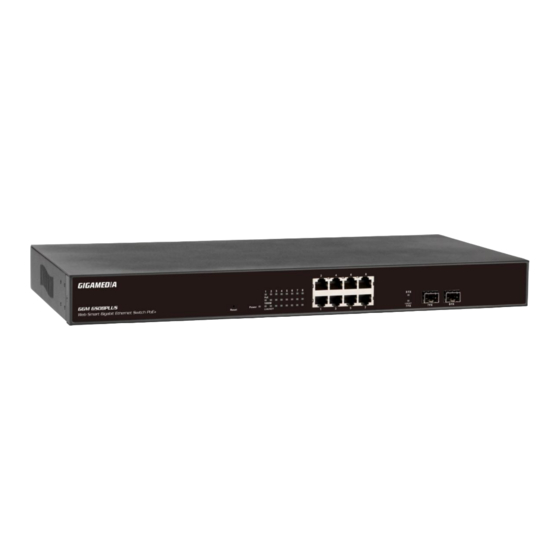
Physical Dimensions/ Weight 440 × 220 × 44 mm (L x D x H ) / 3.2kg Front Panel The front Panel of the Web Smart Switch consists of 8 gigabit RJ-45 ports+2 gigabit SFP open slot. The LED Indicators are also located on the front panel. LED Display RJ-45 Port SFP Open Slot... -
Page 8: Hardware Installation
Hardware Installation Set the switch on a large flat space with a power socket close by. The flat space should be clean, smooth, level and sturdy. Make sure there is enough clearance around the switch to allow attachment of cables, power cord and allow air circulation. - Page 9 Figure 1-1 After the user login, the right side of website shows all functions as Fig. 1-2. Figure 1-2...
-
Page 10: Configuration
Configuration System System Configuration This page shows system configuration information. User can configure lots of information as Fig. 1-3: Figure 1-3 MAC Address: Displays the unique hardware address assigned by manufacturer (default). S/W Version: Displays the switch’s firmware version. ... -
Page 11: Ports
DHCP Enabled: Click the box to enable DHCP Fallback IP address: Manually assign the IP address that the network is using. The default IP is 192.168.2.1 Fallback Subnet Mask: Assign the subnet mask to the IP address ... - Page 12 Power Saving Mode Adjusts the power provided to ports based on the length of the cable used to connect to other devices. Only sufficient power is used to maintain connection requirements. Mode: allow user to manually set the port speed such as Auto, 10 half, 10 Full, 100 Half, 100 Full, 1000 Full or Disabled.
-
Page 13: Vlan
VLAN A Virtual LAN (VLAN) is a logical network grouping that limits the broadcast domain, which would allow you to isolate network traffic, so only the members of the same VLAN will receive traffic from the ones of the same VLAN. Basically, creating a VLAN from a switch is logically equivalent of reconnecting a group of network devices to another Layer 2 switch. -
Page 14: Vlan Per Port Configuration
Figure 1-5-2 VLAN Per Port Configuration The 802.1Q Per Port Configuration page allows you to change the VLAN parameters for individual ports or trunks. You can configure VLAN behavior for specific interfaces, including the accepted frame types and default VLAN identifier (PVID). -
Page 15: Aggregation
Disabled) Packet Type: Sets the interface to accept all frame types, including tagged or untagged frames, or only tagged frames. (Default: All) If the Packet Type is set to “All,” the port can accept incoming tagged and untagged packets. Any received packets that are untagged are assigned to the default VLAN. -
Page 16: Lacp
Figure 1-6 LACP IEEE 802.3ad Link Aggregation Control Protocol (LACP) increases bandwidth by automatically aggregating several physical links together as a logical trunk and providing load balancing and fault tolerance for uplink connections. LACP Port Configuration Port: The port number. ... -
Page 17: Rstp
RSTP IEEE 802.1w Rapid Spanning tree protocol (LACP) provides a loop-free network and redundant links to the core network with rapid convergence to ensure faster recovery from failed links, enhancing overall network stability and reliability. RSTP System Configuration System Priority: This parameter configures the spanning tree priority globally for this switch. - Page 18 Path Cost: This parameter is used by the STP to determine the best path between devices. Therefore, lower values should be assigned to ports attached to faster media, and higher values assigned to ports with slower media. Set the RSTP pathcost on the port. Number between 0 - 200000000. 0 means auto generated pathcost.
- Page 19 Figure 1-8-2 Figure 1-8-3 Figure 1-8-4...
-
Page 20: Igmp Snopping
IGMP Snooping IGMP Snooping is the process of listening to IGMP network traffic. IGMP Snooping, as implied by the name, is a feature that allows a layer 2 switch to “listen in” on the IGMP conversation between hosts and routers by processing the layer3 IGMP packets sent in a multicast network. -
Page 21: Moirrioring Configuration
Mirroring Port Mirroring is used on a network switch to send a copy of network packets seen on one switch port (or an entire VLAN) to a network monitoring connection on another switch port. This is commonly used for network appliances that require monitoring of network traffic, such as an intrusion-detection system. -
Page 22: Qos
Figure 1-10-2 Quality of Service (QoS) In QoS Mode, select QoS Disabled, 802.1p, or DSCP to configure the related parameters. QoS Configuration Strict: Services the egress queues in sequential order, transmitting all traffic in the higher priority queues before servicing lower priority queues. ... -
Page 23: Qos Mode: Qos Disabled
Figure 1-11-1 QoS Mode: QoS Disabled When the QoS Mode is set to QoS Disabled, the following table is displayed. Figure 1-11-2 QoS Mode: 802.1p Packets are prioritized using the 802.1p field in the VLAN tag. This field is three bits long, representing the values 0 - 7. When the QoS Mode is set to 802.1p, the 802.1p Configuration table appears, allowing you to map each of the eight 802.1p values to a local priority queue (low, normal, medium or high). -
Page 24: Qos Mode: Dscp
Figure 1-11-3 Figure 1-11-4 QoS Mode: DSCP DSCP: Packets are prioritized using the DSCP (Differentiated Services Code Point) value. The Differentiated Services Code Point (DSCP) is a six-bit field that is contained within an IP (TCP or UDP) header. The six bits allow the DSCP field to take any value in the range 0 - 63. -
Page 25: Power Over Ethernet
DSCP Configuration table to a common priority queue. Use Custom if you want to set each value individually. When the QoS Mode is set to DSCP, the DSCP Configuration table is displayed as shown below. Figure 1-11-5 Figure 1-11-6 PoE (Power over Ethernet) Configuration Power over Ethernet (PoE) is an advanced technology providing a whole new application aspect for networking products. -
Page 26: Poe Configuration
PoE Configuration Remote access and monitor the attached PD (Powered Device) status by using Enable/Disable function. PoE Enabled: POE of the port is able to supply power to the attached PD (Powered Device) PD Class: Detect the class of PD ... -
Page 27: Monitoring
Figure 1-13-1 Enable Rate Limit: Click the check box to enable storm control. Rate (number of frames per second): The Rate field is set by a single drop-down list. The same threshold is applied to every port on the switch. When the threshold is exceeded, packets are dropped, irrespective of the flow-control settings. -
Page 28: Lacp Status
Figure 2-1 Detailed Statics Figure 2-2 LACP Status LACP Aggregation Overview Figure 2-3-1 Port: The port number. Port Active: Shows if the port is a member of an active LACP group. Partner Port Number: A list of the ports attached at the remote end of this LAG link member. -
Page 29: Lacp Port Status
LACP Port Status Figure 2-3-2 RSTP Status RSTP VLAN Bridge Overview Figure 2-4-1 Hello Time: Interval (in seconds) at which the root device transmits a configuration message. Max Age: The maximum time (in seconds) a device can wait without receiving a configuration message before attempting to reconfigure. -
Page 30: Rstp Port Status
Topology: Indicates if spanning tree topology is steady or undergoing reconfiguration. (The time required for reconfiguration is extremely short, so no values other that “steady” state are likely to be seen in this field.) Root ID : The priority and MAC address of the device in the Spanning Tree that this switch has accepted as the root device, and the port connected to the root device. -
Page 31: Veriphy
VLAN ID: VLAN ID number. Querier: Show whether Querying is enabled. Queries transmitted: Show the number of transmitted Query packets. Queries received: Show the number of received Query packets. v1 Reports: Show the number of received v1 Report packets. ... -
Page 32: Ping
Figure 2-6-2 Figure 2-6-3 Figure 2-6-4 Ping This command sends ICMP echo request packets to another node on the network. -
Page 33: Ping Parameters
Ping Parameters Target IP Address: IP address of the host Count: Number of packets to send. (Range: 1-20) Time Out: setting the time period of host will be Ping Use the ping command to see if another site on the network can be reached. The following are some results of the ping command: ... - Page 34 Figure 2-7-2...
-
Page 35: Maintenance
Figure 2-7-3 Maintenance Warm Restart Press Yes button to restart the switch, the reset will be complete when the power lights stop blinking. Figure3-1 Factory Default This function is to force the switch back to the original factory settings. To reset the switch, select “Reset to Factory Defaults”... -
Page 36: Software Upload
Software upload Select “Upgrade Firmware” from the Tools drop-down list then click on the “Browse” button to select the firmware file. Click the APPLY button to upgrade the selected switch firmware file. User can download firmware files for user’s switch from the Support section of your local supplier. Figure 3-3 Configuration File Transfer Configuration file transfer allows you to save the switch’s current configuration... - Page 37 Figure 3-5 Reset button for the factory default setting Please take the following steps to reset the Web Smart Switch back to the original default: Step 1: Turn on the Web Smart Switch Step 2: Press and hold the reset button continuously for 5 seconds and release the reset button.
Need help?
Do you have a question about the GGM GS08PLUS and is the answer not in the manual?
Questions and answers