
Related Manuals for GIGAMEDIA GGM FES08P2G


Summary of Contents for GIGAMEDIA GGM FES08P2G
- Page 1 User Manual GGM FES08P2G 8-port 10/100M PoE + 1 Gigabit Copper & SFP Port Ethernet Switch...
- Page 2 FCC Warning This Equipment has been tested and found to comply with the limits for a Class-A digital device, pursuant to Part 15 of the FCC rules. These limits are designed to provide reasonable protection against harmful interference in a residential installation. This equipment generates, uses, and can radiate radio frequency energy.
-
Page 3: Table Of Contents
Table of Contents Before Starting..........................5 Intended Readers ........................6 Icons for Note, Caution, and Warning ................... 6 Product Package Contents ..................... 7 Chapter 1: Product Overview ....................8 1.1. Product Brief Description ....................9 1.2. Product Specification .....................10 1.3. Hardware Description .....................12 1.4. - Page 4 3.6. Web Management - Security...................38 3.6.1. Security - MAC Address Binding ................38 3.6.2. Security - TCP/UDP Filter ..................39 3.7. Web Management - Spanning Tree ................40 3.7.1. Spanning Tree - STP Bridge Settings ..............40 3.7.2. Spanning Tree - STP Port Settings ................41 3.7.3.
-
Page 5: Before Starting
Before Starting In Before Starting: This section contains introductory information, which includes: Intended Readers Icons for Note, Caution, and Warning Product Package Contents... -
Page 6: Intended Readers
Intended Readers This manual provides information regarding to all the aspects and functions needed to install, configure, use, and maintain the product you’ve purchased. This manual is intended for technicians who are familiar with in-depth concepts of networking management and terminologies. Icons for Note, Caution, and Warning To install, configure, use, and maintain this product properly, please pay attention when you see these icons in this manual:... -
Page 7: Product Package Contents
Product Package Contents Before starting install this product, please check and verify the contents of the product package, which should include the following items: One Network Switch One Power Cord One User Manual CD One pair Rack-mount kit + 8 Screws Note: If any item listed in this table above is missing or damaged, please contact your distributor or retailer as soon as possible. -
Page 8: Chapter 1: Product Overview
Chapter 1: Product Overview In Product Overview: This section will give you an overview of this product, including its feature functions and hardware/software specifications. Product Brief Description Product Specification Hardware Description Hardware Installation... -
Page 9: Product Brief Description
1.1. Product Brief Description Introduction This switch is 8-port 10M/100M + 2 port Giga uplink (1*TP+1*SFP) Desktop Web Smart PoE Switch, the switch supports IEEE 802.3at Power over Ethernet standard, maximum 130W power consumption per system and no special network cable required for your PD devices. The switch also provides exceptionally smart Web management features, such as VLAN, QoS, RSTP, LACP, Port Security…etc. -
Page 10: Product Specification
1.2. Product Specification Interface 10/100 Base RJ45 Ports Gigabit RJ45 Port Gigabit SFP Port System Performance Packet Buffer 2.75Mb MAC Address Table Size Switching Capacity 5.6Gbps Forwarding Rate 4.17Mpps PoE Features IEEE 802.3 af/at IEEE 802.3 af/at Number of PSE Ports Max. - Page 11 Mechanical Power Input 100~240VAC Dimension (H*W*D) 44 × 266 × 160 mm Power, Link/Act, PoE, 1000M Operating Temperature 0 ~ 45°C Storage Temperature -20 ~ 90°C 10~90% (non-condensing) Operating Humidity Weight 1.8 KG Certification CE, FCC Class B Standard IEEE 802.3 – 10BaseT ...
-
Page 12: Hardware Description
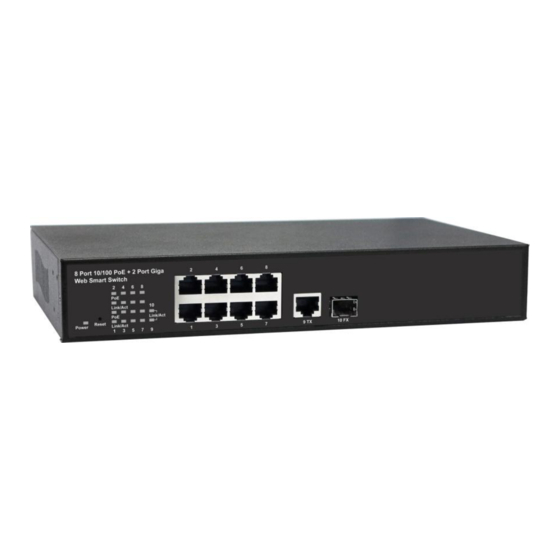
1.3. Hardware Description This section mainly describes the hardware of this PoE switch and gives a physical and functional overview on the certain switch. Front Panel The front panel of this switch consists of 16 10/100 Base-TX RJ-45 ports, 1 Gigabit SFP/RJ45 port. -
Page 13: Hardware Installation
1.4. Hardware Installation To install this switch, please place it on a large flat surface with a power socket close by. This surface should be clean, smooth, and level. Also, please make sure that there is enough space around this switch for RJ45 cable, power cord and ventilation. If you’re installing this switch on a 19-inch rack, please make sure to use the rack-mount kit (L brackets) and screws come with the product package. -
Page 14: Chapter 2: Preparing For Management
Chapter 2: Preparing for Management In Preparing for Management: This section will guide your how to manage this product via management web page. Preparation for Web Interface... -
Page 15: Preparation For Web Interface
2.1. Preparation for Web Interface The management web page allows you to use a web browser (such as Microsoft IE, Google Chrome, or Mozilla Firefox) to configure and monitor the switch from anywhere on the network. Before using the web interface to manage your switch, please verify that your switch and your PC are on the same network. - Page 16 The web browser will prompt you to log in. The default username/password for the configuration web page is admin/admin. For more information, please refer to Appendix B: IP Configuration for Your PC.
-
Page 17: Chapter 3: Web Management
Chapter 3: Web Management In Web Management: As mentioned in Chapter 2.1. Preparation for Web Interface, This switch provides a web-based management interface. You can make all settings and monitor system status with this management web page. Configuration/Monitor options included in the management web page can be divided into the following 3 categories, which will be discussed in detail in this chapter: ... -
Page 18: Web Management - Overview
3.1. Web Management - Overview This switch has a management web page that allows the user to make configurations and view system status. The configuration options are divided into the following categories. Administrator: This section contains settings regarding to the switch’s system, including system password, switch IP settings, system status, updating firmware, system reboot and reset all settings back to factory default. -
Page 19: Web Management - Administrator
3.2. Web Management - Administrator 3.2.1. Administrator - Authentication Configuration Here you can set the username and password for the switch administrator. Please note that the username and password must be alphanumeric characters, underline (“_”), dash (“-”), plus sign (“+”), and equal sign (“=”). Username Input the username for the switch administrator here in this field. -
Page 20: Administrator - System Ip Configuration
3.2.2. Administrator - System IP Configuration This web page allows you to set the switch’s IP address, subnet mask and gateway. Also, you can enable the switch’s DHCP client function here as well. IP Address Input the IP address of the switch here in this field. The switch’s default IP address is 192.168.2.1. -
Page 21: Administrator - System Status
3.2.3. Administrator - System Status MAC Address This field displays the switch’s MAC address. Number of Ports This field displays the switch’s number of ports. Comment Here you can input the comment for the switch. Note: The comment must be alphanumeric characters, underline (“_”), dash (“-”) and plus sign (“+”). -
Page 22: Administrator - Load Default Setting
3.2.4. Administrator - Load Default Setting Here you can reset the settings of the switch back to the factory default value. Please note that the IP settings (IP address, subnet mask and gateway) and system username/password won’t be reset back to the factory default value. Button ... -
Page 23: Administrator - Firmware Update
3.2.5. Administrator - Firmware Update Here you can update new firmware to the switch. Please note that before updating the firmware, the system will erase the current firmware. Therefore, please make sure that you have the right firmware available in your PC before firmware updating. Password/Reconfirm For security reasons, you have to enter the system’s password here in these two fields before updating new firmware. -
Page 24: Web Management - Port Management
3.3. Web Management - Port Management 3.3.1. Port Management - Port Configuration This page allows you to configure port settings such as speed, duplex, pause, and backpressure. Also, you can view all the ports’ settings here on this web page as well. TX/RX Capability This option allows you to enable/disable the data transmitting/receiving function. -
Page 25: Port Management - Port Mirroring
3.3.2. Port Management - Port Mirroring he Port Mirroring function allows you to monitoring network traffic of the source ports (ports under monitoring) from designated destination ports (which duplicated packets from source ports will be sent to). Dest. Port Here you can set ports which duplicated packets from source ports will be sent to. Monitored Packets This scroll-down menu allows you to set which packets will be duplicated and sent to the destination ports:... -
Page 26: Port Management - Bandwidth Control
3.3.3. Port Management - Bandwidth Control This page allows the setting of the bandwidth for each port. Port NO. This field allows you to select the ports that will apply the settings you’ve made here. Tx/Rx Rate Here you can set the bandwidth rate of Tx (transmitting) and Rx (receiving). The bandwidth rate can be a number from 0 to 255, where 0 is full speed. -
Page 27: Port Management - Broadcast Storm Control
3.3.4. Port Management - Broadcast Storm Control Broadcast storms may occur when a device on your network is malfunctioning, or if application programs are not well designed or properly configured. If there is too much broadcast traffic on your network, performance can be severely degraded or everything can come to complete halt. -
Page 28: Port Management - Poe
3.3.5. Port Management - PoE Here you can enable/disable the PoE function on each port, or view each port’s PoE status. Enable Enable/disable the PoE function on a certain port. Button Update: Apply all the settings you’ve made here. -
Page 29: Web Management - Vlan Setting
3.4. Web Management - VLAN Setting VLAN stands for Virtual LAN, which is a logical network grouping that limits the broadcast domain and allows you to isolate network traffic so that only the members of the same VLAN group can communicate with each other. This switch supports two different types of VLAN: port-based VLAN and tag-based VLAN. - Page 30 VLAN Mode - Tag-based VLAN VLAN Mode Change VLAN Mode: Press this button to change the VLAN mode from tag-based VLAN to port-based VLAN. Please note that all the VLAN settings will be reset to default and lost if you change the VLAN mode. Tag Mode Here you can set each port’s VLAN tag mode.
-
Page 31: Vlan Setting - Vlan Member
3.4.2. VLAN Setting - VLAN Member VLAN Member - Port-based VLAN Port-based VLAN supports 26 VLAN groups. You can assign ports to a certain VLAN group here in this management web page. Port This scroll-down menu allows you to select the port that you would like to configure. After choosing the port, please press the Read button located at the right side to load the selected port’s port-based VLAN setting. - Page 32 VLAN Member - Tag-based VLAN Here you can define and configure your VLAN groups, assign the VLAN ID, select the VLAN member ports, assign the PVID and check the configuration result. VID (VLAN ID) Here you can add a VLAN group with the set VNAL ID. Button ...
-
Page 33: Vlan Setting - Multi To 1 Setting
3.4.3. VLAN Setting - Multi to 1 Setting Here you can set the multi to 1 VLAN. If you apply this VLAN setting, all port-based VLAN or tag-based VLAN set previously will be replaced by the settings you’ve made here. The multi to 1 VLAN is port-based VLAN only. -
Page 34: Web Management - Per Port Counter
3.4. Web Management - Per Port Counter 3.4.1. Per Port Counter - Port Counter Here you can view the transmitting/receiving packet counters. Counter Mode Selection This scroll-down menu allows you to view Transmit Packet & Receive Packet, Collision Count & Transmit Packet, Drop Packet & Receive Packet, and CRC Error Packet & Receive Packet. Button ... -
Page 35: Web Management - Qos Setting
3.5. Web Management - QoS Setting Here you can configure QoS policy priority mode and CoS (Class of Service). QoS (Quality of Service) refers to mechanisms in the network software that make the actual determination of which packets have the priority. CoS refers to feature sets, or groups of services, that are assigned to users based on company policy. -
Page 36: Qos Setting - Port, 802.1P, Ip/Ds Based
3.5.2. QoS Setting - Port, 802.1p, IP/DS Based This page allows you to enable Port Based, VLAN Tag or IP/DS mode of COS. Port Base Set the port priority to high, other ports that are not selected here will be set to low priority. A packet received by a high priority port is handled as a high priority packet. -
Page 37: Qos Setting - Tcp/Udp Port Based
3.5.3. QoS Setting - TCP/UDP Port Based This page allows you to define the Option type of the pre-defined protocols or user-defined protocols. Option The Class of Service for TCP/UDP port number allows the network administrator to assign the specific application to a priority queue. ... -
Page 38: Web Management - Security
3.6. Web Management - Security 3.6.1. Security - MAC Address Binding The feature allows you to bind 3 MAC addresses to one physical port. After binding MAC addresses to a port, only the network devices with the binding MAC addresses can access to that port. -
Page 39: Security - Tcp/Udp Filter
3.6.2. Security - TCP/UDP Filter This page allows user to configure the TCP/DUP limit. Function Enable This scroll-down menu allows you to enable/disable TCP/UDP filter function. Port Filtering Rule The outgoing packet with selected protocol will be either forwarded or dropped at secure WAN port. -
Page 40: Web Management - Spanning Tree
3.7. Web Management - Spanning Tree 3.7.1. Spanning Tree - STP Bridge Settings STP Mode This scroll-down menu allows you to set the STP mode: Disable: Disable the STP function. STP: Set the STP mode to Spanning Tree Protocol. ... -
Page 41: Spanning Tree - Stp Port Settings
3.7.2. Spanning Tree - STP Port Settings The STP Port Setting page allows you to change the port priority and its path cost. When STP or RSTP is enabled, the system automatically assigns the port priority and path cost to the port. Also, this page displays the STP Port Status. -
Page 42: Spanning Tree - Loopback Detection
3.7.3. Spanning Tree - Loopback Detection Loopback Detection Function This column allows you to enable or disable Loopback Detection function. Auto Wake Up When the system detects a loopback occurs in the network, the system will shut down the ports that cause network loopback. The ports that were shut down will be re-activated after the time set in the Auto Wake Up field passed if this function is enabled. -
Page 43: Web Management - Trunking
3.8. Web Management - Trunking 3.8.1. Trunking - Link Aggregation Settings Port trunk allows multiple links to be bundled together and act as a single physical link for increased throughput. It provides load balancing, and redundancy of links in a switched inter-network. - Page 44 Operation Key You can input the operation key here in this field. Time Out You can set the value of the aggregation time out here. The scroll-down menu contains two options: Long Time Out: 30 seconds Short Time Out: 3 seconds Activity This scroll-down menu allows you to set the LACP role for the aggregation group: ...
-
Page 45: Web Management - Backup/Recovery
3.9. Web Management - Backup/Recovery You can download or upload system settings here. Button Download: Press this button to save all the current settings as “*.bin” file. Choose File: Press this button to choose a pre-saved configuration file that will be uploaded to the switch. -
Page 46: Web Management - Miscellaneous
3.10. Web Management - Miscellaneous Output Queue Aging Time This function is used to avoid the traffic jam that happens on one port won’t cause the congestion of other ports. In some application, for example the IPTV Multicast communication, the multicast stream is continuously generating from the source port, the client port may be congested because of the limited bandwidth or slow network processing ability. - Page 47 IGMP Snooping V1 & V2 A switch will, by default, flood multicast traffic to all ports in a broadcast domain. Multicast can cause unnecessary load on host devices by requiring them to process packets they have not solicited. The IGMP snooping is a feature that allows the switch to listen in on the IGMP conversation between hosts and routers.
-
Page 48: Web Management - Logout
3.11. Web Management - Logout Button Accept: Logout the management web page. Back: Cancel and go back to the management web page. - Page 49 Revision History...
Need help?
Do you have a question about the GGM FES08P2G and is the answer not in the manual?
Questions and answers