Advertisement
Trennschaltverstärker
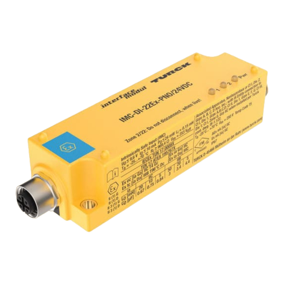
IMC-DI-22Ex-PNO/24VDC
IMC-DI-22Ex-PNC/24VDC
Gerätekurzbeschreibung
• Zweikanaliger Trennschaltverstärker
• Galvanisch getrennte Übertragung von
binären Schaltzuständen
• Eigensichere Eingangskreise Ex ia zum
Anschluss von Sensoren nach EN 60947-5-6
(NAMUR) oder mechanischen Schaltern, die
sich im Ex-Bereich befinden dürfen
• Anwendungsbereich nach ATEX:
II (1) GD, II 3 GD
• Zugelassen für Einbau in Zone 2 und 22
• Schutzart IP67 mit aufgeschraubten Steck-
verbindern
• Galvanische Trennung von Eingangskreis
zu Ausgangskreis
• Überwachung der Eingangskreise auf
Drahtbruch und Kurzschluss
• Zwei Transistorausgänge
– IMC-DI-22Ex-PNO: Schließer
– IMC-DI-22Ex-PNC: Öffner
LED-Anzeigen (Fig. 1 + 2)
Pwr grün Betriebsbereitschaft
1, 2 gelb Transistor leitend
aus
Transistor gesperrt
rot
Fehler im Eingangskreis,
Transistor gesperrt
Pinbelegung (Fig. 2)
Ex-Anschluss
1, 4 Eigensicherer Eingangskreis Kanal 1
2, 3 Eigensicherer Eingangskreis Kanal 2
Nicht-Ex-Anschluss
1, 3 Betriebsspannungsanschluss
4, 3 Transistorausgang Kanal 1
2, 3 Transistorausgang Kanal 2
Anschluss durch M12 x 1-Steckverbinder
Fig. 1
Isolation switching amplifier
IMC-DI-22Ex-PNO/24VDC
IMC-DI-22Ex-PNC/24VDC
Short description
•
Dual channel isolating switching amplifier
•
Galvanically isolated transmission of binary
switching signals
•
Intrinsically safe input circuits Ex ia for sensors
according to EN 60947-5-6 (NAMUR) or
mechanical switches, which may be located in
hazardeous areas
•
Area of application according to ATEX:
II (1) GD, II 3 GD
•
Approved for installation in zone 2 and 22
•
Protection degree IP67 with screwed
connectors
•
Galvanic isolation between input and
output circuit
•
Input circuit monitoring for wire-break and
short-circuit
•
Two transistor outputs:
– IMC-DI-22Ex-PNO: N.O.
– IMC-DI-22Ex-PNC: N.C.
LED indications (Fig. 1 + 2)
Pwr green Power on
1, 2 yellow Transistor conducting
off
Transistor inhibited
red
Input circuit error,
transistor inhibited
Pin configuration (Fig. 2)
Ex-connection
1, 4 Intrinsically safe input circuit channel 1
2, 3 Intrinsically safe input circuit channel 2
Non-Ex-connection
1, 3 Supply voltage connection
4, 3 Transistor output channel 1
2, 3 Transistor output channel 2
Connection with M12 x 1 connectors
Fig. 2
1
NAMUR
2
NAMUR
2
ç
1
3
4
1
NAMUR
2
NAMUR
Amplificateur séparateur
IMC-DI-22Ex-PNO/24VDC
IMC-DI-22Ex-PNC/24VDC
Description brève
•
Amplificateur séparateur à deux canaux
•
Transmission des états de commutation
binaires séparée galvaniquement
•
Circuits d'entrée à sécurité intrinsèque Ex ia
pour le raccordement de détecteurs suivant
EN 60947-5-6 (NAMUR) ou de commutateurs
mécaniques pouvant se trouver dans la zone
Ex
•
Plage d'applicat. suivant ATEX: II (1) GD, II 3 GD
•
Certifié pour montage en zone 2 et 22
•
Mode de protection IP67 avec connecteurs
vissés
•
Séparation galvanique du circuit d'entrée par
rapport au circuit de sortie
•
Surveillance du circuit d'entrée aux ruptures
de câble et courts-circuits
•
Deux sorties de transistor
– IMC-DI-22Ex-PNO: N.O.
– IMC-DI-22Ex-PNC: N.C.
Visualisations par LED (Fig. 1 + 2)
Pwr verte Tension de service
1, 2
jaune Transistor passant
off
Transistor bloqué
rouge Défaut dans le circuit
d'entrée, transistor bloqué
Configuration des broches (Fig. 2)
Connexion Ex
1, 4
Circ. d'entrée à sécurité intrins. canal 1
2, 3
Circ. d'entrée à sécurité intrins. canal 2
Connexion non Ex
1, 3
Raccordement de la tension de service
4, 3
Sortie de transistor canal 1
2, 3
Sortie de transistor canal 2
Connexion par connecteur M12 x 1
IMC-DI-22Ex-PNO/24VDC
BN
+ 1
1
Pwr
BU
YE/RD
– 4
GN
2
BN
YE/RD
+ 2
BU
– 3
IMC-DI-22Ex-PNC/24VDC
BN
+ 1
1
Pwr
BU
YE/RD
– 4
GN
2
BN
YE/RD
+ 2
BU
– 3
1 +
24 VDC
3 –
2
2
100 mA
4
1
2
è
3
1
4
1 +
24 VDC
3 –
2
2
100 mA
4
1
Advertisement
Table of Contents

Related Manuals for turck IMC-DI-22Ex-PNO/24VDC


Summary of Contents for turck IMC-DI-22Ex-PNO/24VDC
- Page 1 Trennschaltverstärker Amplificateur séparateur Isolation switching amplifier IMC-DI-22Ex-PNO/24VDC IMC-DI-22Ex-PNO/24VDC IMC-DI-22Ex-PNO/24VDC IMC-DI-22Ex-PNC/24VDC IMC-DI-22Ex-PNC/24VDC IMC-DI-22Ex-PNC/24VDC Gerätekurzbeschreibung Short description Description brève • Zweikanaliger Trennschaltverstärker • • Dual channel isolating switching amplifier Amplificateur séparateur à deux canaux • Galvanisch getrennte Übertragung von • • Galvanically isolated transmission of binary Transmission des états de commutation...
- Page 2 Steckverbinder und des Gehäuses geschützt wer- the housing with the TURCK metal cover plate recouvrement métallique de TURCK, type IMC-SG den. Die Abdeckplatte IMC-SG muss mit den mit- IMC-SG (Ident no.: 7560016).
- Page 3 All valid national and international sont au courant des prescriptions nationales et internatio- len Vorschriften über den Ex-Schutz durchgeführt werden. approvals covering Turck devices are obtainable via the nales sur la protection Ex concernées. Internet (www.turck.com). The special conditions of IECEx Les données essentielles de l‘attestation d‘examen CE...
- Page 4 Irrtümer und Änderungen vorbehalten / Subject to change without notice / Sous réserve de modifications • © Hans Turck GmbH & Co. KG 2012 Hans Turck GmbH & Co. KG • Witzlebenstraße 7 • 45472 Mülheim/Ruhr • Germany • Tel. +49 (0) 208/4952-0 • Fax +49 (0) 208/4952-264 • more@turck.com • www.turck.com...
Need help?
Do you have a question about the IMC-DI-22Ex-PNO/24VDC and is the answer not in the manual?
Questions and answers