Advertisement
Quick Links
Trennschaltverstärker
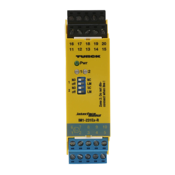
IM1-231Ex-R
Gerätekurzbeschreibung
• Galvanisch getrennte Übertragung von
binären Schaltzuständen
• Zweikanalig, mit Störmeldeausgang
• Eigensichere Eingangskreise Ex ia
• Anwendungsbereich nach ATEX:
II (1) GD, II 3 G
• Zugelassen für Einbau in Zone 2
• Anschluss von Sensoren nach
EN 60947-5-6 (NAMUR) oder
mechanischen Schaltern
• Kanalweise einstellbare Wirkungsrichtung
• Kanalweise aktivierbare Eingangskreis-
überwachung auf Drahtbruch und
Kurzschluss
• Abziehbare Klemmenblöcke
• Ausgangskreise:
je Kanal ein Relais als Wechsler,
• Störmeldeausgang als Schließer
• Universelle Betriebsspannung:
20...250 VAC/20...125 VDC
LED-Anzeigen (Fig. 1 + 2)
Pwr
grün
Betriebsbereitschaft
1, 2
Zustandsanzeige pro Kanal:
gelb
Relais angezogen
aus
Relais abgefallen
rot
Fehler im Eingangskreis
erkannt, Relais abgefallen
Klemmenbelegung (Fig. 1 + 2)
1, 2
Eingangskreis Kanal 1
6, 7
Eingangskreis Kanal 2
16, 17, 18 Ausgangskreis Kanal 1
11,12,13
Ausgangskreis Kanal 2
14, 15
Störmeldeausgang
19, 20
Betriebsspannungsanschluss
Leitungsanschluss durch anhebende Käfi ge
mit unverlierbaren Schrauben, Anschlussquer-
schnitt: ≤ 1 x 2,5 mm
2
, 2 x 1,5 mm
2
2 x 1 mm
mit Ader-Endhüsen
Fig. 1
16 17
18
19
11 12
13
14
Pwr
1
2
NO
NC
1
off
LM
NO
NC
2
off
LM
IM1-231Ex-R
6
7
8
9
1
2
3
4
Isolation switching amplifi er
IM1-231Ex-R
Short description
• Galvanically isolated transmission of
binary switching signals
• 2-channel, with alarm output
• Intrinsically safe input circuits Ex ia
• Area of application acc. to ATEX:
II (1) GD, II 3 G
• Approved for installation in zone 2
• Connection of sensors according to
EN 60947-5-6 (NAMUR) or mechanical
switches
• Selectable output mode for each channel
• Selectable input circuit monitoring for
wire-break and short-circuit for each
channel
• Removable terminal blocks
• Output circuits:
one relay per channel, change-over,
• Alarm output: NO contact
• Universal operating voltage:
20...250 VAC/20...125 VDC
LED indications (Fig. 1 + 2)
Pwr
green power on
1, 2
status indications per channel:
yellow relay energized,
off
red
Terminal confi guration (Fig. 1 + 2)
1, 2
6, 7
16, 17, 18 output circuit channel 1
11, 12, 13 output circuit channel 2
14, 15
19, 20
Connection via lifting cages with captive
screws, connection profi le: ≤ 1 x 2.5 mm
2
oder
2 x 1.5 mm
Fig. 2
20
15
1
2
10
5
relay de-energized
input circuit error detected,
relay de-energized
input circuit channel 1
input circuit channel 2
alarm output
supply voltage connection
2
,
2
2
or 2 x 1 mm
with wire sleeves
III
II
I
2
2
BU
2
–
R1
R2
NAMUR
+ 8,2 V
1
1
BN
1
+
7
7
7
BU
–
R1
R2
NAMUR
BN
6
6
6
+ 8,2 V
+
Amplifi cateur séparateur
IM1-231Ex-R
Description brève
• Transmission des états de commutation
binaires séparée galvaniquement
• Deux canaux avec sortie d'alarme
• Circuits d'entrée à sécurité intrinsèque Ex ia
• Champ d'application suivant ATEX:
II (1) GD, II 3 G
• Certifi é pour montage en zone 2
• Raccordement de détecteurs suivant
EN 60947-5-6 (NAMUR) ou de
commutateurs mécaniques
• Sens d'action réglable par canal
• Activation de la surveillance du circuit
d'entrée par canal aux ruptures de câble et
courts-circuits
• Bornes débrochables
• Circuits de sortie:
par canal un relais comme contact inverseur,
• Sortie d'alarme: contact NO
• Tension de service universelle:
20...250 VAC/20...125 VDC
Visualisations par LED (Fig. 1 + 2)
Pwr
verte tension de service
1, 2
indication de l'état par canal:
jaune relais excité
off
relais désexcité
rouge défaut dans le circuit d'entrée
reconnu, relais désexcité
Raccordement des bornes (Fig. 1 + 2)
1, 2
circuit d'entrée canal 1
6, 7
circuit d'entrée canal 2
16, 17, 18 circuit de sortie canal 1
11, 12, 13 circuit de sortie canal 2
14, 15
sortie d'alarme
19, 20
raccordement de la tension de
service
Raccordement du câble par des bornes à cage
levantes avec des vis imperdables, section
raccordable: ≤ 1 x 2,5 mm
2
, 2 x 1,5 mm
2
2 x 1 mm
avec cosses
16
1
1
17
YE/RD
£ 250 VAC/
120 VDC
18
£ 2 A
11
£ 500 VA
£ 60W
2
2
12
YE/RD
13
14
15
19
Pwr
Power
20
GN
2
ou
Advertisement

Summary of Contents for turck IM1-231Ex-R
- Page 1 Trennschaltverstärker Isolation switching amplifi er Amplifi cateur séparateur IM1-231Ex-R IM1-231Ex-R IM1-231Ex-R Gerätekurzbeschreibung Short description Description brève • Galvanisch getrennte Übertragung von • Galvanically isolated transmission of • Transmission des états de commutation binären Schaltzuständen binary switching signals binaires séparée galvaniquement •...
- Page 2 IM1-231Ex-R Funktionstabelle (Tab. 1) Function table (Tab. 1) Tableau fonctionnel (Tab. 1) Aufgeführt sind die verschiedenen Ein- The various input states are listed together Le tableau montre les différents états gangszustände mit den entsprechenden with the according output states. Please d'entrée avec les états de sortie cor-...
- Page 3 IM1-231Ex-R Installation und Montage (Fig. 3) Mounting and installation (Fig. 3) Montage et installation (Fig. 3) Das Gerät ist aufschnappbar auf Hutschie- The device is suited for snap-on clamps L‘appareil est encliquetable sur rail symé- ne (EN 60715) oder aufschraubbar auf for DIN rail mounting (EN 60715) or for trique (EN 60715) ou peut être monté...
- Page 4 IM1-231Ex-R...
- Page 5 fi gurent au verso. L‘ensemble des certifi cats nationaux et Geräte fi nden Sie im Internet (www.turck.com). tional approvals covering Turck devices are obtainable via the internationaux des appareils TURCK peuvent être obtenus Die Besonderen Bedingungen IECEx CoC sind unter Internet (www.turck.com).
- Page 6 Name and signature of authorized person EN 60715-TH35 ø 4,5 Irrtümer und Änderungen vorbehalten / Subject to change without notice / Sous réserve de modifi cations © Hans Turck GmbH & Co. KG 2011 • Hans Turck GmbH & Co. KG Witzlebenstraße 7 45472 Mülheim/Ruhr...


Need help?
Do you have a question about the IM1-231Ex-R and is the answer not in the manual?
Questions and answers