Advertisement
Temperaturmessverstärker
IM34-11Ex-Ci/24VDC
Gerätekurzbeschreibung
•
Eingänge für Thermoelemente nach
IEC 60584, DIN 43710, GOST R 8.585-2001,
RTDs nach IEC 60751, DIN 43760,
GOST 6651-94 (Typen, siehe Seite 3),
Kleinspannungen (-160...+160 mV),
Widerstände (0...700 W)
•
Anwendungsbereich nach ATEX:
II (1) G, II (1) D, II 3 G
•
Zugelassen für Einbau in Zone 2
•
Drahtbruchüberwachung
•
Kurzschlussüberwachung nur für RTDs
•
Thermoelementmessung mit interner,
externer oder einstellbarer Kaltstellen-
temperatur
•
Galvanische Trennung der Ein- und
Ausgangskreise zueinander und zur
Versorgung
•
Analoger Stromausgang 0/4...20 mA
•
Spannungsfestigkeit bis 2 kV
•
Temperaturlineare Umsetzung
•
Einstellbar über PC-Schnittstelle (PC-Connect)
•
Gehäuse mit codierten abziehbaren
Klemmenblöcken
•
Simulation des Ausgangs
•
Betriebsspannung 24 VDC (20...30 VDC)
Klemmenbelegung (Fig. 2)
1, 2
Thermoelement- und mV-Eingang
3 – 6
RTD/Widerstand-Eingang
7, 8
Analoger Stromausgang (0/4...20 mA)
11,12
Betriebsspannungsanschluss
24 VDC (20...30 VDC), < 1,5 W
Leitungsanschluss durch Käfigklemmen mit
unverlierbaren Schrauben, Anschlussquerschnitt:
≤ 1 x 2,5 mm
, 2 x 1,5 mm
oder 2 x 1 mm
2
2
Ader-Endhüsen
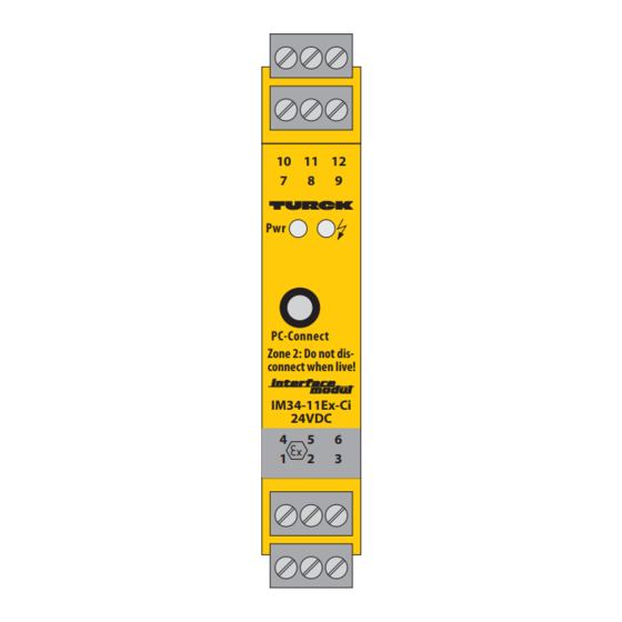
LED-Anzeigen (Fig. 1)
Pwr
grün
Betriebsbereitschaft
ó
rot
Fehler
Hinweis: Statusanzeigen, siehe Tab. 1 auf nächs-
ter Seite
Fig. 1
10
11
12
7
8
9
Pwr
PC-Connect
Zone 2: Do not dis-
connect when live!
IM34-11Ex-Ci
24VDC
4
5
6
1
2
3
1 /0112
Temperature measuring
amplifier
IM34-11Ex-Ci/24VDC
Short description
•
Inputs for thermocouples according to
IEC 60584, DIN 43710, GOST R 8.585-2001,
RTDs according to IEC 60751, DIN 43760,
GOST 6651-94 (types, see page 3),
low voltages (-160...+160 mV),
resistances (0...700 W)
•
Area of application acc. to ATEX:
II (1) G, II (1) D, II 3 G
•
Approved for installation in zone 2
•
Wire-break monitoring
•
Short-circuit monitoring, only RTDs
•
Thermocouple measured with internal,
external or adjustable cold junction
temperature
•
Galvanic isolation between input and output
circuits and supply
•
Analog current output 0/4...20 mA
•
Dielectric strength up to 2 kV
•
Temperature-linear implementation
•
Adjustable via PC interface (PC-Connect)
•
Housing with coded removeable
terminal blocks
•
Simulation of output
•
Operating voltage 24 VDC (20...30 VDC)
Terminal configuration (Fig. 2)
1, 2
Thermocouple and mV input
3 – 6
RTD/resistance input
7, 8
Analog current output (0/4...20 mA)
11,12
Supply voltage connection
24 VDC (20...30 VDC), < 1.5 W
Connection via cage clamps with captive screws,
connection profile: ≤ 1 x 2.5 mm
mit
2 x 1 mm
with wire sleeves
2
2
LED indications (Fig. 1)
Pwr
green
ó
red
Attention: Status indications, see table 1 on the
next page
Fig. 2
mV
Ω/RTD
Amplificateur de mesure
pour thermocouple
IM34-11Ex-Ci/24VDC
Description brève
•
•
•
•
•
•
•
•
•
•
•
•
•
•
Raccordement des bornes (Fig. 2)
1, 2
3 – 6
7, 8
11,12
Raccordement du câble par des cages levantes
, 2 x 1.5 mm
or
avec des vis imperdables, section raccordable:
2
2
≤ 1 x 2,5 mm
cosses
Visualisations par LED (Fig. 1)
power on
Pwr
error
ó
Conseil: visualisations de l'état, voir tableau 1 à
la page suivante
+ 1
TC
– 2
4
3
2
3
6
5
GN
4
Pwr
Entrées pour thermocouples suivant
IEC 60584, DIN 43710, GOST R 8.585-2001,
RTDs suivant IEC 60751, DIN 43760,
GOST 6651-94 (types, voir page 3),
des faibles tensions (-160...+160 mV),
résistances (0...700 W)
Champ d'application suivant ATEX:
II (1) G, II (1) D, II 3 G
Certifié pour montage en zone 2
Surveillance aux ruptures de câble
Surveillance aux courts-circuits seulement
pour RTDs
Mesure du thermocouple par compensation
du point froid interne ou externe ou
par la température du point froid réglable
Séparation galvanique entre circuits d'entrée
et de sortie et par rapport à l'alimentation
Sortie de courant analogique 0/4...20 mA
Résistance diélectrique jusqu'à 2 kV
Conversion linéaire en fonction de la
température
Réglable par interface PC (PC-Connect)
Boîtier avec blocs de bornes codés débrochables
Simulation de sortie
Tension de service 24 VDC (20...30 VDC)
Entrée pour thermocouple et mV
Entrée RTD/résistance
Sortie de cour. analogique (0/4...20 mA)
Raccordement de la tension de service
24 VDC (20...30 VDC), < 1,5 W
, 2 x 1,5 mm
ou 2 x 1 mm
2
2
verte
tension de service
rouge
défaut
to PC via
µP
IM-PROG
7 +
0/4...20 mA
8 –
R L ≤ 600 Ω
11 +
RD
24 VDC
12 –
avec
2
Advertisement
Table of Contents

Related Manuals for turck IM34-11Ex-Ci/24VDC


Summary of Contents for turck IM34-11Ex-Ci/24VDC
- Page 1 Temperaturmessverstärker Temperature measuring Amplificateur de mesure amplifier pour thermocouple IM34-11Ex-Ci/24VDC IM34-11Ex-Ci/24VDC IM34-11Ex-Ci/24VDC Gerätekurzbeschreibung Short description Description brève • • • Eingänge für Thermoelemente nach Inputs for thermocouples according to Entrées pour thermocouples suivant IEC 60584, DIN 43710, GOST R 8.585-2001, IEC 60584, DIN 43710, GOST R 8.585-2001,...
- Page 2 M34-11Ex-Ci/24VDC Tab. 1: LED-Statusanzeigen/LED status indications/Visualisation de l‘état par LED Status LED-Code Parameter in DTM Hinweis State Parameter in DTM Note Statut Paramètre en DTM Conseil Hardware-Fehler / IdEx-Timeout/ Hardware Error / ADC/ Erreur de matérial TemperatureIntern Software-Fehler / RomCrcError/ Software Error / RamError Erreur de logiciel...
- Page 3 (siehe auch devices DTM software installation”, D201354). „installation du logiciel PACTware™ et des DTM beigefügte Dokumentation „Software-Installa- The TURCK adapter IM-PROG III (to be ordered d‘appareils“, D201354). tion PACTware™ und Geräte-DTMs“, D201354). additionally – ident-no.: 7525111) is needed to Le IM-PROG III de TURCK (à...
- Page 4 M34-11Ex-Ci/24VDC Montage und Installation (Fig. 3) Mounting and installation (Fig. 3) Montage et installation (Fig. 3) Die angeschlossenen Betriebsmittel (RTD, The connected equipment (RTD, thermocouple) Les matériels électriques (RTD, thermocouple) Thermoelement) müssen die Voraussetzung must meet the requirements for use in explosion raccordés doivent remplir les exigences pour le zum Einsatz im explosionsgefährdeten Bereich hazardous areas (EN 60079-14).
- Page 5 All valid national and interna- internationaux des appareils TURCK peuvent être obtenus par Die Besonderen Bedingungen IECEx CoC sind unter tional approvals covering Turck devices are obtainable via the internet (www.turck.com). Les Conditions particulières www.iecex.com zu finden.
- Page 6 Irrtümer und Änderungen vorbehalten / Subject to change without notice / Sous réserve de modifications • © Hans Turck GmbH & Co. KG 2012 Hans Turck GmbH & Co. KG • Witzlebenstraße 7 • 45472 Mülheim/Ruhr • Germany • Tel. +49 (0) 208/4952-0 • Fax +49 (0) 208/4952-264 • more@turck.com • www.turck.com...
Need help?
Do you have a question about the IM34-11Ex-Ci/24VDC and is the answer not in the manual?
Questions and answers