Table of Contents
Advertisement
Available languages
Available languages
Quick Links
Advertisement
Chapters
Table of Contents

Related Manuals for Ego Power+ Nexus Escape


Summary of Contents for Ego Power+ Nexus Escape
- Page 1 POWER INVERTER OPERATOR’S MANUAL 56-VOLT POWER INVERTER Français p. 25 Español p. 51 MODEL NUMBER PAD5000/ PAD5000-FC WARNING: To reduce the risk of injury, the user must read and understand the Operator’s Manual before using this product. Save these instructions for future reference.
-
Page 2: Table Of Contents
TABLE OF CONTENTS FCC Statement ......... . . 4 Safety Symbols . - Page 3 READ ALL INSTRUCTIONS! READ & UNDERSTAND OPERATOR’S MANUAL WARNING: To reduce the risk of injury, fire, electric shock, user must read and understand the operator’s manual for their USB accessories and AC devices in addition to this instruction sheet. Ensure compatibility before using the power inverter. Do not use this product if any part is damaged or missing.
-
Page 4: Fcc Statement
FCC STATEMENT 1. This device complies with Part 15 of the FCC Rules. Operation is subject to the following two conditions: 1) This device may not cause harmful interference. 2) This device must accept any interference received, including interference that may cause undesired operation. -
Page 5: Safety Symbols
SAFETY SYMBOLS The purpose of safety symbols is to attract your attention to possible dangers. The safety symbols and the explanations with them deserve your careful attention and understanding. The symbol warnings do not, by themselves, eliminate any danger. The instructions and warnings they give are no substitutes for proper accident prevention measures. -
Page 6: Safety Instructions
SAFETY INSTRUCTIONS This page depicts and describes safety symbols that may appear on this product. Read, understand, and follow all instructions on the machine before attempting to assemble and operate it. Safety Alert Indicates a potential personal injury hazard. Read & To reduce the risk of injury, user must read Understand and understand the operator’s manual before... - Page 7 IMPORTANT SAFETY INSTRUCTIONS WARNING: When using this product, basic precautions should always be followed, including the following: Read all the instructions before using the product. To reduce the risk of injury, close supervision is necessary when the product is used near children.
- Page 8 When charging the internal battery, work in a well ventilated area and do not restrict ventilation in any way. Under abusive conditions, liquid may be ejected from the battery; avoid contact. If contact accidentally occurs, flush with water. If liquid contacts eyes, additionally seek medical help.
- Page 9 Prevent unintentional starting. Ensure the switch is in the off-position before connecting to battery pack, picking up or carrying the power inverter. Carrying the power inverter with your finger on the switch or energizing power inverter that has the switch on invites accidents. ...
- Page 10 Do not modify or attempt to repair the power inverter or the battery pack except as indicated in the instructions for use and care. Store idle power inverter out of the reach of children and do not allow persons unfamiliar with the power inverter or these instructions to operate the power inverter.
-
Page 11: Introduction
INTRODUCTION Congratulations on your selection of a new generation of 56V Lithium-ion power inverter. It has been designed, engineered and manufactured to give you the best possible dependability and performance. Should you experience any problem you cannot easily remedy, please contact EGO customer service center 1-855-EGO-5656. -
Page 12: Specifications
SPECIFICATIONS Input Voltage Output Wave Form Pure Sine Wave USB-A Output 3A, 9V 2A, 12V 1.5A, up to 18W 3A, 9V 2A, 12V 1.5A, USB-C Output Port 1 1.2A, 20V 0.9A, up to 18W , 9V , 12V , 15V USB-C Input/Output Port 2 , 5A Max, up to 100W 120V ~ 60Hz, 400W Continuous, 800W Peak... -
Page 13: Description
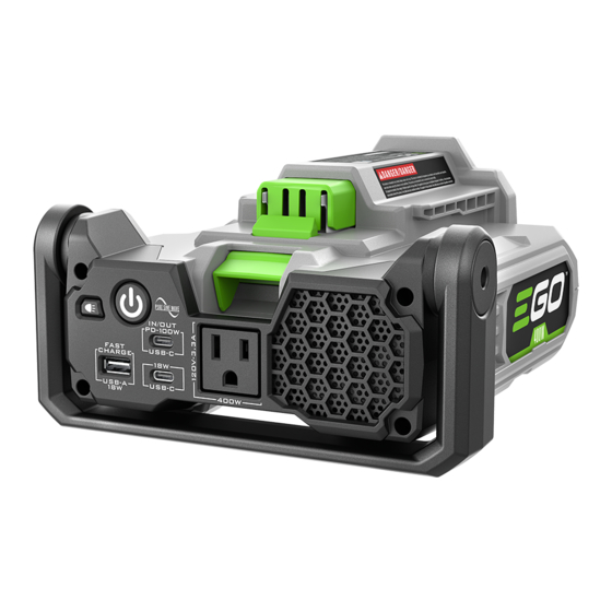
DESCRIPTION KNOW YOUR POWER INVERTER (Fig. 1) The safe use of this product requires an understanding of the information on the product and in this operator’s manual, as well as knowledge of the project you are attempting. Before using this product, familiarize yourself with all operating features and safety rules. -
Page 14: Operation
OPERATION WARNING: Do not allow familiarity with this product to make you careless. Remember that a careless fraction of a second is sufficient to inflict serious injury. WARNING: Do not modify or attempt to repair the power inverter except as indicated in the instructions for use and care. - Page 15 WARNING: Always be aware of the location of your feet, children, or pets when pressing the battery-release button. NEVER remove the battery pack at a high position. WARNING: Always remove the battery when the power inverter is not in use. TO START/STOP THE POWER INVERTER (FIG.
- Page 16 LED LIGHTS (FIG. 5) LED Button Your power inverter is equipped with two LED lights located on the bottom of the IN/OUT PD-100W unit. These lights provide illumination of FAST CHARGE USB-C low light areas. USB-A USB-C 400W To use the LED lights, press the LED button to scroll through the following light modes: LED Lights...
- Page 17 POWER BUTTON LED INDICATOR The power button features an LED indicator that communicates the working condition of the power inverter as follows: Power Inverter Working LED Indicator on Power Button LED Indicator condition Battery Pack Solid green Standby Green light gradually fading Powering connected devices in and out Orange light gradually...
- Page 18 OVER TEMPERATURE PROTECTION If the battery or inverter temperature exceeds 158°F (70°C) during operation, the temperature-protection circuit will shut off the unit in 1 minute to protect from overheating damage. The power button indicator will glow solid red for 1 minute. Allow the unit to cool until its temperature drops below 152°F (67°C) before restarting.
- Page 19 2. Press and hold the power button for more than half a second to turn the inverter ON. The LED in the power button will illuminate green when the inverter is ready to use. 3. Plug devices you want to power or charge into the power inverter’s USB ports and/or 120 volt AC output port.
-
Page 20: Maintenance
MAINTENANCE WARNING: To avoid serious personal injury, always remove the battery pack from the power inverter when cleaning or performing any maintenance. WARNING: When servicing, use only identical EGO replacement parts. Use of any other parts may create a hazard or cause product damage. To ensure safety and reliability, all repairs should be performed by a qualified service technician. -
Page 21: Troubleshooting
TROUBLESHOOTING PROBLEM CAUSE SOLUTION The power inverter does Battery pack capacity is Charge the battery not work. depleted. pack. The battery pack is too Cool the battery pack hot. until its temperature drops below 152°F (67°C). Power button LED flashes Low battery pack charge. - Page 22 PROBLEM CAUSE SOLUTION Green light does not AC output port power is This is normal operation. gradually fade in and out less than 10W. No action is needed. when powering a device connected to AC output port. 56-VOLT POWER INVERTER...
-
Page 23: Warranty
EGO LIMITED WARRANTY WARRANTY POLICY TERMS AND DURATION Chervon North America, Inc. (“Chervon North America”) provides the following Limited Warranty for EGO products to the original purchaser of EGO products. The detailed warranty period for each EGO product can be found online at http://egopowerplus.com/warranty-policy. - Page 24 or guidelines; or failure to properly service of maintain the product. This warranty also does not apply to cosmetic damage, including but not limited to scratches or dents; defects caused by normal wear and tear or otherwise due to the normal aging of the product.
- Page 25 POWER INVERTER GUIDE D’UTILISATION CONVERTISSEUR CONTINU- ALTERNATIF DE 56 VOLTS NUMÉRO DE MODÈLE PAD5000/ PAD5000-FC AVERTISSEMENT : Afin de réduire les risques de blessure, l’utilisateur doit lire et comprendre le guide d’utilisation avant d’utiliser ce produit. Conservez le présent guide afin de pouvoir le consulter ultérieurement.
- Page 26 TABLE DES MATIÈRES Déclaration relative à la FCC ....... 28 Symboles relatifs à...
- Page 27 LISEZ TOUTES LES INSTRUCTIONS! LIRE ET COMPRENDRE LE GUIDE D’UTILISATION AVERTISSEMENT: Pour réduire les risques de blessure, d’incendie et de choc électrique, l’utilisateur doit lire et comprendre le mode d’emploi de ses accessoires USB et de ses appareils à courant alternatif en plus de cette fiche d’instructions. Assurez-vous de la compatibilité...
-
Page 28: Déclaration Relative À La Fcc
DÉCLARATION RELATIVE À LA FCC 1. Cet appareil est conforme à la partie 15 des Règlements de la FCC. Son fonctionnement est soumis aux deux conditions suivantes : 1) L’appareil ne doit pas provoquer d’interférences nuisibles. 2) L’appareil doit accepter toute interférence reçue, y compris des interférences susceptibles de causer un fonctionnement non désiré. -
Page 29: Symboles Relatifs À La Sécurité
SYMBOLES RELATIFS À LA SÉCURITÉ L’objectif des symboles relatifs à la sécurité est d’attirer votre attention sur les dangers potentiels. Vous devez examiner attentivement et bien comprendre les symboles de sécurité et les explications qui les accompagnent. Les symboles d’avertissement n’éliminent pas le danger d’eux-mêmes. -
Page 30: Consignes De Sécurité
CONSIGNES DE SÉCURITÉ Cette page représente et décrit les symboles de sécurité qui peuvent figurer sur ce produit. Lisez attentivement et suivez toutes les instructions figurant sur la machine avant de l’assembler et de commencer à l’utiliser. Alerte de sécurité Indique un risque de blessure. - Page 31 CONSIGNES DE SÉCURITÉ IMPORTANTES AVERTISSEMENT: Des précautions élémentaires doivent toujours être prises lors de l’utilisation de ce produit, notamment les précautions suivantes : Lisez toutes les instructions avant de commencer à utiliser ce produit. Pour réduire le risque de blessure, une supervision attentive est nécessaire lorsque le produit est utilisé...
- Page 32 PRÉCAUTIONS PERSONNELLES Ne JAMAIS fumer ou laisser une étincelle ou une flamme à proximité de la pile. Faites preuve de prudence pour réduire le risque de faire tomber un outil métallique sur la pile. Cela pourrait provoquer des étincelles ou un court-circuit de la pile ou d’une autre pièce électrique, ce qui pourrait provoquer une explosion.
- Page 33 Risques d’incendie et de choc électrique. Utilisation dans des endroits secs seulement. N’exposez pas le bloc d’alimentation électrique à la pluie ou à un environnement humide. La pénétration d’eau dans le convertisseur continu- alternatif augmentera le risque de choc électrique. ...
- Page 34 N’utilisez qu’avec les blocs-piles et les chargeurs indiqués ci-dessous : BLOC-PILES CHARGEUR CH2100, CH2100-FC, BA1400, BA1400-FC, BA2800, BA2800-FC, CH3200, CH3200-FC, BA4200, BA4200-FC, BA1400T, BA1400T-FC, BA2242T, BA2242T-FC, BA2800T, BA2800T-FC, CH5500, CH5500-FC, BA3360T, BA3360T-FC, BA4200T, BA4200T-FC, CH2800D, CH2800D-FC, BA5600T, BA5600T-FC, BA6720T, BA6720T-FC CH7000, CH7000-FC ...
- Page 35 Entretenez les convertisseurs continu-alternatif et les accessoires. Assurez- vous que les pièces sont bien alignées et qu’il n’y a pas de pièces cassées ou qu’il n’existe aucune situation pouvant affecter le fonctionnement du convertisseur continu-alternatif. Si le convertisseur continu-alternatif est endommagé, faites-le réparer avant de vous en servir à...
-
Page 36: Introduction
INTRODUCTION Félicitations pour votre choix de la nouvelle génération de convertisseurs continu- alternatif à pile au lithium-ion de 56 V. Elle a été conçue, développée et fabriquée pour vous donner le plus possible de fiabilité et de rendement. Si vous éprouvez un problème que vous n’arrivez pas à régler facilement, veuillez communiquer avec le centre de service à... -
Page 37: Caractéristiques Techniques
SPÉCIFICATIONS Tension d’entrée Forme d’onde de sortie Onde sinusoïdale pure 3A, 9V 2A, 12V 1.5A, jusqu’à Sortie USB-A 3A, 9V 2A, 12V 1.5A, Orifice de sortie USB-C 1 1.2A, 20V 0.9A, jusqu’à 18W Orifice d’entrée/de sortie USB-C , 9V , 12V , 15V , 5A Max, jusqu’à... -
Page 38: Description
DESCRIPTION FAMILIARISEZ-VOUS AVEC VOTRE CONVERTISSEUR CONTINU- ALTERNATIF (Fig. 1) Pour que ce produit puisse être utilisé en toute sécurité, il est nécessaire de comprendre les informations figurant sur Le produit et dans son mode d’emploi, et de bien maîtriser le projet que vous voulez réaliser. Avant d’utiliser ce produit, familiarisez-vous avec toutes ses fonctionnalités et les consignes de sécurité... -
Page 39: Fonctionnement
FONCTIONNEMENT AVERTISSEMENT: Ne laissez pas l’habitude de l’utilisation de ce produit vous empêcher de prendre toutes les précautions requises. N’oubliez jamais qu’une fraction de seconde d’inattention suffit pour entraîner de graves blessures. AVERTISSEMENT: Ne modifiez pas et ne tentez pas de réparer le convertisseur continu-alternatif, sauf conformément à... - Page 40 INSTALLATION / RETRAIT DU BLOC-PILES (Fig. 2 & 3) REMARQUE: Chargez complètement le bloc-piles avant de vous en servir pour la première fois. Installation du bloc-piles (Fig. 2) Faites glisser un bloc-piles sur le convertisseur continu-alternatif comme indiqué. Assurez-vous que le loquet de verrouillage du bloc-piles se met bien en place et que le bloc-piles est bien assujetti au convertisseur continu-alternatif avant de commencer à...
- Page 41 MISE EN MARCHE / ARRÊT DU CONVERTISSEUR CONTINU- ALTERNATIF (FIG. 4) 1. Installez le bloc-piles. Bouton de 2. Pour mettre le convertisseur continu- mise sous alternatif sous tension, appuyez sur le tension/hors IN/OUT PD-100W FAST bouton d’alimentation et maintenez-le USB-C CHARGE tension USB-A...
- Page 42 VOYANT À DEL DU BOUTON DE MISE SOUS TENSION/HORS TENSION Le bouton de mise sous tension/hors tension comporte un voyant à DEL qui communique l’état de fonctionnement du convertisseur continu-alternatif comme suit : Voyant à DEL du bouton de mise État de fonctionnement du Voyant à...
- Page 43 PROTECTION CONTRE LES TEMPÉRATURES EXCESSIVES Si la température des piles ou du convertisseur dépasse 70°C / 158°F pendant le fonctionnement, le circuit de protection contre les températures excessives éteint l’équipement en une minute pour le protéger contre les dommages causés par la chaleur.
- Page 44 AVERTISSEMENT: Pour éviter tout risque de choc électrique, n’insérez pas de clou, de fil, etc. dans l’orifice de sortie c.a. AVERTISSEMENT: Risque de choc électrique et risque d’incendie. Cet équipement ne doit pas être rangé ou conservé dans un véhicule. 1.
- Page 45 N’insérez pas de clou, de fil, etc. dans les ports USB. Sinon, un court-circuit pourrait endommager les ports USB. Lors de la mise sous tension du convertisseur continu-alternatif, si le courant de sortie USB est inférieur à 100 mA et si la puissance de sortie c.a. est inférieure à 10 w, le système s’éteindra automatiquement au bout de 2 heures.
-
Page 46: Entretien
ENTRETIEN AVERTISSEMENT: Pour éviter des blessures graves, retirez toujours le bloc- piles du convertisseur lorsque vous le nettoyez ou quand vous effectuez des travaux de maintenance. AVERTISSEMENT: Lors de toute réparation, n’utilisez que des pièces de rechange EGO identiques. L’utilisation de toutes autres pièces de rechange pourrait créer un danger ou endommager le produit. -
Page 47: Dépannage
RECHERCHE DE LA CAUSE DES PROBLÈMES PROBLÈME CAUSE SOLUTION Le convertisseur continu- Le bloc-piles est Chargez le bloc-piles. alternatif ne fonctionne complètement Laissez le bloc-piles pas. déchargé. refroidir jusqu’à ce que Le bloc-piles est trop la température descende chaud. - Page 48 PROBLÈME CAUSE SOLUTION Le voyant du bouton de Autre dysfonctionnement Déconnectez votre mise sous tension/hors de l’électronique. équipement et reconnectez- tension à DEL clignote en le à nouveau, Si le même rouge pendant une minute dysfonctionnement se à raison d’un clignotement reproduit, veuillez contacter par seconde, puis il le centre de service clientèle...
-
Page 49: Garantie
GARANTIE LIMITÉE D’EGO CONDITIONS ET DURÉE DE LA POLITIQUE DE GARANTIE Chervon North America, Inc. (« Chervon North America ») accorde la Garantie limitée suivante pour les produits EGO à l’acheteur initial de produits EGO. La période de garantie détaillée de chaque produit EGO est indiquée en ligne à l’adresse http://egopowerplus.com/warranty-policy. - Page 50 garantie ne s’applique pas aux dommages causés par un accident, un abus, une mauvaise utilisation, une altération, une modification, une réparation non autorisée, un contact avec un liquide, un incendie, un tremblement de terre ou toute autre cause externe ; par une utilisation du produit en dehors des instructions, spécifications ou directives d’EGO ;...
- Page 51 POWER INVERTER MANUAL DEL USUARIO INVERSOR DE ALIMENTACIÓN DE 56 V MODELO NÚMERO PAD5000/ PAD5000-FC ADVERTENCIA: Para reducir el riesgo de lesiones, el usuario debe leer y entender el Manual del operador antes de usar este producto. Guarde estas instrucciones para consultarlas en el futuro.
- Page 52 ÍNDICE Declaración de la Comisión Federal de Comunicaciones (FCC, por sus siglas en inglés) ......54 Símbolos de seguridad .
- Page 53 LEA TODAS LAS INSTRUCCIONES! LEA Y COMPRENDA EL MANUAL DEL OPERADOR ADVERTENCIA: Para reducir el riesgo de lesiones, incendio y descargas eléctricas, el usuario debe leer y entender el manual del operador para sus accesorios USB y sus dispositivos de CA, además de esta hoja de instrucciones. Asegúrese de la compatibilidad antes de utilizar el inversor de alimentación.
-
Page 54: Declaración De La Comisión Federal De Comunicaciones
DECLARACIÓN DE LA COMISIÓN FEDERAL DE COMUNICACIONES (FCC, POR SUS SIGLAS EN INGLÉS) 1. Este dispositivo cumple con la Parte 15 de las Reglas de la FCC. Su utilización está sujeta a las dos condiciones siguientes: 1) Este dispositivo no podrá causar interferencia perjudicial. 2) Este dispositivo debe aceptar cualquier interferencia que reciba, incluyendo interferencia que pueda causar un funcionamiento no deseado. -
Page 55: Símbolos De Seguridad
SÍMBOLOS DE SEGURIDAD La finalidad de los símbolos de seguridad es atraer la atención del usuario hacia posibles peligros. Los símbolos de seguridad y las explicaciones que los acompañan merecen que usted preste una atención detenida y logre una comprensión profunda. Las advertencias con símbolo no eliminan por sí... -
Page 56: Instrucciones De Seguridad
INSTRUCCIONES DE SEGURIDAD Esta página muestra y describe los símbolos de seguridad que es posible que aparezcan en este producto. Lea, entienda y siga todas las instrucciones que se encuentran en la máquina antes de intentar ensamblarla y utilizarla. Alerta de Indica un peligro potencial de lesiones seguridad corporales. - Page 57 INSTRUCCIONES DE SEGURIDAD IMPORTANTES ADVERTENCIA: Cuando se utilice este producto, se deberán seguir siempre precauciones básicas, incluyendo las siguientes: Lea todas las instrucciones antes de utilizar este producto. Para reducir el riesgo de lesiones, se necesita supervisión estrecha cuando el producto se utilice cerca de niños.
- Page 58 PRECAUCIONES PERSONALES No fume ni permita NUNCA una chispa o una llama en las proximidades de la batería. Tenga precaución adicional para reducir el riesgo de dejar caer una herramienta metálica sobre la batería. Esto podría generar chispas o cortocircuitos en la batería u otra pieza eléctrica que pueden causar una explosión.
- Page 59 Riesgo de incendio y descargas eléctricas. Se debe usar solo en lugares secos. No exponga el inversor de alimentación a la lluvia ni a condiciones mojadas. La entrada de agua en el inversor de alimentación aumentará el riesgo de descargas eléctricas. ...
- Page 60 Utilice el producto solo con los paquetes de batería y los cargadores que se indican a continuación: PAQUETE DE BATERÍAS CARGADOR CH2100, CH2100-FC, BA1400, BA1400-FC, BA2800, BA2800-FC, CH3200, CH3200-FC, BA4200, BA4200-FC, BA1400T, BA1400T-FC, BA2242T, BA2242T-FC, BA2800T, BA2800T-FC, CH5500, CH5500-FC, BA3360T, BA3360T-FC, BA4200T, BA4200T-FC, CH2800D, CH2800D-FC, BA5600T, BA5600T-FC, BA6720T, BA6720T-FC...
- Page 61 Realice mantenimiento del inversor de alimentación y los accesorios. Compruebe si hay desalineación o rotura de las piezas y cualquier otra situación que pueda afectar al funcionamiento del inversor de alimentación. Si el inversor de alimentación está dañado, haga que sea reparado antes de utilizarlo.
-
Page 62: Introducción
INTRODUCCIÓN Felicitaciones por su selección de una nueva generación de inversor de alimentación de 56 V alimentado por ion litio. Este inversor ha sido diseñado, concebido y fabricado para ofrecerle a usted la mejor confiabilidad y el mejor rendimiento posibles. En caso de que tuviera algún problema que no pudiera resolver fácilmente, comuníquese con el Centro de Servicio al Cliente de EGO al 1-855-EGO-5656. -
Page 63: Especificaciones
ESPECIFICACIONES Tensión de entrada Forma de la onda de salida Onda sinusoidal pura 3A, 9V 2A, 12V 1.5A, hasta Salida USB-A 3A, 9V 2A, 12V 1.5A, Puerto de salida USB-C 1 1.2A, 20V 0.9A, hasta 18W , 9V , 12V , 15V Puerto de entrada/salida USB-C 2 , 5A máx., hasta 100W... -
Page 64: Descripción
DESCRIPCIÓN CONOZCA SU INVERSOR DE ALIMENTACIÓN (Fig. 1) El uso seguro de este producto requiere entender la información que se encuentra en el producto y en este manual del operador, así como tener conocimiento del proyecto que se esté intentando realizar. Antes de utilizar este producto, familiarícese con todas las características de funcionamiento y todas las normas de seguridad. -
Page 65: Utilización
UTILIZACIÓN ADVERTENCIA: No deje que la familiaridad con este producto le haga descuidarse. Recuerde que una fracción de segundo de descuido es suficiente para causar lesiones graves. ADVERTENCIA: No modifique ni intente reparar el inversor de alimentación, excepto tal y como se indique en las instrucciones de uso y cuidado. ADVERTENCIA: Este dispositivo está... - Page 66 INSTALACIÓN/DESINSTALACIÓN DEL PAQUETE DE BATERÍA (Fig. 2 y 3) NOTA: Cargue completamente el paquete de batería antes del primer uso. Para instalar el paquete de batería (Fig. 2) Deslice un paquete de batería sobre el inversor de alimentación de la manera que se muestra en la ilustración.
- Page 67 PARA ARRANCAR/PARAR EL INVERSOR DE ALIMENTACIÓN (FIG. 4) 1. Instale el paquete de batería. 2. Para ENCENDER el inversor de Botón de alimentación, presione y mantenga alimentación IN/OUT PD-100W FAST presionado el botón de alimentación USB-C CHARGE USB-A USB-C 400W durante más de medio segundo.
- Page 68 INDICADOR LED DEL BOTÓN DE ALIMENTACIÓN El botón de alimentación cuenta con un indicador LED que comunica el estado de funcionamiento del inversor de alimentación de la siguiente manera: Indicador LED del botón de Estado de funcionamiento del Indicador LED ubicado en el alimentación inversor de alimentación paquete de batería...
- Page 69 PROTECCIÓN CONTRA SOBRETEMPERATURA Si la temperatura de la batería o del inversor excede 158 °F (70 °C) durante la utilización, el circuito de protección contra sobretemperatura apagará la unidad en 1 minuto para protegerla contra los daños por sobrecalentamiento. El indicador del botón de alimentación se iluminará...
- Page 70 ADVERTENCIA: Para evitar un riesgo de descargas eléctricas, no inserte un clavo, un alambre, etc., en el puerto de salida de CA. ADVERTENCIA: Riesgo de descargas eléctricas y riesgo de incendio. Este dispositivo no se debe almacenar ni mantener en un vehículo. 1.
- Page 71 El inversor de alimentación no se puede APAGAR mientras que el cargador EGO esté cargando utilizando el puerto de entrada/salida USB-C 2. Desconecte primero el cargador USB PD del inversor y luego presione y mantenga presionado el botón de alimentación durante más de medio segundo para APAGAR el inversor. ...
-
Page 72: Mantenimiento
MANTENIMIENTO ADVERTENCIA: Para evitar lesiones corporales graves, retire siempre el paquete de batería del inversor de alimentación cuando realice limpieza o efectúe cualquier mantenimiento. ADVERTENCIA: Cuando haga servicio de ajustes y reparaciones, utilice solo piezas de repuesto EGO idénticas. Es posible que el uso de cualquier otra pieza cree un peligro o cause daños al producto. -
Page 73: Resolución De Problemas
RESOLUCIÓN DE PROBLEMAS PROBLEMA CAUSA SOLUCIÓN El inversor de alimentación La capacidad del Cargue el paquete de no funciona. paquete de batería está batería. agotada. Enfríe el paquete de El paquete de batería batería hasta que su está... - Page 74 PROBLEMA CAUSA SOLUCIÓN El inversor no puede No hay comunicación Retire los dispositivos descargar cuando se del sistema electrónico externos y reinsértelos utilizan los puertos USB-C entre el inversor y los 1 o 2. dispositivos externos APAGUE el inversor y conectados a los puertos rearránquelo.
-
Page 75: Garantía
GARANTÍA LIMITADA DE EGO TÉRMINOS Y DURACIÓN DE LA PÓLIZA DE GARANTÍA Chervon North America, Inc. (“Chervon North America”), proporciona la siguiente Garantía Limitada para los productos EGO al comprador original de productos EGO. El período de garantía detallado de cada producto EGO se puede encontrar en línea en http://egopowerplus.com/warranty-policy. - Page 76 reparación no autorizada, contacto con líquidos, incendio, terremoto u otra causa externa; utilización del producto sin seguir las instrucciones, especificaciones o pautas de EGO; o no hacer servicio de ajustes y reparaciones o no mantener adecuadamente el producto. Esta garantía tampoco se aplica a los daños cosméticos, incluyendo, pero sin limitarse a ello, rasguñaduras o abolladuras;...
Need help?
Do you have a question about the Nexus Escape and is the answer not in the manual?
Questions and answers