Table of Contents

Related Manuals for Bradbury Equipment H4441

Summary of Contents for Bradbury Equipment H4441
- Page 1 H4441 / H4443 / H4541 / H4543 WHEEL-FREE T61720 OPERATION AND MAINTENANCE INSTRUCTIONS Bradbury Equipment Date: 180918 Serial No: 153-165 Bridge Street GB- Northampton NN1 1QG England Ref.: KM/LJE Pages: 12 Tel. +44 (0) 1604 828 648...
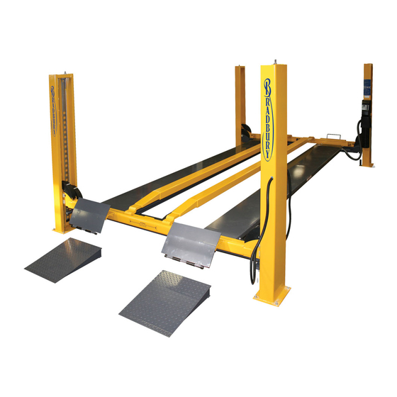
- Page 2 T61720 OPERATION AND MAINTENANCE INSTRUCTIONS This lifting device is specially developed to lift motor cars and we strongly recommend not to lift any other equipment with this automotive car lift. DESCRIPTION The lift is an electro-hydraulic 4 post surface-mounted lift with capacity ranging from 3 to 5.2 t. The lift consists of 2 pairs of posts connected with cross beams.
-
Page 3: Installation
T61720 INSTALLATION In order to come up to your expectations now and in the future the lift must be installed in strict accordance with the installation instructions and maintained according to our recommendations. Contact your distributor for the name and address of the nearest authorized service shop. FITTER INSTRUCTIONS Install the lift in strict accordance with the original installation instructions which are included in each delivery. -
Page 4: Warranty
T61720 Adjust the platforms to the wheel track of the vehicle. Place the vehicle centrally on the platforms compared to the wheel track. It is not allowed to operate the main lift while the vehicle is raised on one or two scissor jacks and it is not fastened. - Page 5 Alu rails for jack Cross beams Rails Bradbury Equipment does not accept any claim concerning the paint peeling off or corrosion damages caused by missing or insufficient cleaning or maintenance. Repair of damages: Repair of damages on the coating must be carried out immediately in order to minimize the extent of the repair.
- Page 6 T61720 One of following load distribution labels: H4443 H4543 Operation and maintenance instructions: Alternative labels:...
- Page 7 T61720 ADJUSTMENT OF CABLES Steel cables will stretch depending on the operational load and therefore require adjustment as follows: Load the lift with approximately 2500 kg (5500 lbs). Switch off air supply. Adjust wires to make the 4 ratchets engage simultineously when UP-button is activated. Raise lift to top position.
- Page 8 T61720 SERVICE High pressure cylinder replacement - main lift To be carried out by trained personne. Please contract your dealer. Raise the lift to the appropriate working height and allow the safety ratchets to engage. Remove cables from yoke. Remove lock nut and screw off yoke. If the piston rod is seized in the yoke, protect the rod surface with either rubber or fibre before using a pipe wrench.
-
Page 9: Oil Specifications
T61720 OIL SPECIFICATIONS - Full-hydraulic lift - High-pressure No lift - Scissor lift - 4-post lift - Semi-hydraulic lift - 2-post hydraulic Lubrication oil for - Mistral H (oil in lift cylinder) surface-mounted high-pressure lift - Pit jack - Servicemaster - All-purpose lift - Presses Additives:... -
Page 10: Troubleshooting Chart
T61720 TROUBLE SHOOTING CHART In case of breakdown check the following points: 1. Electricity cut 2. Main fuses 3. Motor starter 4. Electric motor 5. Cable fracture 6. Obstruction under lift If these points are found in order but the lift is still not working, the safety system has probably been activated, and the lift must not be started or repaired by unqualified staff. - Page 11 T61720 TROUBLE SHOOTING CHART (continued) SYMPTOM CAUSE REMEDY G. Unusually high Pump worn Replace pump noise level Lift overloaded Max. load - see decals Seal in high pressure Replace or renovate cylinder cylinder defective Incorrect post position Re-position posts according to installation instructions Oil pressure release valve Adjust: 4 t = 230 bar...
-
Page 12: Floor Level
The end user has been thoroughly instructed in correct use and maintenance Write any defects/faults on the enclosed note-scheme and return/fax a copy of this control CONCLUSION list (both pages 11 and 12) to: Bradbury Equipment 153-165 Bridge Street GB- Northampton NN1 1QG England Tel. - Page 13 T61720 NOTES Revision:...
Need help?
Do you have a question about the H4441 and is the answer not in the manual?
Questions and answers