
Related Manuals for cypress solutions CTM-500


Summary of Contents for cypress solutions CTM-500
- Page 1 CTM-500 MANUAL Product CTM-500 Revision Revision 1.0 MANUAL: CTM-500 3066 Beta Avenue | Burnaby, B.C. | V5G 4K4 © 2022 Cypress Solutions...
- Page 2 Notice Revision Control Description Initials Date Initial Release 28-OCT-2022 © 2022 Cypress Solutions Manual: CTM-500 (Revision 1.0)
-
Page 3: Table Of Contents
Physical Interfaces ................................ 5 SIM Card Installation ..............................7 SIM card insertion and removal ..........................8 SIM Removal Tool ............................... 9 CTM-500 Installation ..............................9 Physical Mounting ..............................9 Connect External Antennas ..........................10 Cellular (4x4 MIMO)..............................10 Wi-Fi (2x2 MIMO) ............................... 11 GNSS/GPS (1x1) ................................. -
Page 4: Notice
Wireless transmitters can cause interference with some critical operation equipment. For this reason, it is required that the RF portion of the CTM-500 wireless gateway be turned off when in the vicinity of blasting operations, medical equipment, life support equipment, or any other equipment that is susceptible to radio interference. -
Page 5: Electromagnetic Interference (Emi) - United States Fcc Information
Classe B prescrites dans la norme sur le matériel brouilleur: “Appareils Numériques”, NMB-003 édictée par le Ministre des Communications. Trademarks All brand or product names, trademarks, logos, etc. used in this manual are owned by their respective companies. © 2022 Cypress Solutions Manual: CTM-500 (Revision 1.0) -
Page 6: Product Overview
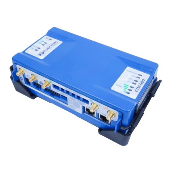
Product Overview Product Overview The CTM-500 is the next generation wireless gateway that is built with an advanced processor to process data at the highest speed. With the option of LTE-A or 5G connectivity for fixed site or mobile applications, the CTM-500 can integrate seamlessly into any environment. - Page 7 Support for two 2FF (mini) SIM cards *Refer to Appendix 2 and 3 for further detail. GENERAL PURPOSE I/O 1- Wire, SERIAL INTERFACE POWER USB-C (DEVICE/HOST) ANTENNA CONNECTORS CAN BUS 10/100/1000 (OBDII/J1939) Ethernet PHYSICAL INTERFACE - FRONT © 2022 Cypress Solutions Manual: CTM-500 (Revision 1.0)
-
Page 8: Sim Card Installation
PHYSICAL INTERFACE - BACK SIM Card Installation The CTM-500 supports two mini 2FF style SIM cards. One or two SIMS can be installed. For single SIM card installation, the SIM card may be inserted into either slot, labelled SIM1 and SIM2. -
Page 9: Sim Card Insertion And Removal
4) Close the SIM door securely by sliding it to the right until a ‘click’ is heard. Please refer to the video guide as an additional resource here. SIM INSERTED COPPER CONTACT FACING UPWARDS SIM 1 INSTALLED SIM 2 INSTALLED SIM 1+2 INSTALLED SIM REMOVAL © 2022 Cypress Solutions Manual: CTM-500 (Revision 1.0) -
Page 10: Sim Removal Tool
SIM Removal Tool The SIM removal tool is used to facilitate the removal of SIM cards. The tool is included with every CTM-500 device shipment. The opposite end of the SIM removal tool also serves as a main fuse removal tool. -
Page 11: Connect External Antennas
CTM-500 Installation The bracket can be used as drill template. This hole pattern matches the legacy Cypress Solutions devices, (CTM-200 and Oxygen 3 Plus) so no extra holes are required. MOUNTING BRACKET Connect External Antennas The CTM-500 requires external antennas for Cellular/GNSS(GPS) and Wi-Fi. Antennas should be selected based on the application and operating environment. -
Page 12: Wi-Fi (2X2 Mimo)
Vehicle ECU (OBDII/J1939) DC Power Supply Power can be supplied to the CTM-500 using an AC/DC wall adaptor to provide power to the device continuously. A DC power cable can also be connected to a DC power source between 7-32 VDC. Ignition line detection is also available that supports the CTM-500 to enter standby/suspend modes for low power applications. -
Page 13: Power Over Ethernet (Poe)
6954.2019 Power over Ethernet (PoE) Power can be supplied to the CTM-500 by using a compatible PoE (802.3 at) power supply. Connect the PoE power supply to the ETH0 port of the CTM-500. Note: PoE is only supported on the CTM-500 with the optional battery pack module installed. -
Page 14: Led Light Indicators
*Ignition cable is only required for vehicles that cannot determine the ignition state from the vehicle ECU. Please contact Cypress Solutions for additional information. LED Light Indicators There are ten LED indicators on the CTM-500 wireless gateway. © 2022 Cypress Solutions Manual: CTM-500 (Revision 1.0) - Page 15 (Solid) IPSEC ENABLED, and all tunnels CONNECTED (Flashing slowly) IPSEC ENABLED, not all tunnels are CONNECTED (OFF) IPSEC disabled (Solid) Cellular connected (Flashing quickly) Cellular connecting (Flashing slowly) Cellular not connected/idle (Cellular) (OFF) Cellular connectivity disabled © 2022 Cypress Solutions Manual: CTM-500 (Revision 1.0)
- Page 16 (Flashing slowly) SIM2 Selected, NOT Detected (OFF) SIM2 not selected to be used *Note: When Cellular data is disabled, the following will be OFF: CONNECTION, TECH, SIM 1, SIM 2, and all three Cellular lights. © 2022 Cypress Solutions Manual: CTM-500 (Revision 1.0)
-
Page 17: Configuration
Access via Ethernet Plug one end of a standard Ethernet patch cable into one of the CTM-500’s Ethernet port, and the other end into the LAN device, PC or Ethernet peripheral. The Ethernet port is compatible with 10/100/1000Base-T connection types. -
Page 18: Access Via Wi-Fi
Note: password must contain a combination of letters, numbers, or special characters. No dictionary words are permitted. The default password will be printed on the label attached to the CTM-500. Ethernet access can be disabled but before disabling ethernet access make sure you have confirmed alternate access via other mechanisms, for example, Cypress IOT. - Page 19 Configuration You will see this screen after a successful login: The left-most column contains expandable tree items for configuration. © 2022 Cypress Solutions Manual: CTM-500 (Revision 1.0)
- Page 20 Cancel, restore to default, or save any changes made to a page. Make sure to save changes to a page/tab before leaving and moving to another page/tab. After saving changes, you will see: © 2022 Cypress Solutions Manual: CTM-500 (Revision 1.0)
- Page 21 After clicking OK on the pop-up, the errors will display on the right in coloured boxes. Fix the validation errors first, then try saving again. In the upper left of the browser. After saving, changes must be applied to take effect. © 2022 Cypress Solutions Manual: CTM-500 (Revision 1.0)
-
Page 22: Power Management
ON GNSS timer if configured. Power Management is controlled either by Ignition or CAN Bus. The default configuration of the CTM-500 is to stay powered on continuously when connected to external power. © 2022 Cypress Solutions... -
Page 23: Power Accessory
Power Management Power Accessory The CTM-500 has an optional removable battery for short-term power in the case power is lost from the connection. This is not a standard accessory included with all devices. Description Part Number CTM-500 Battery 11220.9900 © 2022 Cypress Solutions... -
Page 24: General Troubleshooting Operation
Verify Cellular antennas are physically connected to the CTM- Connection/Cellular LED • CTM-500 is registered on the network and is in an area of (flashing RED) 5G/LTE coverage, but device has not obtained an IP address No internet access after •... - Page 25 10 to 15 Revert to SIM1, SIM2, seconds failsafe config CELL top LED and reboot 15 to 20 Revert to TECH, SIM1, seconds factory config SIM2, CELL top and reboot and middle LED © 2022 Cypress Solutions Manual: CTM-500 (Revision 1.0)
- Page 26 It is important to note that the LEDs on the lefthand side will act as a counter while the Reset button is held. Each light represents one second and will loop back to the beginning to continue past 5 seconds. © 2022 Cypress Solutions Manual: CTM-500 (Revision 1.0)
- Page 27 Crimp Terminals 20-24 AWG The CTM-500 can be connected with a DC power cable for direct connection to a DC power supply or with an optional AC Wall Plug adaptor that allows quick and easy connection to standard 120V AC Power.
- Page 28 Digital inputs have pull-down resistors. All general purpose I/O (GPIO) pins (i.e., all input and outputs) have transient protection. The I/O port provides for the control of 4 external devices and for monitoring 4 external inputs. © 2022 Cypress Solutions Manual: CTM-500 (Revision 1.0)
- Page 29 Digital Output GPIO Input Connection The 4 inputs may be configured in the CTM-500 for monitoring a digital DC voltage state or an analog DC voltage. All inputs are single ended. For digital state monitoring the input voltage is 0-36 volts.
- Page 30 For analog voltage monitoring the measurement range is 0 to +10 volts with 10mV resolution. The input can withstand up to 36 volts. Note that the IN GND connection is referenced to the CTM-500’s supply ground. Example of single ended analog input wiring:...
Need help?
Do you have a question about the CTM-500 and is the answer not in the manual?
Questions and answers