Advertisement
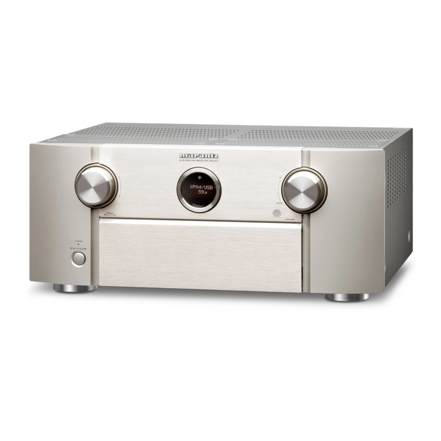
Front Panel

- Power operation button (
![]() )
)
Used to turn the power of the MAIN ZONE (room where this unit is located) on/off (standby). - Power indicator
This is lit as follows according to the power status:
 )
)- Off: Power on
- Red: Normal standby
- Orange:
- When "HDMI Pass Through" is set to "On"
- When "HDMI Control" is set to "On"
- When "IP Control" is set to "Always On"
- INPUT SELECTOR knob
This selects the input source. - Main display
This displays various pieces of information. - Remote control sensor
This receives signals from the remote control unit. - VOLUME knob
This adjusts the volume level. - Door
When you are using buttons and/or connectors behind the door, press the bottom of the door to open it. Be careful not to catch your fingers when closing the door.
![]()

With The Door Open

- Headphones jack (PHONES)
When the headphones are plugged into this jack, audio will no longer be output from the connected speakers.
NOTE: To prevent hearing loss, do not raise the volume level excessively when using headphones. - SETUP MIC jack
- iPod/USB port
- HDMI7 (AUX1)
- AUX1 INPUT connectors
- SETUP button
- ENTER button
- Cursor buttons (
![]() )
) - BACK button
- Sub display
- Dynamic Volume button (DYNAMIC VOL)
- M-DAX button/indicator
- PURE DIRECT button/indicator
- DYNAMIC EQ button
- SOUND MODE buttons
- MOVIE button
- MUSIC button
- GAME button
- Audyssey DSX® button (A-DSX)
- Speaker A/B switching button (SPKR A/B)
- HDMI OUT button
- DISPLAY button
- STATUS button
- ZONE SELECT button
- ZONE2 ON/OFF button
- ZONE3 ON/OFF button
 )
) Main Display
Main display
The input source name, sound mode, setting values and other information are displayed here.
Standard display

- Light illumination
When the power to this device is switched on, the surrounding area is lit blue. The settings can be changed so the light does not switch on. - Master volume indicator
- Input source indicator
The currently selected input source name is displayed. If the input source name has been changed using "Source Rename" in the menu, the input source name after the change is displayed.
Tuner display
These light according to the reception conditions when the input source is set to "FM".

- Lights up when the broadcast is properly tuned in.
- In the FM mode, this lights up when receiving stereo broadcasts.
Sleep timer indicator

- This lights when the sleep mode is selected.
ZONE2/ZONE3 power on display

- This lights up when ZONE2 (separate room) power is turned on.
- This lights up when ZONE3 (separate room) power is turn
Sub Display

- Input signal indicators
The respective indicator will light corresponding to the input signal. - Decoder indicators
These light when Dolby or DTS signals are input or when the Dolby or DTS decoder is running. - Audyssey ® indicator
This lights when "MultEQ ® XT32", "Dynamic EQ", "Dynamic Volume", "Audyssey DSX ® " or "Audyssey LFC - Tuner reception mode indicators
These light up according to the reception conditions when the input source is set to "HD Radio".
TUNED: Lights up when the broadcast is properly tuned in.
STEREO: Lights up when receiving FM stereo broadcasts. - Monitor output indicator
These light according to the HDMI monitor output setting. When set to "Auto(Dual)", the indicators light according to connection status. - MULTI ZONE indicator
This lights up when ZONE2 or ZONE3 (separate room) power is turned on. - Sleep timer indicator
This lights when the sleep mode is selected. - MUTE indicator
This blinks while the sound is muted. link, - Volume indicator
- Information display
The input source name, sound mode, setting values and other information are displayed here. - Front speaker indicator
This lights according to the setting of the front A and B speakers. - Input/output signal channel indicators
The channel for input/output signals is displayed according to the setting configured for "Channel Indicators".
- When "Channel Indicators" is set to "Output" (Default) These light when audio signals are being output from the speakers.
- When "Channel Indicators" is set to "Input" These light corresponding to the channels that include the input signals.
When playing HD Audio sources, the EXT indicator lights when a signal from an extension channel (a channel other than the front, center, surround, surround back, front height, front wide or LFE channel) is input.
Rear Panel

- FM/AM antenna terminal (ANTENNA)
- Analog audio connectors
(ANALOG AUDIO IN/ANALOG AUDIO OUT) - PRE OUT connectors
- 7.1ch input connectors (7.1CH IN)
- Speaker terminals (SPEAKER SYSTEMS)
- AC inlet (AC IN)
- Component video connectors
(COMPONENT VIDEO IN/COMPONENT VIDEO OUT) - Video connectors (VIDEO IN/VIDEO OUT)
- HDMI connectors
- REMOTE CONTROL connectors
- M-XPort connector
- FLASHER IN jack
Used when using a control BOX or other such control devices to control this unit. - Digital audio connectors
(DIGITAL AUDIO IN) - Network connector (NETWORK)
- SIGNAL GND terminal
- RS-232C connector
- DC OUT jacks
NOTE
Do not touch the inner pins of the connectors on the rear panel.
Electrostatic discharge may cause permanent damage to the unit.
Remote Control


- Display
- LEARN indicator
This is lit when setting the learning function for the remote control unit. - Information display
- This displays "AVR" when operating this unit.
- This displays the input source name when operating an external device.
- This displays "TV" when operating TV.
- Indicator
This is lit when signals are sent from the remote control unit.
- LEARN indicator
- AVR operation button
When preset codes are registered to the remote control unit, press this button and then operate the menu on the unit. - SET button
This is used for various settings on the remote control unit.
- "Operating external devices with the remote control unit".
- "Operating learning function".
- "Setting the back light".
- "Specifying the zone used with the remote control unit".
- ZONE SELECT button
These switch the zone (MAIN ZONE, ZONE2, ZONE3) that is operated through the remote control unit.
- "Playback in ZONE2/ZONE3".
- "Menu operations"
- Device operation buttons (DEVICE ON/OFF / DEVICE MENU)
These turn the power of external devices on/off and call up menus.
Preset codes need to be registered in order to use these buttons. - Input source select buttons
These select the input source.
- Channel/page search buttons (CH/PAGE
![]() )
)
These select radio stations registered to presets or switch pages. - SLEEP button
This sets the sleep timer. - Information button (INFO)
This displays the status information on the TV screen. - Cursor buttons (
![]() )
)
These select items. - BACK button
This returns to the previous screen. - HOME button
This takes you to the Home screen (Top screen) when the input source is Online Music or iPod/USB. - Device control buttons
These perform playback related operations.
 )
) )
)- Skip buttons (
![]() )
) - Play button (
![]() )
) - Search buttons (
![]() )
) - Pause button (
![]() )
) - Stop button (
![]() )
)
 )
) )
) )
) )
) )
)Tuning up / Tuning down buttons (TUNE +, –)
These select either FM broadcast or AM broadcast.
- FAVORITE STATION buttons (1 – 4)
With a single press of these, you can call up registered radio stations and contents - SOUND MODE buttons
These select the sound mode.
- MOVIE button
- MUSIC button
- GAME button
- PURE button
- Number buttons
These enter numbers into the unit. - Remote control signal transmitter
This transmits signals from the remote control unit. - POWER button
This turns the power on/off. - TV operation buttons (TV X / TV MENU / TV INPUT)
These turn the TV power on/off, switch the TV input and call up menus.
Preset codes need to be registered in order to use these buttons." - Light button
This turns on the backlight for approx. 2 seconds. - VOLUME buttons (
![]() )
)
These adjust the volume level - MUTE button.
This mutes the output audio. - OPTION button
This displays the option menu on the TV screen. - ENTER button
This determines the selection. - SETUP button.
This displays the menu on the TV screen.
 )
)Reset

Back up the settings before resetting the microprocessor. Most settings are reset to the factory default values after performing this procedure. This means that all the settings data will be completely lost if it's not previously saved.
Reset procedure:
With the power off, press and hold the "A-DSX" button, "GAME" button, and "POWER" button simultaneously on the AVR for a few seconds until "INITIALIZED" appears on the AVR's display

Resetting the micro is a procedure used to "reboot" the microprocessor to restore its normal operation when it temporarily freezes, locks up, or behaves erratically. Resetting the microprocessor, erases any saved settings you may have previously programmed into the unit Issues that can affect the performance of the microprocessor:
- A jolt of static electricity
- Current surge through an input
Before resetting the microprocessor;
- Check all connections carefully
- Check for setup errors
- Back up your settings. You may also want to write down your preferred settings for easier task of setting up the AVR after reset.
Note: The Web (Browser) Control feature can be used to back up your settings by saving a configuration file on your hard drive. For this feature, we recommend using one of the following web browsers: Internet Explorer 10 and above, Mozilla Firefox 24 and above, Google Chrome 29 and above, and Safari 5.x and above.
Note: If you had an installer setup your system, please first contact your installer to see if they can reset and then setup your system again as there may be specific EQ calibrations (Audyssey) that the installer will need to perform.
Accessories

Specifications
| Audio Section | |||
| Power amplifier | Rated output | Front | 125 W + 125 W (8 Ω/ohms, 20 Hz – 20 kHz with 0.08% T.H.D.) |
| Center | 125 W (8 Ω/ohms, 20 Hz – 20 kHz with 0.08% T.H.D.) | ||
| Surround | 125 W + 125 W (8 Ω/ohms, 20 Hz – 20 kHz with 0.08% T.H.D.) | ||
| Surround back / Front wide/Front Height | 125 W + 125 W (8 Ω/ohms, 20 Hz – 20 kHz with 0.08% T.H.D.) | ||
| Maximum effective output power: | Front | 195 W + 195 W (6 Ω/ohms, 1 kHz with 10% T.H.D.) | |
| Center | 195 W + 195 W (6 Ω/ohms, 1 kHz with 10% T.H.D.) | ||
| Surround | 195 W + 195 W (6 Ω/ohms, 1 kHz with 10% T.H.D.) | ||
| Surround back / Front wide/Front Height | 195 W + 195 W (6 Ω/ohms, 1 kHz with 10% T.H.D.) | ||
| Output connector | 6 – 8 Ω/ohms | ||
| Analog | Input sensitivity/Input impedance | 200 mV | |
| Frequency response | 10 Hz – 100 kHz — +1, –3 dB (Direct mode) | ||
| S/N | 96 dB (IHF–A weighted, Direct mode) | ||
| Distortion | 0.008% (20 Hz – 20 kHz) (Direct mode) | ||
| Rated output | 1.2 V | ||
| Digital | D/A output | Rated output | 2 V (at 0 dB playback) |
| Total harmonic distortion | 0.008% (1 kHz, at 0 dB) | ||
| S/N ratio | 102 dB | ||
| Dynamic range | 100 dB | ||
| Digital input | Format | Digital audio interface | |
| Phono equalizer (PHONO input — MEDIA PLAYER OUT) | Input sensitivity | 2.5 mV | |
| RIAA deviation | ±1 dB (20 Hz to 20 kHz) | ||
| S/N | 74 dB (IHF-A) | ||
| Rated output | 150 mV | ||
| Distortion factor | 0.03% (1 kHz, 3 V) | ||
| Video section | |||
| Standard video connectors | Input/output level and impedance | 1 Vp-p, 75 Ω/ohms | |
| Frequency response | 5 Hz -10MHz, 0, - 3dB | ||
| Color component video connector | Input/output level and impedance | Y signal | 1 Vp-p, 75 Ω/ohms |
| PB/CB signal | 0.7 Vp-p, 75 Ω/ohms | ||
| PR/CR signal | 0.7 Vp-p, 75 Ω/ohms | ||
| Frequency response | 5 Hz - 60MHz – 0, -3dB | ||
| Tuner section | |||
| | FM | AM | |
| Note: µV at 75 Ω/ohms, 0 dBf = 1x10-15W | |||
| Reception frequency range | 87.50 MHz - 107.90 MHz | 530 KHz - 1710 KHz | |
| Effective sensitivity | 1.5 µV (14.8 dBf) | 20µV | |
| S/N ratio (IHF-A) | Mono | 78 dB | |
| Stereo | 68 dB | ||
| HD | 85dB | 85dB | |
| Distortion (1 KHz) | Mono | 0.1 % | |
| Stereo | 0.2 % | ||
| HD | 0.02% | 0.02% | |
| General section | |||
| Power supply | AC 120V, 60Hz | ||
| Power consumption | 670W | ||
| Power consumption in standby mode | 0.2W | ||
| Power consumption in CEC standby mode | 0.5W | ||
| Power consumption in network standby mode | 2.7W | ||
| For purpose of improvement, specifications and design are subject to change without notice. | |||

Documents / ResourcesDownload manual
Here you can download full pdf version of manual, it may contain additional safety instructions, warranty information, FCC rules, etc.
Download Marantz SR7007 - Integrated Network AV Receiver Manual
Advertisement


Need help?
Do you have a question about the SR7007 and is the answer not in the manual?
Questions and answers