Table of Contents
Advertisement
EN
2
Manual No. FIL.WAMFLO_FN200.EX.M.A7.0522.EN
ORIGINAL INSTRUCTIONS IN ENGLISH
WAMGROUP S.p.A.
Via Cavour, 338
I-41030 Ponte Motta
Cavezzo (MO) - ITALY
WAMFLO
FOOD
FN200X
ROUND DUST COLLECTORS
FOR POTENTIALLY EXPLOSIVE
ATMOSPHERES AREAS
ASSEMBLY AND
MAIN INSTRUCTIONS
FOR USE AND
MAINTENANCE
Issue: A7
Latest update: May 2022
Code:
063002448
Division: FIL
+ 39 / 0535 / 618111
fax
+ 39 / 0535 / 618226
e-mail
info@wamgroup.com
internet
www.wamgroup.com
®
Advertisement
Table of Contents

Related Manuals for WAM WAMFLO FOOD FN200X


Summary of Contents for WAM WAMFLO FOOD FN200X
- Page 1 WAMFLO ® FOOD FN200X ROUND DUST COLLECTORS FOR POTENTIALLY EXPLOSIVE ATMOSPHERES AREAS ASSEMBLY AND MAIN INSTRUCTIONS FOR USE AND MAINTENANCE Manual No. FIL.WAMFLO_FN200.EX.M.A7.0522.EN Code: Issue: A7 Latest update: May 2022 063002448 Division: FIL ORIGINAL INSTRUCTIONS IN ENGLISH WAMGROUP S.p.A. + 39 / 0535 / 618111 Via Cavour, 338 + 39 / 0535 / 618226 I-41030 Ponte Motta...
- Page 2 All the products described in this catalogue are manufactured according to WAMGROUP S.p.A. Quality System procedures. The Company’s Quality System, certified in July 1994 according to International Standards UNI EN ISO 9002 and extended to the latest release of UNI EN ISO 9001, ensures that the entire production process, starting from the processing of the order to the technical service after delivery, is carried out in a controlled manner that guarantees the quality standard of the product.
-
Page 3: Table Of Contents
WAMFLO FN200X 05.22 ® INDEX FIL.WAMFLO_FN200.EX.M.A7.0522.EN Issue: A7 TABLE OF CONTENTS 1.0 GENERAL INFORMATION ........................1 1.1 Scope of the Manual ......................... 1 1.2 Symbols ............................2 1.3 Glossary and terminology ......................... 4 1.4 Manufacturer’s data and identification of equipment ................. 5 1.5 Request for assistance ........................ - Page 4 WAMFLO FN200X 05.22 ® INDEX FIL.WAMFLO_FN200.EX.M.A7.0522.EN Issue: A7 4.0 INFORMATION REGARDING HANDLING AND TRANSPORT............. 33 4.1 Type of packaging ........................... 33 4.2 Reception of goods ......................... 34 4.3 Lifting and unloading methods ......................35 5.0 INSTALLATION AND FIXING ......................... 38 5.1 General recommendations for installation ..................
-
Page 5: General Information
WAMFLO FN200X 05.22 ® 1.0 GENERAL INFORMATION FIL.WAMFLO_FN200.EX.M.A7.0522.EN Issue: A7 1.1 Scope of the Manual This Manual has been prepared by the Manufacturer to provide the operating technical information for instal- lation, operation and maintenance of the equipment concerned. The Manual, which is an integral part of the equipment concerned, must be preserved throughout the life of the equipment in a known easily accessible place, available for consultation whenever required. -
Page 6: Symbols
WAMFLO FN200X 05.22 ® 1.0 GENERAL INFORMATION FIL.WAMFLO_FN200.EX.M.A7.0522.EN Issue: A7 1.2 Symbols To highlight certain parts of the text, for purposes of safety, or to indicate important information, certain symbols are used, the meaning of which is described below. It is important to comply with and scrupulously follow the information highlighted by the symbols. Danger - Warning Indicates situations of serious danger which, if ignored, can be risky for the health and safety of per- sons. - Page 7 WAMFLO FN200X 05.22 ® 1.0 GENERAL INFORMATION FIL.WAMFLO_FN200.EX.M.A7.0522.EN Issue: A7 List of safety and information symbols Symbol Symbol description representation Danger sign: indicates danger of electric shock caused by the presence of powered components inside the junction box or control panel. Obligation: read this Manual before carrying out any action on the equipment con- cerned.
-
Page 8: Glossary And Terminology
WAMFLO FN200X 05.22 ® 1.0 GENERAL INFORMATION FIL.WAMFLO_FN200.EX.M.A7.0522.EN Issue: A7 1.3 Glossary and terminology Operator: person appropriately trained and authorized by the Production Manager for setting up the equip- ment concerned and carrying out routine maintenance. Installer: organization with specialized technicians and appropriate equipment for carrying out risk-free instal- lation and extraordinary maintenance. -
Page 9: Manufacturer's Data And Identification Of Equipment
WAMFLO FN200X 05.22 ® 1.0 GENERAL INFORMATION FIL.WAMFLO_FN200.EX.M.A7.0522.EN Issue: A7 1.4 Manufacturer’s data and identification of equipment Important Do not change the data on the identification plate. Keep the ID plates clean, intact and legible as regards the data they contain. If the ID plate is damaged or is no longer legible (even just one informative element on it) contact the Manufacturer for a new ID plate and replace it. -
Page 10: Request For Assistance
WAMFLO FN200X 05.22 ® 1.0 GENERAL INFORMATION FIL.WAMFLO_FN200.EX.M.A7.0522.EN Issue: A7 1.5 Request for assistance For all technical assistance, contact the Manufacturer’s service network. For all requests, provide the equipment identification data, the type of problem encountered and all other infor- mation which could be useful for identifying the problem. -
Page 11: Information Regarding Safety
WAMFLO FN200X ® 05.22 2.0 INFORMATION REGARDING SAFETY FIL.WAMFLO_FN200.EX.M.A7.0522.EN Issue: A7 2.1 General safety prescriptions Read the Instruction Manual carefully and strictly follow the instructions it includes, especially those regarding safety. Most accidents at the workplace are caused by negligence, failure to follow the most elementary safety regulations and incorrect or improper use of tools and equipment. -
Page 12: Safety Prescriptions For Installation
WAMFLO FN200X ® 05.22 2.0 INFORMATION REGARDING SAFETY FIL.WAMFLO_FN200.EX.M.A7.0522.EN Issue: A7 2.3 Safety prescriptions for installation Before starting with installation, a “Safety Plan” must be implemented to safeguard the personnel di- rectly involved and those who carry out operations in the surrounding area. All the laws must be strictly applied, especially those concerning workplace safety. -
Page 13: Safety Recommendations On Biological Risks
WAMFLO FN200X ® 05.22 2.0 INFORMATION REGARDING SAFETY FIL.WAMFLO_FN200.EX.M.A7.0522.EN Issue: A7 Apart from invalidation of the warranty, the Manufacturer declines all responsibility for damage to objects and harm to persons deriving from the use of non-original spare parts or due to modifications made during repairs without express written authorization. -
Page 14: Technical Information
WAMFLO FN200X ® 05.22 3.0 TECHNICAL INFORMATION FIL.WAMFLO_FN200.EX.M.A7.0522.EN Issue: A7 3.1 General description of the equipment WAMFLO is a range of dust collectors are used for both venting and suction applications. ® The filters consist of: - round stainless steel body; - vertically mounted filter elements;... -
Page 15: Limits Of Use
WAMFLO FN200X ® 05.22 3.0 TECHNICAL INFORMATION FIL.WAMFLO_FN200.EX.M.A7.0522.EN Issue: A7 3.3 Limits of use The WAMFLO filters operate under the following conditions: ® 1) Maximum permitted temperatures of the air flow: POSITIVE: 80° C continuous 100 °C peak, , maximum 60s NEGATIVE: -20 °C NOTE: For pneumatic timer, the minimum temperature is - 5 °C (-15 °... -
Page 16: Compliance With The Atex Directive
WAMFLO FN200X ® 05.22 3.0 TECHNICAL INFORMATION FIL.WAMFLO_FN200.EX.M.A7.0522.EN Issue: A7 VALUES FOR ST1, ST2 CLASSES The filter has been designed and tested to work with dust having explosion class St1, St2. WAMFLO ATEX has a structural resistance of Pred = 1 bar (10.000 mm H O, 1000 millibar, 100 KPascal). -
Page 17: Notes On Safety Standards
® potentially explosive atmospheres as defined in the ATEX Directives. In the event it is ordered a filter version equipped with anti-explosion panel (option) and the dedicated WAM ® hopper, the resulting unit body + panel + hopper represents a complete system, entirely suitable to ATEX Di- rective (within the limits of use defined in this manual). -
Page 18: Residual Risks
WAMFLO FN200X ® 05.22 3.0 TECHNICAL INFORMATION FIL.WAMFLO_FN200.EX.M.A7.0522.EN Issue: A7 Danger - Warning If an inspection hatch is present, before starting up the equipment, make sure the knobs have been closed tight. Failure to tighten the knobs will result in partial efficiency of the sealing gaskets which will, in turn, make the filter a potential source of explosive atmospheres (leakage of dusts) and alter the capacity for resistance to overpressure. -
Page 19: Main Components
WAMFLO FN200X ® 05.22 3.0 TECHNICAL INFORMATION FIL.WAMFLO_FN200.EX.M.A7.0522.EN Issue: A7 3.8 Main components ITEM DESCRIPTION MATERIAL THICKNESS FINISHING Filter body SS 304 1 mm Seal frame 6 mm SS 304 / SS 316 Compressed air tank Aluminium 3 mm Clear anodizing Solenoid valves Aluminium Black matte cataphoresis... -
Page 20: Operating Principle
WAMFLO FN200X ® 05.22 3.0 TECHNICAL INFORMATION FIL.WAMFLO_FN200.EX.M.A7.0522.EN Issue: A7 3.9 Operating principle The dirty air enters the dust collector body (1) where dust is separated by the filter elements (8). The dust drops back into the silo, hopper, or bin after an automatic pulse-jet cleaning system (3+4+5) has removed it from the filter elements. -
Page 21: Noise Level
Noise dB (A) Type 0.75 All the data indicated in the Table concern the standard WAM tests: ® - filter on DK hopper and Ø 100 mm L = 3000 mm tubes at intake and L = 2000 mm at outlet. -
Page 22: Environmental Operating Limits
WAMFLO FN200X ® 05.22 3.0 TECHNICAL INFORMATION FIL.WAMFLO_FN200.EX.M.A7.0522.EN Issue: A7 DAMPING CURVES SLA00 SLB00 SLC00 SLD00 SLE00 FREQUENCY (Hz) Danger - Warning Depending on the installation site, the installer must adopt suitable systems (barriers, etc.), if neces- sary, to maintain the noise levels within the legally permitted limits. 3.13 Environmental operating limits Unless otherwise specified, the equipment concerned may be used only within the limits indicated. -
Page 23: Options - Filter Type
WAMFLO FN200X ® 05.22 3.0 TECHNICAL INFORMATION FIL.WAMFLO_FN200.EX.M.A7.0522.EN Issue: A7 3.15 Options - Filter type In addition to the standard version, depending on the type of application and the dimension requirements, the WAMFLO filters can be manufactured in the following versions: ®... - Page 24 WAMFLO FN200X ® 05.22 3.0 TECHNICAL INFORMATION FIL.WAMFLO_FN200.EX.M.A7.0522.EN Issue: A7 ROUND FILTERS IN NEGATIVE PRESSURE They are employed in “negative” pneumatic conveying processes: a pump with max -6000 mm H O head po- sitioned near the filter sets the entire filter in negative pressure. To avoid damage to the structure, the following modifications are made to the standard model: •...
-
Page 25: Options: Coupling Type
WAMFLO FN200X ® 05.22 3.0 TECHNICAL INFORMATION FIL.WAMFLO_FN200.EX.M.A7.0522.EN Issue: A7 3.16 Options: Coupling type The connections between the body sections are made by means of welded flanges having increased thickness with interposed gasket, bolted to each other. -
Page 26: Options: Filter Outlet
WAMFLO FN200X ® 05.22 3.0 TECHNICAL INFORMATION FIL.WAMFLO_FN200.EX.M.A7.0522.EN Issue: A7 3.17 Options: Filter outlet For WAMFLO filters a series of options for filter outlet can be chosen (in the box 18 of the modular key): ® Version with connection for Standard version Version with fan centralised dust suction... -
Page 27: Options: Rain Cover
WAMFLO FN200X ® 05.22 3.0 TECHNICAL INFORMATION FIL.WAMFLO_FN200.EX.M.A7.0522.EN Issue: A7 3.18 Options: Rain cover The weather protection cover is made of 1mm thick SS 304 with 2B finishing. The locking hook, also made of SS 304, can be padlocked. The hinges are provided with a safety system consisting of a hook which automatically locks the cover in the open position to prevent it from getting detached. -
Page 28: Options- Upper Flanged Connection For Standard Filters
Issue: A7 3.19 Options- Upper flanged connection for standard filters UPPER CONNECTION FOR STANDARD FILTERS The upper connection for standard filters can be chosen as an option for connecting the WAM filter to a cen- ® tralized suction system or to a non - WAM fan. -
Page 29: Options- Lateral Flanged Connection For Standard Filters
WAMFLO FN200X ® 05.22 3.0 TECHNICAL INFORMATION FIL.WAMFLO_FN200.EX.M.A7.0522.EN Issue: A7 3.20 Options- Lateral flanged connection for standard filters In addition to the upper external connection it is possible to choose a lateral external connexion which, it is available for air jet cleaning system and vibrated cleaning system. No. -
Page 30: Options- Fans
WAMFLO FN200X ® 05.22 3.0 TECHNICAL INFORMATION FIL.WAMFLO_FN200.EX.M.A7.0522.EN Issue: A7 3.21 Options- Fans VERSION WITH FAN The connection between fan and upper body is always of the flanged type. Ø Type 0.75 0.75 0.75 0.75 1000 1061... -
Page 31: Fans - Combinations
WAMFLO FN200X ® 05.22 3.0 TECHNICAL INFORMATION FIL.WAMFLO_FN200.EX.M.A7.0522.EN Issue: A7 3.22 Fans - combinations Possible filter / fan combinations Ø DUST COLLECTOR Type ø 400 ø 600 ø 800 ø 1000 0.75 • • • • • • • • •... -
Page 32: Options - Fan Voltage / Frequency
WAMFLO FN200X ® 05.22 3.0 TECHNICAL INFORMATION FIL.WAMFLO_FN200.EX.M.A7.0522.EN Issue: A7 3.23 Options - Fan voltage / frequency • • • 1) ELECTRIC MOTOR The standard motors are asynchronous, three-phase, with B5 aluminium or cast iron casing, 2 poles, protec- tion degree IP55, isolation class F, with the following voltages and frequencies (see modular key box 19). The motors are constructed according to the IEC-UNELMEC standards. -
Page 33: Options - Anti-Explosion Panel
ATEX filters can be pre-arranged for the installation of anti-explosion panel. The prearrange- ® ment is available for diameters 600, 800 and 1000 and consists of a membrane holder (A) bolted to the filter. The membrane (B) can be provided by WAM or purchased by the customer elsewhere. Both the membrane ®... -
Page 34: Motor Absorption
WAMFLO FN200X ® 05.22 3.0 TECHNICAL INFORMATION FIL.WAMFLO_FN200.EX.M.A7.0522.EN Issue: A7 3.25 Motor absorption Standard motors 50 Hz - 2 poles Cs/Cn Is/In Cmax/ Locked Locked Size Rated Cn Max. Freq. VOLTAGE CURRENT CURRENT Speed rotor rotor cur- Weight Frame power Poles torque/ (Hz) -
Page 35: Cleaning System Voltage / Frequency
FN200X ® 05.22 3.0 TECHNICAL INFORMATION FIL.WAMFLO_FN200.EX.M.A7.0522.EN Issue: A7 3.26 Cleaning system voltage / frequency Use the field 14 to selected the standard coil WAM® or no coil: Modular key Ref. COILS AVAILABLE SUITABLE TO WAM PANELS ® No coil 24V 50/60 Hz 3.27 Options: Board accessories... -
Page 36: Safety And Information Signs
WAMFLO FN200X ® 05.22 3.0 TECHNICAL INFORMATION FIL.WAMFLO_FN200.EX.M.A7.0522.EN Issue: A7 3.29 Safety and information signs Danger - Warning Follow the signs on the plates. Ensure the plates are legible; otherwise clean them and replace the damaged ones, applying them in their original position. -
Page 37: Information Regarding Handling And Transport
The filter is supplied on a pallet and wrapped in stretch film. Before getting packed on the pallet, each filter is individually is covered with a bag in order to avoid contamination and dirt during transport and storage. WAM s.p.a. CAVEZZO... -
Page 38: Reception Of Goods
WAMFLO FN200X ® 05.22 4.0 INFORMATION REGARDING HANDLING AND TRANSPORT FIL.WAMFLO_FN200.EX.M.A7.0522.EN Issue: A7 The signs for safe lifting and handling are shown on all the packages. A) Fragile: indicates that the package has to be handled and lifted carefully to avoid damage. -
Page 39: Lifting And Unloading Methods
WAMFLO FN200X ® 05.22 4.0 INFORMATION REGARDING HANDLING AND TRANSPORT FIL.WAMFLO_FN200.EX.M.A7.0522.EN Issue: A7 4.3 Lifting and unloading methods Danger - Warning Carry out the lifting and handling operations according to the information indicated on the equipment and in the Manufacturer’s Operation Manual. The person authorized for unloading operations has to make sure all the necessary measures are adopt- ed to ensure his or her safety and the safety of other persons directly involved. - Page 40 WAMFLO FN200X ® 05.22 4.0 INFORMATION REGARDING HANDLING AND TRANSPORT FIL.WAMFLO_FN200.EX.M.A7.0522.EN Issue: A7 - Loosen the screws of the box - Remove the box NOTE: The packaging material has to be disposed off or recycled in compliance with the standards in force. The operation is in charge of the installer.
- Page 41 WAMFLO FN200X ® 05.22 4.0 INFORMATION REGARDING HANDLING AND TRANSPORT FIL.WAMFLO_FN200.EX.M.A7.0522.EN Issue: A7 Greasing devices Unload the packages from the means of transport and place them on a flat surface which can ensure the sta- bility.
-
Page 42: Installation And Fixing
WAMFLO FN200X ® 05.22 5.0 INSTALLATION AND FIXING FIL.WAMFLO_FN200.EX.M.A7.0522.EN Issue: A7 5.1 General recommendations for installation Important The filters are packed so as to minimize the possibility of contamination during transport and storage. To eliminate contamination residual risks generated by long journeys or long shut downs periods, run a cleaning and sanitization cycle before starting it up. - Page 43 WAMFLO FN200X ® 05.22 5.0 INSTALLATION AND FIXING FIL.WAMFLO_FN200.EX.M.A7.0522.EN Issue: A7 Installation on dust collector hopper The equipment supplied is provided with perimeter seal to be inserted between the dust collector and the bot- tom ring. Tighten the bolts by applying a torque of 10 Nm. Seal Positioning the seal...
-
Page 44: Positioning The Filter Flange
WAMFLO FN200X ® 05.22 5.0 INSTALLATION AND FIXING FIL.WAMFLO_FN200.EX.M.A7.0522.EN Issue: A7 5.2 Positioning the filter flange Danger - Warning During installation of the prearrangements as well as during the installation of the filter, take due pre- cautions to avoid falling through the silo opening. The person authorized to carry out operations must implement all necessary measures to ensure their safety and the safety of the people directly involved. -
Page 45: Emissions Sampling Kit
5) Connect the hose pipes to the related connections and fix by means of the clamps (see Fig.4). 6) Fit back he cover. Fig. 4 NOTE: After having sampled the emissions, WAM recommends removing the slits occlusion flanges to allow ® the filter operating in normal conditions. -
Page 46: Installing The Anti-Explosion Panel
ATEX can be pre-arranged for the installation of anti-explosion panel. The prearrange- ® ment consists of a membrane holder (A) bolted to the filter (C). The membrane (B) can be provided by WAM ® or purchased by the customer elsewhere. Both the membrane holder and the membrane are supplied in sepa- rate packagings. -
Page 47: Safety Prescriptions For Installation
WAMFLO FN200X ® 05.22 5.0 INSTALLATION AND FIXING FIL.WAMFLO_FN200.EX.M.A7.0522.EN Issue: A7 3. Before fitting the panel, ensure the values on the plate match the envisaged operating conditions. 4. Then centre the panel between the flanges/frames. To improve the hold between the disc and flanges/ frames, insert a soft gasket (KlingerSil C4400, EPDM or similar) on the process side, or turn the surfaces of the flange. - Page 48 St1 and St2 type dust - Flame length (calculated according to EN 14491) = LF (see the table below). Valid only for filters provided with the hopper, anti-explosion panel and its accessories supplied by WAM. Minimum Minimum...
- Page 49 WAMFLO FN200X ® 05.22 5.0 INSTALLATION AND FIXING FIL.WAMFLO_FN200.EX.M.A7.0522.EN Issue: A7 To the LF value it must be added a further safety margin defined by the user so to obtain a safe distance. If the filter is applied on silos, and other containers, the user/installer must calculate the LF value on the basis of the dimensions of the whole unit .
-
Page 50: Electronic Board - Connection And Settings
WAMFLO FN200X ® 05.22 5.0 INSTALLATION AND FIXING FIL.WAMFLO_FN200.EX.M.A7.0522.EN Issue: A7 5.6 Electronic board - Connection and settings For the electrical connection and settings of the new Filcontrol Time and Filcontrol Connect Electronic Boards please check the related manual (file name ELECTRONIC BOARDS FILCONTROL TIME &... -
Page 51: Information Regarding Use
- Avoid consecutive start-ups of the motor as it involves continuous overloads leading to overheating of the electrical parts. Before restarting leave it to cool sufficiently. - Be reminded that WAM fans are fitted with their own sealed single-block bearings, unless otherwise speci- ®... -
Page 52: Machine Shut-Down At The End Of The Work Cycle
WAMFLO FN200X ® 05.22 6.0 INFORMATION REGARDING USE FIL.WAMFLO_FN200.EX.M.A7.0522.EN Issue: A7 6.2 Machine shut-down at the end of the work cycle 1) Shut down the filter without disconnecting it from the power supply (according to the settings of the board, the end of cycle cleaning gets automatically enabled on the basis of the number of cycles pre-configured on the electronic board. -
Page 53: Information Regarding Maintenance
WAMFLO FN200X ® 05.22 7.0 INFORMATION REGARDING MAINTENANCE FIL.WAMFLO_FN200.EX.M.A7.0522.EN Issue: A7 Danger - Warning Before carrying out any maintenance activity, activate all the safety devices to ensure the safety of the persons involved in the operations and those nearby Set the filter in safety condition (see "Glossary and Terminology"). Wear suitable personal protection equipment;... -
Page 54: Cleaning The Equipment (The Machine)
WAMFLO FN200X ® 05.22 7.0 INFORMATION REGARDING MAINTENANCE FIL.WAMFLO_FN200.EX.M.A7.0522.EN Issue: A7 7.1 Cleaning the equipment (the machine) Clean the outside part of the equipment (the machine) using a vacuum cleaner to prevent dispersal of dust in the environment and in the surrounding area; or use a moist cloth. Do not use compressed air. -
Page 55: Replacement Of Parts
WAMFLO FN200X ® 05.22 8.0 REPLACEMENT OF PARTS FIL.WAMFLO_FN200.EX.M.A7.0522.EN Issue: A7 8.1 Safety recommendations for replacement Danger - Warning The replacement operations must be carried out by a specialist authorized technician with specific skills in the sector concerned (mechanical, electrical etc). Before carrying out any operation, provide suitable safety measures and use the appropriate equip- ment to prevent risk of work injuries to persons involved in the operations and those nearby. - Page 56 WAMFLO FN200X ® 05.22 8.0 REPLACEMENT OF PARTS FIL.WAMFLO_FN200.EX.M.A7.0522.EN Issue: A7 Release the snap lock. Important Remember to fit and close back the safety lock after having closed the filter cover. Danger - Warning Do not carry out maintenance on the filter and do not let the cover open under windy conditions. The cover could come off and fall down, fact that could seriously endanger the people passing by.
-
Page 57: Removing The Fan
WAMFLO FN200X ® 05.22 8.0 REPLACEMENT OF PARTS FIL.WAMFLO_FN200.EX.M.A7.0522.EN Issue: A7 8.3 Removing the fan Filters with fan or connection for top suction (with no inspection hatch). Remove the fixing screw of the upper body. Lift the fan-upper body unit by means of the lifting grips meant for the purpose. - Page 58 WAMFLO FN200X ® 05.22 8.0 REPLACEMENT OF PARTS FIL.WAMFLO_FN200.EX.M.A7.0522.EN Issue: A7 Fix the seal frame by inserting only two screws and then proceed with removal of the filter elements. For assembly carry out the removal operations in re- verse order.
- Page 59 WAMFLO FN200X ® 05.22 8.0 REPLACEMENT OF PARTS FIL.WAMFLO_FN200.EX.M.A7.0522.EN Issue: A7 Remove the Venturi tubes. Unscrew the bags (counter clockwise - view from the top). Remove the worn elements completely and place them carefully outside the filter taking care to prevent them from falling accidentally.
- Page 60 WAMFLO FN200X ® 05.22 8.0 REPLACEMENT OF PARTS FIL.WAMFLO_FN200.EX.M.A7.0522.EN Issue: A7 Turn clockwise the head until it locks. Slip the head out. Slip the bag out. Replace the bag and carry out the reassembly in reversed order.
-
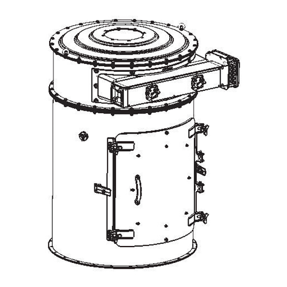
Page 61: Removing The Filter Elements Through The Maintenance Hatch Unavailable For Zone 21
WAMFLO FN200X ® 05.22 8.0 REPLACEMENT OF PARTS FIL.WAMFLO_FN200.EX.M.A7.0522.EN Issue: A7 8.4 Removing the filter elements through the maintenance hatch UNAVAILABLE FOR ZONE 21 Unscrew the hatch knobs. Open inspection hatch, by pulling from left to right the knob. If the operation is found to be difficult, hold both edges of the door with both hands and pull simultane- ously. - Page 62 WAMFLO FN200X ® 05.22 8.0 REPLACEMENT OF PARTS FIL.WAMFLO_FN200.EX.M.A7.0522.EN Issue: A7 Lower them enough to remove from the front by pulling upwards. Carry out cleaning operations as described in the catalogue (see previous pages). For assembly carry out the removal operations in reverse order.
-
Page 63: Replacing The Solenoid Valve
WAMFLO FN200X ® 05.22 8.0 REPLACEMENT OF PARTS FIL.WAMFLO_FN200.EX.M.A7.0522.EN Issue: A7 8.5 Replacing the solenoid valve Danger - Warning Set the filter in safety condition (see "Glossary and Terminology"). 1) Remove the coil (6) and the connector (7) after having removed the relative ring nuts; 2) Remove the hex screws and washers which secure the valve cover (3);... -
Page 64: Returning The Equipment (The Machine)
WAMFLO FN200X ® 05.22 8.0 REPLACEMENT OF PARTS FIL.WAMFLO_FN200.EX.M.A7.0522.EN Issue: A7 8.6 Returning the equipment (the machine) When returning the equipment (machine) use the original packaging if it has been preserved, otherwise fix the it on a pallet and cover it with nylon shrink-wrap, to protect it as best as possible from impact during transport. In any event, make sure there is no residue material inside the equipment (machine). -
Page 65: Information Regarding Faults
WAMFLO FN200X ® 05.22 9.0 INFORMATION REGARDING FAULTS FIL.WAMFLO_FN200.EX.M.A7.0522.EN Issue: A7 9.1 Trouble-shooting Minor problems can be solved without consulting a specialist. The following Table contains a list of the most common problems, the possible causes and possible remedies. For particularly difficult actions which are not mentioned in the Table, contact the Manufacturer’s Customer Service Department. - Page 66 WAMFLO FN200X ® 05.22 9.0 INFORMATION REGARDING FAULTS FIL.WAMFLO_FN200.EX.M.A7.0522.EN Issue: A7 Suction fan FAULT PROBABLE CAUSE POSSIBLE REMEDY Tubes clogged and/or suction points Clean tubes and hoods, check posi- clogged. tion of valves. Check supply voltage and check terminal connections of motor; check Rotation speeds too low.
- Page 67 WAMFLO FN200X ® 05.22 9.0 INFORMATION REGARDING FAULTS FIL.WAMFLO_FN200.EX.M.A7.0522.EN Issue: A7 FAULT PROBABLE CAUSE POSSIBLE REMEDY Rotation speed so high as to require a Replacement of motor and pulleys power greater than that installed. and/or redefine the system. Power absorption higher than rating Air density greater than the one envis- See above.
- Page 68 WAMFLO FN200X ® 05.22 9.0 INFORMATION REGARDING FAULTS FIL.WAMFLO_FN200.EX.M.A7.0522.EN Issue: A7 Electronic board FAULT SOLUTION A) If the MS green LED does not get lit. 1) Check the power supply on terminal S1. 2) Check the performance of the fuse (for replacement, use a fuse of the same type and having the same value) Not working If the MS green LED get lit.
-
Page 69: Check-List In Case Of Fault
WAMFLO FN200X ® 05.22 9.0 INFORMATION REGARDING FAULTS FIL.WAMFLO_FN200.EX.M.A7.0522.EN Issue: A7 9.2 Check-list in case of fault If you have been unable to solve the problem on the equipment (machine) even after having carried out the operations suggested in paragraph “Trouble-shooting” please contact the plant technician/installer/or the Manufacturer. - Page 70 WAMFLO FN200X ® 05.22 9.0 INFORMATION REGARDING FAULTS FIL.WAMFLO_FN200.EX.M.A7.0522.EN Issue: A7 4) Checking the dust a) Description of the material b) Density? (kg/dm3) c) Particle size? (µm/m) d) Moisture? (%) e) Flowability? f) Compressibility? g) Abrasiveness?
-
Page 71: Technical Data
WAMFLO FN200X ® 05.22 10.0 TECHNICAL DATA FIL.WAMFLO_FN200.EX.M.A7.0522.EN Issue: A7 10.1 Dimensions and weights of the standard filter FIRST PRIMO MAINTENANCE HOLE FORO VIEW A-A VISTA A-A FIRST PRIMO HOLE FORO Filter Modules Filtering elements Weight CODE surface ØL ØM ØN α... - Page 72 WAMFLO FN200X ® 05.22 10.0 TECHNICAL DATA FIL.WAMFLO_FN200.EX.M.A7.0522.EN Issue: A7 Bags removable from the front FIRST PRIMO HOLE only for Ø 1000 FORO VIEW A-A VISTA A-A FIRST PRIMO HOLE FORO Filter Modules elements Filtering Weight surface CODE (kg) Length No.
- Page 73 WAMFLO FN200X ® 05.22 10.0 TECHNICAL DATA FIL.WAMFLO_FN200.EX.M.A7.0522.EN Issue: A7 • • • • • • • STANDARD LOWER BODY INTERMEDIATE BODY HATCH UPPER BODY Thickness Finishing Thickness Finishing Thickness Finishing Thickness Finishing Polishing None 1360 1.5 mm 2 mm 120-180 (4/4/IV*) 1840...
-
Page 74: Filter Elements
(cartridge and POLYPLEAT ). The latter solution ensures optimum use of the ® space available, but is incompatible with certain types of applications. For further details consult the WAM ® technical-sales department. The Venturi system, used in the WAMFLO... -
Page 75: Filter Media
10.3 Filter media To meet the applications requirements in different industrial sectors, for all filter elements it is possible to use different types of filtering media. The WAM filtering media are strictly certified by the Institute for the Work- ®... -
Page 76: Timers The Pneumatic Timer Unavailable For Zone 21
Fig. 1 Electronic timer (fig.1) The WAM electronic control panel can be powered with a 24V - 260V AC/DC, 50/60 Hz supply and installed ®... -
Page 77: Cleaning System
WAMFLO FN200X ® 05.22 10.0 TECHNICAL DATA FIL.WAMFLO_FN200.EX.M.A7.0522.EN Issue: A7 10.5 Cleaning system For WAMFLO filters, the filter elements cleaning system can be selected in order phase (box 3 of modular ® key): J - reverse compressed air jet Reverse compressed air jet •... - Page 78 WAMFLO FN200X ® 05.22 10.0 TECHNICAL DATA FIL.WAMFLO_FN200.EX.M.A7.0522.EN Issue: A7 Mechanical vibrated system cleaning system Blowing unit The cleaning system consists of: - Three-phase asynchronous electric vibrator; - The junction box is provided with strip connectors for the fitting of the vibrator and of the exhaust fan (if installed).
-
Page 79: Options: Materials And Finishing
WAMFLO FN200X ® 05.22 10.0 TECHNICAL DATA FIL.WAMFLO_FN200.EX.M.A7.0522.EN Issue: A7 10.6 Options: materials and finishing • • • • • • • • • • • • • ITEM DESCRIPTION MATERIAL THICKNESS FINISHING Cover SS 316 1 mm SS 304 2 mm 2B (UNI EN 10088-2/4 1997) Filter body... -
Page 80: Accessories
WAMFLO FN200X ® 05.22 10.0 TECHNICAL DATA FIL.WAMFLO_FN200.EX.M.A7.0522.EN Issue: A7 10.7 Accessories Materials and finishings Sez.A-A • • xt. = 787 • ITEM DESCRIPTION MATERIAL THICKNESS FINISHING KWP01 Rain cover ---- Carbon steel 2 mm Powder painted RAL7001 Filter flange SS 304 2 mm 2B (UNI EN 10088-2/4 1997) - Page 81 WAMFLO FN200X ® 05.22 10.0 TECHNICAL DATA FIL.WAMFLO_FN200.EX.M.A7.0522.EN Issue: A7 Choke valve with silencer FL 1 VPA_T ØC ØD VPA + Diameter C Diameter D Weight S Silencer [mm] [mm] [mm] (Interno) [mm] (Esterno) [kg] VPAAS VPABS 11,5 VPACS VPADS FAN FLANGE FAN TYPE N°...
- Page 82 WAMFLO FN200X ® 05.22 10.0 TECHNICAL DATA FIL.WAMFLO_FN200.EX.M.A7.0522.EN Issue: A7 Silencer FL 1 FL 2 ØF ØE Diameter F Diameter F Weight S Silencer [mm] [mm] [mm] (Interno) [mm] (Esterno) [kg] SLA00 SLB00 SLC00 SLD00 15,5 FAN FLANGE FAN TYPE N°...
-
Page 83: Aattachments
Strada degli Schiocchi, 12 - I-41124 Modena - Italy under its own responsibility declares that: WAMFLO FOOD FN200X (code: FN200X…) DECLARATION OF INCORPORATION OF PARTLY COMPLETED MACHINERY Annex II B 2006/42/CE Directive of the European Parliament and the Council of 17 May 2006 on machinery comply with the RES Directive 2006/42/EC 1.1.1... - Page 84 Strada degli Schiocchi, 12 - I-41124 Modena - Italy under its own responsibility declares that: WAMFLO FOOD FN200X (code: FN200X…) DECLARATION OF INCORPORATION OF PARTLY COMPLETED MACHINERY Annex II B 2006/42/CE Directive of the European Parliament and the Council of 17 May 2006 on machinery comply with the RES Directive 2006/42/EC 1.1.1...
- Page 85 WAMFLO FN200X 05.22 ® A ATTACHMENTS FIL.WAMFLO_FN200.EX.M.A7.0522.EN Issue: A7 The manufacturer: WAMGROUP S.p.A. located in Strada degli Schiocchi, 12 - I-41100 Modena (Mo) - Italy under its own responsibility declares that: in the following dust collectors: WAMFLO FOOD FN200, WAMFLO FOOD FN200X (ATEX zone 22 and zone 21) ®...
Need help?
Do you have a question about the WAMFLO FOOD FN200X and is the answer not in the manual?
Questions and answers