Table of Contents
Advertisement
2
Jamieson Equipment Company | 5314 Palmero Court | Buford, GA 30518 | 800.875.0280 | sales@jamiesonequipment.com
EN
SILO VENTING
DUST COLLECTORS
INSTALLATION
OPERATION AND
MAINTENANCE
Manual No. FIL.100.--.M.EN
Latest Update: June 2012
ORIGINAL INSTRUCTIONS IN ENGLISH
SILOTOP
R03 Series
Issue: A2
®
Advertisement
Table of Contents

Related Manuals for WAM SILOTOP R03


Summary of Contents for WAM SILOTOP R03
- Page 1 SILOTOP ® R03 Series SILO VENTING DUST COLLECTORS INSTALLATION OPERATION AND MAINTENANCE Manual No. FIL.100.--.M.EN Issue: A2 Latest Update: June 2012 ORIGINAL INSTRUCTIONS IN ENGLISH Jamieson Equipment Company | 5314 Palmero Court | Buford, GA 30518 | 800.875.0280 | sales@jamiesonequipment.com...
- Page 2 All the products described in this catalogue are manufactured according to WAMGROUP S.p.A. Quality System procedures. The Company’s Quality System, certified in July 1994 according to International Standards UNI EN ISO 9002 and extended to the latest release of UNI EN ISO 9001, ensures that the entire production process, starting from the processing of the order to the technical service after delivery, is carried out in a controlled manner that guarantees the quality standard of the product.
-
Page 3: Table Of Contents
SILOTOP R03 06.12 INDEX FIL.100.--.M.EN Issue: A2 SUMMARY 1.0 GENERAL INFORMATION ........................1 1.1 Scope of the Manual .........................1 1.2 Symbols ............................2 1.3 Glossary and terminology .........................4 1.4 Manufacturer’s data and identification of equipment ................. 5 1.5 Request for assistance ........................6 1.6 Warranty ............................6... - Page 4 SILOTOP R03 06.12 INDEX FIL.100.--.M.EN Issue: A2 6.0 INFORMATION REGARDING USE .......................42 6.1 Production start-up ..........................42 6.2 Equipment shutdown at the end of the work cycle ................42 6.3 Long shutdown of the equipment ....................43 6.4 Reuse ..............................43 7.0 INFORMATION REGARDING MAINTENANCE ..................44 7.1 Cleaning the equipment (the machine) ...................44...
-
Page 5: General Information
SILOTOP R03 06.12 1.0 GENERAL INFORMATION FIL.100.--.M.EN Issue: A2 1.1 Scope of the Manual This Manual has been prepared by the Manufacturer to provide the operating technical information for instal- lation, operation and maintenance of the equipment concerned. The Manual, which is an integral part of the equipment concerned, must be preserved throughout the life of the equipment in a known easily accessible place, available for consultation whenever required. -
Page 6: Symbols
SILOTOP R03 06.12 1.0 GENERAL INFORMATION FIL.100.--.M.EN Issue: A2 1.2 Symbols To highlight certain parts of the text, for purposes of safety, or to indicate important information, certain symbols are used, the meaning of which is described below. It is important to comply with and scrupulously follow the information highlighted by the symbols. -
Page 7: Fil.100.--.M.en Issue: A2
SILOTOP R03 06.12 1.0 GENERAL INFORMATION FIL.100.--.M.EN Issue: A2 List of safety and information symbols Symbol Symbol description representation Danger sign: indicates danger of electric shock caused by the presence of powered components inside the junction box or control panel. -
Page 8: Glossary And Terminology
SILOTOP R03 06.12 1.0 GENERAL INFORMATION FIL.100.--.M.EN Issue: A2 1.3 Glossary and terminology Operator: person appropriately trained and authorized by the Production Manager for setting up the equip- ment concerned and carrying out routine maintenance. Installer: organization with specialized technicians and appropriate equipment for carrying out risk-free instal- lation and extraordinary maintenance. -
Page 9: Manufacturer's Data And Identification Of Equipment
SILOTOP R03 06.12 1.0 GENERAL INFORMATION FIL.100.--.M.EN Issue: A2 1.4 Manufacturer’s data and identification of equipment Important Do not change the data on the identification plate. Keep the ID plates clean, intact and legible as regards the data they contain. -
Page 10: Request For Assistance
SILOTOP R03 06.12 1.0 GENERAL INFORMATION FIL.100.--.M.EN Issue: A2 1.5 Request for assistance For all technical assistance, contact the Manufacturer’s service network. For all requests, provide the equipment identification data, the type of problem encountered and all other infor- mation which could be useful for identifying the problem. -
Page 11: Information Regarding Safety
SILOTOP R03 06.12 2.0 INFORMATION REGARDING SAFETY FIL.100.--.M.EN Issue: A2 2.1 General safety prescriptions Read the Instruction Manual carefully and strictly follow the instructions it includes, especially those regarding safety. Most accidents at the workplace are caused by negligence, failure to follow the most elementary safety regulations and incorrect or improper use of tools and equipment. -
Page 12: Safety Prescriptions For Installation
SILOTOP R03 06.12 2.0 INFORMATION REGARDING SAFETY FIL.100.--.M.EN Issue: A2 2.3 Safety prescriptions for installation Before starting with installation, a “Safety Plan” must be implemented to safeguard the personnel di- rectly involved and those who carry out operations in the surrounding area. -
Page 13: Fil.100.--.M.en Issue: A2
SILOTOP R03 06.12 2.0 INFORMATION REGARDING SAFETY FIL.100.--.M.EN Issue: A2 Apart from invalidation of the warranty, the Manufacturer declines all responsibility for damage to objects and harm to persons deriving from the use of non-original spare parts or due to modifications made during repairs without express written authorization. -
Page 14: Technical Information
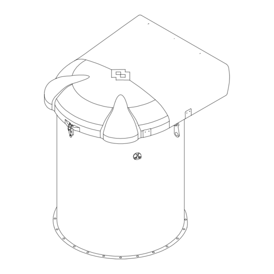
SILOTOP R03 06.12 3.0 TECHNICAL INFORMATION FIL.100.--.M.EN Issue: A2 3.1 General description of the equipment SILOTOP is a cylindrically shaped dust collector for venting of pneumatically filled silos. ® The stainless steel body contains vertically mounted POLYPLEAT filter elements. The air jet cleaning system ®... -
Page 15: Operating Principle
SILOTOP R03 06.12 3.0 TECHNICAL INFORMATION FIL.100.--.M.EN Issue: A2 3.3 Operating principle The dirty air enter the dust collector body (1) where dust is separated by the filter elements (8). Dust drops back into the silo after an automatic reverse air jet cleaning system (3+4+5) has removed it from the filter elements. -
Page 16: Noise Level
SILOTOP R03 06.12 3.0 TECHNICAL INFORMATION FIL.100.--.M.EN Issue: A2 3.6 Noise level The noise level of the SILOTOP R03 series dust collector does not exceed the limit of the directive 86/188/ ® CEE and 89/392/CEE. The measured equivalent continuous A-weighted sound pressure level LAeq is 70.0 dB(A). -
Page 17: Overall Dimensions And Technical Features
SILOTOP R03 06.12 3.0 TECHNICAL INFORMATION FIL.100.--.M.EN Issue: A2 3.8 Overall dimensions and technical features For an exact identification of the equipment concerned, see the identification plate. The shipping documents show the Serial number and identification codes. The information regarding the technical features of the equipment is given in Chapter 10. -
Page 18: Safety Devices
SILOTOP R03 06.12 3.0 TECHNICAL INFORMATION FIL.100.--.M.EN Issue: A2 3.10 Safety devices Access to the inspection hatches is not necessary while using the equipment concerned. Their use represents extraordinary use as they were provided for removing foreign bodies and accumulated material from the equip- ment or for extraordinary maintenance operations. -
Page 19: Fil.100.--.M.en Issue: A2
SILOTOP R03 06.12 3.0 TECHNICAL INFORMATION FIL.100.--.M.EN Issue: A2 In certain dust handling operations, where harmful substances are present, the operator concerned with the routine or extraordinary operations must wear suitable personal protection equipment as indicated on the no- tices present. -
Page 20: Fil.100.--.M.en Issue: A2
SILOTOP R03 06.12 3.0 TECHNICAL INFORMATION FIL.100.--.M.EN Issue: A2 Other hazards OPERATING LEGAL RESIDUAL HAZARD DAMAGE CAUSE SAFETY MEASURES INSTRUC- REFERENCE RISKS TIONS Electricity Electric All interventions on the elec- shock junction tric parts have to be carried caused box was... -
Page 21: Information Regarding Handling And Transport
SILOTOP R03 06.12 4.0 INFORMATION REGARDING HANDLING AND TRANSPORT FIL.100.--.M.EN Issue: A2 4.1 Type of packaging The filter is supplied on a pallet and protected with a wooden crate. WAM s.p.a. CAVEZZO ØB Weight with wooden crate ø B (kg) -
Page 22: Reception Of Goods
SILOTOP R03 06.12 4.0 INFORMATION REGARDING HANDLING AND TRANSPORT FIL.100.--.M.EN Issue: A2 4.2 Reception of goods On receiving the goods, ensure that the type and quantity correspond to the data present on the acknowledge- ment of order. Possible damage has to be immediately communicated in writing in the space provided to this purpose in the waybill. -
Page 23: Fil.100.--.M.en Issue: A2
SILOTOP R03 06.12 4.0 INFORMATION REGARDING HANDLING AND TRANSPORT FIL.100.--.M.EN Issue: A2 Lifting the dust collector The dust collector should only be handled and lifted using the eye-bolts provided. Use lifting devices suitable to the weight and dimensions of the dust collector and to the lifting distances concerned. Connect the dust col- lector to the lifting device using shackle and safety hooks;... -
Page 24: Installation And Fixing
SILOTOP R03 06.12 5.0 INSTALLATION AND FIXING FIL.100.--.M.EN Issue: A2 5.1 Recommendations for installation Danger - Warning The installation operations have to be carried out by a technician specialized in such activities. Provide appropriate safety measures and use suitable equipment to prevent risk of work accident to persons involved in the operations and to those nearby. -
Page 25: Fil.100.--.M.en Issue: A2
SILOTOP R03 06.12 5.0 INSTALLATION AND FIXING FIL.100.--.M.EN Issue: A2 The equipment supplied is provided with perimeter gasket to be inserted between the dust collector and the bottom ring. Tighten the bolts by applying a tighten torque of 10 Nm. -
Page 26: Positioning The Dust Collector Flange
SILOTOP R03 06.12 5.0 INSTALLATION AND FIXING FIL.100.--.M.EN Issue: A2 5.2 Positioning the dust collector flange “A” - Spot welding View from “A” - Checking the circularity - Complete the welding Jamieson Equipment Company | 5314 Palmero Court | Buford, GA 30518 | 800.875.0280 | sales@jamiesonequipment.com... -
Page 27: Installation - Emissions Sampling Kit
SILOTOP R03 06.12 5.0 INSTALLATION AND FIXING FIL.100.--.M.EN Issue: A2 5.3 Installation - Emissions sampling kit Open the cover Close the two front openings under the cover using the 2 shaped metal sheets Fit the blind flange to close one of the rear air outlets... -
Page 28: Fil.100.--.M.en Issue: A2
Close the other rear air outlet with the remaining flange with the cylindrical stub pipe Assemble the vertical tube for fumes extraction (NOT SUPPLIED BY WAM ) by connection to the cylindrical stub pipe shown in the previous Figure ®... -
Page 29: Electrical Connection
SILOTOP R03 06.12 5.0 INSTALLATION AND FIXING FIL.100.--.M.EN Issue: A2 5.4 Electrical connections Danger - Warning Connection to the mains has to be carried out by an electrician. Provide mains supply to the equipment concerned according to the compliant current legislation and take into consideration the safety measures required by the installation environment and the envis- aged operating conditions. -
Page 30: Fil.100.--.M.en Issue: A2
SILOTOP R03 06.12 5.0 INSTALLATION AND FIXING FIL.100.--.M.EN Issue: A2 Electronic control panel connection 1) POWER SUPPLY VOLTAGE - Works with all the supply voltages from 24V to 260V either in AC or in DC. 2) SUPPLY VOLTAGE AUTO-RECOGNITION - The electronic panel automatically recognises the voltage ap- plied, therefore no settings are necessary for normal operation. -
Page 31: Fil.100.--.M.en Issue: A2
SILOTOP R03 06.12 5.0 INSTALLATION AND FIXING FIL.100.--.M.EN Issue: A2 E.V. OUTPUT CONNECTIONS FOR OUTPUT EXPANSION ∆P DISPLAY ∆P SENSOR WORKING INDICATORS TIME SETTING CONNECTIONS MAINS SUPPLY 3, 4, 5, 6: NO VOLTAGE TO BE CONNECTED The picture shows the MDPE module (optional) -
Page 32: Wiring Diagram
SILOTOP R03 06.12 5.0 INSTALLATION AND FIXING FIL.100.--.M.EN Issue: A2 5.5 Wiring diagram WITHOUT MOTOR Board switch Jamieson Equipment Company | 5314 Palmero Court | Buford, GA 30518 | 800.875.0280 | sales@jamiesonequipment.com... -
Page 33: Timers Setting
SILOTOP R03 06.12 5.0 INSTALLATION AND FIXING FIL.100.--.M.EN Issue: A2 5.6 Timers setting Pause time The preset pause time can be modified by acting on the microswitch provided for the purpose in the following way: The picture shows the MDPE module... - Page 34 SILOTOP R03 06.12 5.0 INSTALLATION AND FIXING FIL.100.--.M.EN Issue: A2 Work time The preset work time can be modified by acting on the microswitch provided for the purpose in the following way: The picture shows the MDPE module MICROSWITCH 2...
-
Page 35: Electronic Control Panel: Mdpe Setting
SILOTOP R03 06.12 5.0 INSTALLATION AND FIXING FIL.100.--.M.EN Issue: A2 5.7 Electronic control panel: MDPE setting Operating principle When connected electrically and mechanically to the control panel, the MDPE reads the pressure differential value between the 2 inputs of the transducer and displays it in millimetres of water column on a 3-digit display. -
Page 36: Fil.100.--.M.en Issue: A2
SILOTOP R03 06.12 5.0 INSTALLATION AND FIXING FIL.100.--.M.EN Issue: A2 The operating time (TIME) can be displayed by pressing P3 and the pause time (PAUSE) can be displayed by pressing P1 and P2. In the diagram bellow is indicated the combination of keys to be pressed to proceed to the next stages. -
Page 37: Fil.100.--.M.en Issue: A2
SILOTOP R03 06.12 5.0 INSTALLATION AND FIXING FIL.100.--.M.EN Issue: A2 Programming mode The programming procedure is activated by pressing P2 and P3 (ENTER) simultaneously. On pressing the keys the LH digit on the display will show an identification number (from 1 to 8) relative to the parameter being examined (see table), while the two remaining ones or just the last one, to the RH, indicates the value selected for that parameter. -
Page 38: Fil.100.--.M.en Issue: A2
SILOTOP R03 06.12 5.0 INSTALLATION AND FIXING FIL.100.--.M.EN Issue: A2 PROGRAMMING The display shows the flashing parameter to be set (digit 1) and its value (digit 2 and 3) NORMAL NORMAL OPERATION OPERATION (programming end) (programming end) Return to previous... - Page 39 SILOTOP R03 06.12 5.0 INSTALLATION AND FIXING FIL.100.--.M.EN Issue: A2 On entering the programming mode eight values of the first digit can be selected. Each of these represents a different parameter. The description of the function related to each parameter is given below.
-
Page 40: Fil.100.--.M.en Issue: A2
SILOTOP R03 06.12 5.0 INSTALLATION AND FIXING FIL.100.--.M.EN Issue: A2 a) Make sure there is no air flow through the filter. b) Disconnect both hose pipes from the outside of the controller board casing (part A). c) Enter module settings mode of field 7 of the MDPE and set the value to 1. -
Page 41: Fil.100.--.M.en Issue: A2
SILOTOP R03 06.12 5.0 INSTALLATION AND FIXING FIL.100.--.M.EN Issue: A2 DIGIT DIGIT DIGIT PARAMETER FUNCTION STATUS MDPE activate and deactivate the control board and so the cleaning system MDPE OPERATING MODE MDPE just provide the pressure value reading. Preset value 10 mm H... -
Page 42: Pneumatic Connections
SILOTOP R03 06.12 5.0 INSTALLATION AND FIXING FIL.100.--.M.EN Issue: A2 5.8 Pneumatic connections Compressed air requirements The operation of the filter requires permanent connection to a compressed air circuit. The compressed air must 1) Clean - Free of waste which could damage the filter solenoid valves 2) De-humidified - The filter tank is provided with a condensation drainage cap. -
Page 43: Fil.100.--.M.en Issue: A2
SILOTOP R03 06.12 5.0 INSTALLATION AND FIXING FIL.100.--.M.EN Issue: A2 AIR OUTLET AIR INLET CODE DESCRIPTION MANUAL BALL VALVE (NOT SUPPLIED BY WAM ® RELIEF VALVE (NOT SUPPLIED BY WAM ® TANK 1” RAPID DISCHARGE VALVE COIL AIR OUTLET CONDENSATION DRAINAGE... -
Page 44: Fil.100.--.M.en Issue: A2
SILOTOP R03 06.12 5.0 INSTALLATION AND FIXING FIL.100.--.M.EN Issue: A2 The compressed air coupling on the filter is achieved by means of a push-in fitting (for 12 mm pipe). The installer must fix the compressed air hose pipes correctly and provide the due protections against sudden detachment of the pipes. -
Page 45: Inspection
SILOTOP R03 06.12 5.0 INSTALLATION AND FIXING FIL.100.--.M.EN Issue: A2 5.9 Inspection Important When installation is complete, authorized personnel must carry out a general test to ensure that the safety conditions have been completely satisfied. The authorized personnel must also check: - that no tools or other material have been forgotten inside the filter;... -
Page 46: Information Regarding Use
SILOTOP R03 06.12 6.0 INFORMATION REGARDING USE FIL.100.--.M.EN Issue: A2 6.1 Production start-up Before starting up the filter, the operator in charge and authorized for the production must ensure that the safety devices installed are present, in working order and that the operating conditions are respected (hatches closed, inlet and outlet). -
Page 47: Long Shutdown Of The Equipment
SILOTOP R03 06.12 6.0 INFORMATION REGARDING USE FIL.100.--.M.EN Issue: A2 6.3 Long shutdown of the equipment When the filter remains unused for long periods, proceed as described below. 1) Avoid damp and salty enviroments during equipment shutdowns. 2) Place the equipment on wooden pallets and store it protected from inclement weather conditions. -
Page 48: Information Regarding Maintenance
SILOTOP R03 06.12 7.0 INFORMATION REGARDING MAINTENANCE FIL.100.--.M.EN Issue: A2 Danger - Warning Before carrying out any maintenance activity, activate all the safety devices to ensure the safety of the persons involved in the operations and those near by. Set the equipment concerned in safety condition (see 2.0 Information regarding safety). -
Page 49: Filter Element Cleaning
SILOTOP R03 06.12 7.0 INFORMATION REGARDING MAINTENANCE FIL.100.--.M.EN Issue: A2 7.2 Filter element cleaning POLYPLEAT ® The filter elements are made of highly resistant non-woven spun-bonded material which allows regeneration provided that a correct cleaning is carried out. Cleaning can be done using a common vacuum cleaner or non-metallic brushes ensuring that the filter surface is not damaged. -
Page 50: Replacement Of Parts
SILOTOP R03 06.12 8.0 REPLACEMENT OF PARTS FIL.100.--.M.EN Issue: A2 8.1 Safety recommendations for replacement Danger - Warning The replacement operations must be carried out by a specialist authorized technician with specific skills in the sector concerned (mechanical, electrical etc). - Page 51 SILOTOP R03 06.12 8.0 REPLACEMENT OF PARTS FIL.100.--.M.EN Issue: A2 OPEN THE FILTER COVER Remove the padlock. Open the snap lock. Jamieson Equipment Company | 5314 Palmero Court | Buford, GA 30518 | 800.875.0280 | sales@jamiesonequipment.com...
- Page 52 SILOTOP R03 06.12 8.0 REPLACEMENT OF PARTS FIL.100.--.M.EN Issue: A2 Open completely the cover using the handle. Slacken the nuts of the clamps. Shift the clamps to release the filter elements. Pull out the filter element without damaging it. For reassembly, repeat the above operations in reverse.
-
Page 53: Replacing Solenoid Valve
SILOTOP R03 06.12 8.0 REPLACEMENT OF PARTS FIL.100.--.M.EN Issue: A2 8.3 Replacing solenoid valve Danger - Warning Set the filter in safety condition (see glossary and terminology). 1) Remove coil (6) and connector (7) after removing the relative ring nut;... -
Page 54: Returning The Equipment (The Machine)
SILOTOP R03 06.12 8.0 REPLACEMENT OF PARTS FIL.100.--.M.EN Issue: A2 8.4 Returning the equipment (the machine) When returning the equipment (machine) use the original packaging if it has been preserved, otherwise fix the it on a pallet and cover it with nylon shrink-wrap, to protect it as best as possible from impact during transport. -
Page 55: Information Regarding Faults
SILOTOP R03 06.12 9.0 INFORMATION REGARDING FAULTS FIL.100.--.M.EN Issue: A2 9.1 Trouble-shooting Minor problems can be solved without consulting a specialist. The following Table contains a list of the most common problems, the possible causes and possible remedies. For particularly difficult actions which are not mentioned in the Table, contact the Manufacturer’s Customer Service Department. - Page 56 SILOTOP R03 06.12 9.0 INFORMATION REGARDING FAULTS FIL.100.--.M.EN Issue: A2 Electronic control panel Problem Solution A) if the MS green LED does not flash 1) Check the power supply on terminal S1 2) Check the performance of the fuse (for replacement, use a fuse of the...
-
Page 57: Check-List In Case Of Fault
SILOTOP R03 06.12 9.0 INFORMATION REGARDING FAULTS FIL.100.--.M.EN Issue: A2 9.2 Check-list in case of fault If you have been unable to solve the problem on the equipment (machine) even after having carried out the operations suggested in paragraph “Trouble-shooting” please contact the plant technician/installer/or the Manufacturer. -
Page 58: Technical Data
SILOTOP R03 06.12 10 TECHNICAL DATA FIL.100.--.M.EN Issue: A2 10.1 Dimensions and weights VIEW A-A *Only for maintenance No. of filter elements Filter surface Weight No. of solenoid valves Code (kg) SILOTOP ® 24.5 Jamieson Equipment Company | 5314 Palmero Court | Buford, GA 30518 | 800.875.0280 | sales@jamiesonequipment.com... -
Page 59: Filter Elements
SILOTOP R03 06.12 10 TECHNICAL DATA FIL.100.--.M.EN Issue: A2 10.2 Filter elements The SILOTOP R03 Venting Filter is provided with seven POLYPLEAT filter elements. ® ® These elements are parallelepiped-shaped and the dimensions are as shown in the diagram above; the filter media is a non-woven pleated spunbonded material with B.I.A. -
Page 60: Cleaning System
SILOTOP R03 06.12 10 TECHNICAL DATA FIL.100.--.M.EN Issue: A2 10.3 Cleaning system SILOTOP filter elements are cleaned by a reverse compressed air jet cleaning system. It consists of: - Solenoid valves (1) fitted directly inside compressed air tank (2); - 304 stainless steel blowing pipe (3);... -
Page 61: Accessories - Bottom Ring
SILOTOP R03 06.12 10 TECHNICAL DATA FIL.100.--.M.EN Issue: A2 10.4 Accessories - Bottom ring Bottom ring Used to connect the filter to a hopper, silo etc. The ring is welded on the silo, hopper or cell and then bolted to the filter. -
Page 62: Accessories - Emissions Sampling Connection Kit
SILOTOP R03 06.12 10 TECHNICAL DATA FIL.100.--.M.EN Issue: A2 10.5 Accessories - Emissions sampling connection kit The emission sampling connection kit is used to convey all the air from the filter outlet into a single pipe. Code: KDE3 *NOT SUPPLIED BY WAM ®... - Page 63 FIL.100.--.M.EN Issue: A2 10.5 Accessories - Emissions sampling connection kit In case of plants with more filters, WAM suggests using a single tube to be shifted from one filter to another. ® After making the measurement, remove the tube and air closure plates.
-
Page 64: Aattachments
SILOTOP R03 06.12 A ATTACHMENTS FIL.100.--.M.EN Issue: A2 A1 Declaration of Incorporation The manufacturer: WAMGROUP S.p.A. located in Strada degli Schiocchi, 12 - I-41100 Modena (Mo) - Italy under its own responsibility declares that: SILOTOP R03 Series ® Declaration Of Incorporation Of Partly Completed Machinery Annex II B 2006/42/CE Directive...
Need help?
Do you have a question about the SILOTOP R03 and is the answer not in the manual?
Questions and answers