Table of Contents
Advertisement
Quick Links
ECT-SERIES
OPERATING INSTRUCTIO
OPERATING INSTRUCTIONS
Rev 1.2 (9/26/2022)
Heading
SILICON VALLEY HEADQUARTERS
1080 North 11th Street, San Jose, CA 95112 | Phone: (408) 292
North 11th Street, San Jose, CA 95112 | Phone: (408) 292-2214 | Fax: (408) 292-2733 | mountztorque.com
Page
2
3
5
7
7
11
16
18
21
23
25
31
37
39
40
40
41
41
42
43
44
45
46
46
47
48
50
52
53
54
57
1
Advertisement
Table of Contents

Related Manuals for Mountz ECT Series


Summary of Contents for Mountz ECT Series
-
Page 1: Table Of Contents
ECT-SERIES OPERATING INSTRUCTIO OPERATING INSTRUCTIONS Rev 1.2 (9/26/2022) Heading Page Layout Overview Controller System Start-up Process Controller Operation Screen Overview Controller Operation Screen Overview Parameter Menu Overview Fastening Settings Advanced Settings Multi Sequence Settings Model Settings Presets or Model Selection Screw Count Settings Controller Settings I/O settings... -
Page 2: Layout Overview
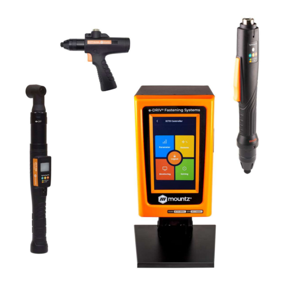
ECTD Controller ECTD-5000U and ECTD-5000E controllers is compatible with ECT-Series smart electric screwdrivers. Input (Electric): Input: AC120VC / AC230V, 50/60Hz 2.5A Output (Electric): DC38V 3.5A Fuse: 230V 25A Operating Environment: 0 ~ 40℃ / 15 ~ 80% RH (without dew) Bottom View Front Panel: 4.3”... -
Page 3: Controller System Start-Up Process
Controller System Start-up Process Before attempting to make any settings, it is essential to initialize the controller and electric screwdriver as a set, as the information stored within the controller during testing at the time of manufacture may not correlate with the screwdriver shipped with the system. This process should be used when first turning on the unit or after changing an electric screwdriver. - Page 4 Open driver model list Select screwdriver model in list Power reset is done automatically and controller is initialized with selected screwdriver factory parameters. Torque unit selection: If necessary change torque unit (changing torque unit will reset all parameters) same procedure as above Open torque unit list...
-
Page 5: Controller Operation Screen Overview
Controller Operation Screen Overview Menu Fastening Result OK/NG/Ready Monitoring Torque Torque Unit Preset (Model) # 1 - 15 Torque Target Speed Target / Monitoring Fastening Time Angle A1 / A2 Count (Target / Count) Monitoring Angle / Time Date & Time Operation screen is a default window when the controller power ON. - Page 6 Touch Screen field to move Main Menu Preset # or Model select Last count cancel Real time monitoring SILICON VALLEY HEADQUARTERS 1080 North 11th Street, San Jose, CA 95112 | Phone: (408) 292-2214 | Fax: (408) 292-2733 | mountztorque.com...
-
Page 7: Parameter Menu Overview
Parameter Menu Overview Fastening Settings Parameters listed on A and B pages for each Preset from 1 to 15 SILICON VALLEY HEADQUARTERS 1080 North 11th Street, San Jose, CA 95112 | Phone: (408) 292-2214 | Fax: (408) 292-2733 | mountztorque.com... - Page 8 Preset Selection Type Unit Range Initial Description Control type TC/AM: torque control / angle monitoring AC/TM: angle control / torque monitoring Target Torque Unit Range Initial set up in controller Tool range Description TC/AM: Target torque AC/TM: Max torque Torque Limit Unit Range Initial...
- Page 9 Target Angle Unit Range Initial degree 0 ~ 9999 Description Target angle in AC/TM mode Min Angle Unit Range Initial degree 0 ~ 9999 Description Minimum angle to be OK in TC/AM mode Max Angle Unit Range Initial degree 0 ~ 9999 Description Maximum angle to be OK in TC/AM...
- Page 10 Soft Start Unit Range Initial msec 0 ~ 300 Description Speed reach to the target in the setting time, Preset complement to acceleration controller parameter Seating Point Torque % Unit Range Initial 10 ~ 95 Description In TC/AM: % of Target torque Auto speed slow down to ramp-up speed for torque control In AC/TM: to be set with same torque value as Snug torque, in % of Max torque...
-
Page 11: Advanced Settings
Advanced Settings Parameters listed on A and B pages for each Preset from 1 to 15 SILICON VALLEY HEADQUARTERS 1080 North 11th Street, San Jose, CA 95112 | Phone: (408) 292-2214 | Fax: (408) 292-2733 | mountztorque.com... - Page 12 Advanced Functions: In this mode there are 4 extra functions can be set In this mode there are 4 extra functions can be set independently for each Preset. 1. Free Reverse Rotation 2. Engaging Torque Detection 3. Angle After Torque Up 4.
- Page 13 Engaging Torque Detection This setting is only possible when the screw engaging provides significantly higher torque than the previous free run. Speed Unit Range Initial Tool range Description Tool rotation speed Torque (%) Unit Range Initial 0 ~ 50 Description Engaging torque setting by percentage of target torque –...
- Page 14 Angle After Torque Up After tightening by torque control, it manages extra angle control in both forward and reverse directions. Speed Unit Range Initial Tool range Description Driver rotation speed Angle Unit Range Initial degree 0 ~ 15000 Description Rotation angle Direction Unit Range...
- Page 15 It is not the case in the chart (on prior page), but the tapping torque can be higher than the target torque (tapping in metal sheets, for example) Min Thread Torque Unit Range Initial set up in controller Tool range Description Torque level to start tapping monitoring Reach upward and higher than end torque parameter...
-
Page 16: Multi Sequence Settings
Multi Sequence Settings Toggle up and down between the number of steps Fastening Automation Workflows When there is a repetitive series of tightening tasks, manufacturers should implement a fastening automation workflow process. By creating a fastening automation workflow, the manufacturing process becomes streamlined and reduces human error risk. - Page 17 Command Description Data (range) No operation No use Fastening Tool start fastening process in forward rotation - Selected Preset Preset selection 1 to 15 is fill in Data field Loosening Tool start loosening process in reverse rotation Angle in 0.1 turn up to 999 Select preset# Select preset # (not mandatory ) Preset can be selected in data Preset selection 1 to 15...
-
Page 18: Model Settings
Model Settings They are 15 sequencing models of 20 steps with assignable tightening program batch counting and logical IO management. Model should be activated in controller parameters. The digital inputs for preset # select becomes model # select automatically. Each step can have one of the above commands with related setting value. - Page 19 Fastening setting: The fastening with counting number follows all settings and features in Screw Count menu except the number of screw. The spindle can be locked automatically in all steps except Fastening step, by selecting Enable on the menu Controller ‘Auto lock’ (model). Input/Output setting: IO port used in models should be unassigned (None) in IO settings Inputs port 9 to 15 are unassigned and dedicated to models Command details...
- Page 20 Bar code: receiving a barcode to go to next step If model barcode step data is set between 1 to 30: It can go next step by receiving only barcode data scanned in setting menu Barcode (step) If model barcode step data is set 0: It can go next step by receiving any barcode data Can be used to merged a part barcode with tightening results SILICON VALLEY HEADQUARTERS...
-
Page 21: Presets Or Model Selection
Presets or Model Selection To use Model mode must select the ON setting for it. There are 15 presets of program. Each preset contains the following parameters - Torque - Speed - verifying angles - soft start duration time - free speed tightening. Preset #1 Preset #15 Multi A,B... - Page 22 Parameter for Preset o program each presets, click Menu icon and select Parameter icon. Parameter menu require password to log in. The initial factory setting is “ 0 “ for password The password can be changed once log in. There are .875 address for each parameters. Parameters are grouped for each settings as below.
-
Page 23: Screw Count Settings
Screw Count Settings Screw count parameters are set for presets and models. Cycle Starts Signal select : Count start (IN) / end (OUT) No signal, auto start (Auto) - auto reset to total number after “0” Sensor or switch with one trigger pulse - Count starts with only trigger pulse. Counting is valid until complete or reset. - Page 24 Counting is set in Model with different values for each fastening step. Middle Count number: When the count number is reaches to the middle count number, count complete signal out become ON till the total count is completed. ‘Port count signal type’ setting is ignored on this features. ‘0’...
-
Page 25: Controller Settings
Controller Settings Toggle up and down between the number of controller screen views (1-5) Driver ID Unit Range Initial 1 ~ 99 Description EC ID used to identify Ethernet data communication. Driver model Unit Range Initial Screwdriver list Unknown Description Screwdriver model selection: controller will auto soft boot itself when driver model is changed Torque unit... - Page 26 Password Unit Range Initial 0 ~ 9999 Description Password to access controller menu Factory setting password is ‘0’ at the initial. Controller parameter initialize Unit Range Initial 0 to 9999 Description Key in ‘77’ and press enter button. Resets the parameters back to factory settings - screwdriver is paired to controller.
- Page 27 Controller Settings (continued) Forward run time Unit Range Initial 0 - 60 Description Run limit to forward rotation – It prevents the continuous running over the preset time. The driver stops automatically at the preset time and provides the pattern NG with error code Reverse run time limit Unit Range...
- Page 28 Error display reset time Unit Range Initial 0 ~ 10 Description Error display and reset after the below set time Value 0: manual reset with RESET button Fastening OK signal time Unit Range Initial 0 ~ 500 Description Signal output time setting longer than 150ms which is factory setting. Shorter time than factory setting doesn’t work.
- Page 29 Controller Settings (continued) Selection on panel Unit Range Initial OFF - ON Description OFF: disable touch screen ON : allow touch screen use Reverse lock (hand held only) Unit Range Initial OFF- ON Description YES will disable the reverse rotation switch on screwdriver. Trigger start (hand held only) Unit Range...
- Page 30 Preset # display when power on Unit Range Initial 1 ~ 15 Description Choice of initial preset selection on display when power on. RS232 select Unit Range Initial MODBUS - Barcode MODBUS Description RS232 Port use: for data report or barcode reader Please ensure that baud rate is set to correct value Comport baud rate setting Unit...
- Page 31 Controller Settings (continued) odel selection mode Unit Range Initial OFF - ON Description ON: model selection on operation screen OFF: Preset and MA/MB selection on operation screen Preset/Model selection on panel Unit Range Initial Preset - Model Preset Description Allow Model or Preset selection on operation screen Model start by bar code (model) Unit Range...
- Page 32 Model auto restart Unit Range Initial OFF - ON Description ON: model restart automatically after previous one is completed OFF: model must be manually restarted when a model is completed Crowfoot Unit Range Initial OFF - ON Description ON: activate crowfoot setting Crowfoot ratio Unit Range...
- Page 33 Controller Settings (continued) Led/light on time Unit Range Initial 0 ~ 30 Description Screwdriver LED lamp off timer (used only with pistol grip models) 0 = lamp off timer disable. SILICON VALLEY HEADQUARTERS 1080 North 11th Street, San Jose, CA 95112 | Phone: (408) 292-2214 | Fax: (408) 292-2733 | mountztorque.com...
-
Page 34: I/O Settings
I/O settings SILICON VALLEY HEADQUARTERS 1080 North 11th Street, San Jose, CA 95112 | Phone: (408) 292-2214 | Fax: (408) 292-2733 | mountztorque.com... - Page 35 Input Function Dialog F/L switch enable: Allow reverse by external input when F/L switch is locked by controller setting Absolute home bit/socket position Set origin: Create the absolute home position monitored by motor angle encoder. Move origin point: Bit socket position goes back to the home position. SILICON VALLEY HEADQUARTERS 1080 North 11th Street, San Jose, CA 95112 | Phone: (408) 292-2214 | Fax: (408) 292-2733 | mountztorque.com...
- Page 36 Output Function Dialog SILICON VALLEY HEADQUARTERS 1080 North 11th Street, San Jose, CA 95112 | Phone: (408) 292-2214 | Fax: (408) 292-2733 | mountztorque.com...
-
Page 37: 25P I/O Schematic
25P I/O Schematic The digital I/O provide the free assignment feature for 8 Inputs and 8 Outputs. The digital I/O provide the free assignment feature for 8 Inputs and 8 Outputs. Factory setting of I/O assignments are as following. Factory setting of I/O assignments are as following. To validate changing I/O, turn the power OFF and ON again To validate changing I/O, turn the power OFF and ON again I/O connections... - Page 38 Binary coding with 5 inputs to select preset # and Mode (identical for Model Input Preset # Torque select Torque select Torque select Torque select Multi sequence Multi A Multi B Binary coding with 3 outputs for error codes in 7 groups Error code Alarm 3 Alarm 2...
-
Page 39: Network Settings
Network Settings Mode Unit Range Initial STATIC - DHCP STATIC Description STATIC: IP address should be set manually on controller DHCP: if controller is connected to a LAN with a DHCP router IP address will automatically given by LAN router IP address Unit Range... -
Page 40: Monitoring Menu
Monitoring Menu To monitor fastening data and I/O status, click menu icon and select Monitoring icon. There are three(3) real-time monitoring menu and one error history. - Graph: torque, Angle, Speed and current - I/O: Input & output status - Network: RS-232 & Ethernet settings - Error: latest 8 error history Graph (Torque curve) monitoring Two channel data curve for Current, Torque, Angle, Speed... -
Page 41: I/O Status Monitoring
I/O Status Monitoring The I/O & tool operation signals are displayed when they are activated. The temperature of the motor is also displayed. Network Setting SILICON VALLEY HEADQUARTERS 1080 North 11th Street, San Jose, CA 95112 | Phone: (408) 292-2214 | Fax: (408) 292-2733 | mountztorque.com... -
Page 42: Remote Menu
Remote Menu Remote menu provides remote tool operation, auto customizing parameters to have highest cycle time and resets. Click menu icon and select Remote icon. Remote The tool and output signal can be operated remotely by clicking on "Loosening" or "Fastening" buttons. It is a useful feature to simulate the tools in automation integration. -
Page 43: Auto Customizing Parameters
Auto Customizing Parameters Simulation & modification window EC and ECT tool has the auto speed setting feature against torque setting to minimize over torque by speed shock. This auto speed is safe speed on the hard joint condition. On the real application, this setting can be changed manually. -
Page 44: Speed Torque
Speed Torque ① Select Preset # to modify parameter settings ② Select one of Soft & Hard joint condition when it is obviously clear or both together when it is not clear to be clarified, then click START ③ Apply screw tightening several times until there is no more parameter changing on the simulation &... -
Page 45: Backup / Restore / Power Reset / Factory Reset
Remote: Backup / Restore / Power Reset / Factory Reset Backup Parameter save to SD-Card. 20200530.csv Backup is saved on the SD-Card - PARAM folder. 20200610.csv Back up file name: yyyymmdd.csv Only one file per day (latest backup erase previous one) Restore Restore backup file from SD-Card. -
Page 46: General Settings Menu
General Settings Menu Date & Time To modify date, time and backlight brightness , click menu icon and select setting icon. Date and time System date and time can be modified. yyyy-mm-dd hh:mm:ss SILICON VALLEY HEADQUARTERS 1080 North 11th Street, San Jose, CA 95112 | Phone: (408) 292-2214 | Fax: (408) 292-2733 | mountztorque.com... -
Page 47: General Settings: Options
General Settings: Options LCD Brightness Unit Range Initial 1-100 Description Manual LCD backlight brightness adjustment Touch buzzer Unit Range Initial OFF - ON Description Touch screen sound deactivated or activated Language Unit Range Initial List English Description Choose in a list of 5 languages: English, German, French, Spanish and Czech –... -
Page 48: Barcode & Barcode Step
Barcode & Barcode Step Barcode data Preset # Model # 1 to 15 MA=16 MB=17 Barcode registration # (total 30) The barcode information can select the Preset or Model by the setting. In order to use barcode scanner, there are some parameters to be selected prior to the barcode setting. (Controller menu) R2232 Select: Modbus / Barcode RS232 baud rate: Select right one for the scanner - usually 9600 - Total number of barcode registration: up to 30... - Page 49 Barcode Step setting Only for barcode reading used in model barcode step. Only for barcode reading used in model barcode step. Dialog menu Identical to Barcode (refer previous page). (refer previous page). Barcode registration # (total 30) code registration # (total 30) Max 32 characters each Barcode registration: barcode model step step for setting up value.
-
Page 50: Storage (Sd Card)
Storage Check SD card information and available memory. Important: Format will delete all data saved on memory card. To avoid losing data please make a copy on a PC before. SD memory card specification SD card type Size Format Industrial grade Class 10 Max 32GB FAT32 SILICON VALLEY HEADQUARTERS... - Page 51 System creates the folders of YEAR, MONTH automatically. And it creates one file in CSV format with System creates the folders of YEAR, MONTH automatically. And it creates one file in CSV format with System creates the folders of YEAR, MONTH automatically. And it creates one file in CSV format with the file name of DATE.
-
Page 52: Firmware Upgrade
The last scanning data is recorded together with every fastening data The last scanning data is recorded together with every fastening data. Firmware Upgrade 1. Power off cotroller Remove the SD card for data saving and use the new SD card for firmware update only. Remove the SD card for data saving and use the new SD card for firmware update only. -
Page 53: Maintenance
General Settings: Maintenance Enter alarm interval This step will triggers a banner stating maintenance interval is needed. Enter a value for interval (bottom button section). SILICON VALLEY HEADQUARTERS 1080 North 11th Street, San Jose, CA 95112 | Phone: (408) 292-2214 | Fax: (408) 292-2733 | mountztorque.com... -
Page 54: Torque Calibration And Compensation
Torque Calibration and Compensation Torque calibration: It is the master calibration for whole torque range of the tool, saved in the tool memory. The F/R switch should be at Reverse position before writing the new value. The torque calibration could be utilized to change the electric screwdriver calibration. The screwdriver should be recalibrated if replacing the motor or gear mechanism. - Page 55 - Tool speed - Low pass filter of the torque meter Torque + 10% - 10% Range A periodical torque calibration is required to keep the accuracy of fastening quality. Torque compensation: Individual torque tuning on each preset. Saved in the controller. Torque compensation can be used when: The reading on the torque meter is variable according to the fastening condition on each...
- Page 56 Total adjustable range is +/- 20% ( 80% to 120% ) for 15 presets. Torque compensation value is stored in the controller memory, not the tool memory. Torque compensation can be utilized to characterize a tool to an application (fastening joint). Torque compensation Example ■...
-
Page 57: Error Codes
Error Codes System Errors Code Error message Description How to reset Reset and retry booting. If When the power of controller is ON, the AD offset error current offset is out of range. failed, repair is required Under voltage protection on SMPS power Under voltage supply circuit. - Page 58 Fastening errors Code Error message Description How to reset Run time limit (Forward) Over time limit on A260 Resetting A260 value Run time limit (Reverse) Over time limit on A261 Resetting A261 value Model setting error Failure in Model programming Resetting Model Model cancel The Model process is canceled...
- Page 59 Over temperature Overtemperature over 70°C Mountz Calibration and Repair Services Mountz Inc. features an experienced calibration and repair staff. Our trained Mountz Service Locations technicians can calibrate and repair most any tool. Mountz provides rapid Eastern Service Center service with quality that you can trust as we offer three state-of-the-art 19051 Underwood Rd.
- Page 60 SILICON VALLEY HEADQUARTERS 1080 North 11th Street, San Jose, CA 95112 | Phone: (408) 292-2214 | Fax: (408) 292-2733 | mountztorque.com...
Need help?
Do you have a question about the ECT Series and is the answer not in the manual?
Questions and answers