Racelogic MFD Touch Manual
Hide thumbs
Also See for MFD Touch:
- Quick start manual (3 pages) ,
- Quick start manual (2 pages) ,
- User manual (6 pages)
Table of Contents
Advertisement
Quick Links
MFD Touch User Manual
•
01 Getting Started – MFD Touch
•
02 Installing MFD Touch
•
03 Screen Layout - MFD Touch
•
04 Data Display - MFD Touch
•
MFD Touch - Analogue Gauge Screen
•
MFD Touch - Bar Graph Screen
•
MFD Touch - G-Ball Screen
•
MFD Touch - Numerical Screens
•
MFD Touch - Target Screen
•
05 Settings - MFD Touch
•
07 - MFD Touch Technical Properties
•
MFD Touch - EC Declaration of Conformity
•
MFD Touch - PIN OUTS
•
MFD Touch - Technical Specification
•
MFD Touch - Updating the Firmware
1
Advertisement
Table of Contents

Subscribe to Our Youtube Channel
Related Manuals for Racelogic MFD Touch


Summary of Contents for Racelogic MFD Touch
- Page 1 MFD Touch - Target Screen • 05 Settings - MFD Touch • 07 - MFD Touch Technical Properties • MFD Touch - EC Declaration of Conformity • MFD Touch - PIN OUTS • MFD Touch - Technical Specification • MFD Touch - Updating the Firmware...
-
Page 2: What Is In The Box
01 Getting Started – MFD Touch Registration Please register your MFD Touch unit so that Racelogic can continue to provide you with notification of the latest software releases, firmware upgrades and to offer technical support. Register your unit here. What is in the box? -
Page 3: Displayed Parameters
VBOX 3i RTK Antenna RTK Displayed Parameters Standard parameters used are from the standard Racelogic CAN output from the VBOX. Decel test parameters are commonly used in brake testing, the majority of which require the use of the VBOX Brake... -
Page 4: Can Parameters
CAN Parameters When you connect MFD Touch to a VBOX data logger (CAN data source is not available with VBOX Speed Sensors) and have configured the CAN channels you want to capture, the VBOX CAN button will become visible on the Select Data Source screen. - Page 5 Example of CAN channels available from an IMU04 For a CAN channel to be available for selection, it must be selected to log by the VBOX unit via the VBOX Setup software, and it must be compatible with the display element on MFD Touch. IMPORTANT If you configure the VBOX to log 32 or more CAN channels, you may witness some erroneous behaviour where selected CAN parameters change on the MFD Touch display.
-
Page 6: Left Side
02 Installing MFD Touch Connectors You can find more detailed connector information on the PIN OUTS page. Left Side SD Card The unit uses an SD card to save and load settings, save test results and update the firmware. You can find more information here. -
Page 7: Right Side
CAN Input The bottom MFD Touch Lemo port is for connecting CAN to the VBOX using the supplied RLCAB005-C cable. CAN Output is also available on this port by using an RLVBACS024 CAN splitter. You can find more information here. - Page 8 If you are using a wiring loom, you must identify and connect the connector labelled "CAN OUT + POWER" to the bottom port on the MFD Touch. If you need help identifying the connector, you can find the relevant cable drawing here.
- Page 9 Connection to VBOX 100 Hz Speed Sensor When connecting MFD Touch to a VBOX 100 Hz Speed Sensor, you must connect the cable labelled "CAN OUT" to the bottom port on the MFD Touch. If you are using a wiring loom, you must identify the CAN Out connector and connect it to the bottom port on the MFD Touch.
- Page 10 Power The MFD Touch display powers via the connection to the VBOX unit. On boot up, the MFD Touch displays a splash screen. As MFD Touch boots up quicker than the VBOX, it will display 'Waiting for VBOX' with a scrolling progress bar until the VBOX is fully booted up.
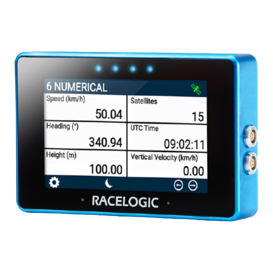
- Page 11 MFD Touch Splash Screen The first time the unit is booted up, it will display the screen "6 Numerical". After this, it will open the last used screen (if you have an SD card inserted). https://en.racelogic.support//Product_Info/Displays/MFD_Touch/MFD_Touch_User_Guide/02_-_MFD_Touch_Getting_Started...
- Page 12 It can also be secured using the ¼ 20 TPI UNC screw thread on the back of the unit. SD Card MFD Touch comes supplied with an 8 GB SDHC card that you can use to save and load settings, save test results and update the firmware.
- Page 13 SDHC cards (2 GB to 32 GB) Supplied or purchased SDHC cards are formatted in the FAT32 file format. This format is supported by MFD Touch. SDXC cards (64 GB and above) Purchased SDXC cards will be formatted in exFAT or NTFS file formats; these formats...
- Page 14 03 Screen Layout - MFD Touch As the name suggests, you can control the MFD Touch by using the capacitive touch screen. The top of the screen contains generally contains indicative status information. The centre of the screen contains mode/settings information that you can navigate by pressing the forward/ back buttons or by swiping left or right on the screen.
- Page 15 ◦ If you try to enable Write Results File when the unit cannot detect an SD card, the LEDs will flash red. KF Status If you enable IMU Integration in the connected VBOX 3i/3iS unit, MFD Touch will display the current IMU Kalman Filter status of that connected unit. The Kalman Filter Status Icon reflects the...
-
Page 16: Logging Status
RLCAB119 to the 25-way yet. D connector, is set to Racelogic CAN mode, and is running the latest release of the firmware. Flashing orange shows that the IMU is connected... -
Page 17: Gnss Status
• NO MEDIA AVAILABLE - VBOX 3i is unable to write to recordable media (i.e. corrupt card). If MFD Touch cannot detect a VBOX unit, it will display a 'NO CAN' message in this area. A Logging Status channel is also available for selection as a text parameter which will describe the current logging status of the connected VBOX. -
Page 18: Settings Button
You can use the Forward and Back arrow buttons to navigate through the different parameter screens. You can also swipe left or right on the screen. Confirm button Press the Confirm button at the bottom right of the screen to confirm your selection. https://en.racelogic.support//Product_Info/Displays/MFD_Touch/MFD_Touch_User_Guide/03_-_MFD_Touch_Screen_Layout... -
Page 19: Cancel Button
When you are in Night Mode, you can tap the Moon icon again to revert back to Day Mode. Note: Enabling Night Mode will reset any User Defined Text Colours. https://en.racelogic.support//Product_Info/Displays/MFD_Touch/MFD_Touch_User_Guide/03_-_MFD_Touch_Screen_Layout... - Page 20 'NO SD CARD' appear at the top of the screen. The LEDs will flash red 2 times and you will hear an audible error notification. A captured image is saved as a 1.5 MB bitmap image, https://en.racelogic.support//Product_Info/Displays/MFD_Touch/MFD_Touch_User_Guide/03_-_MFD_Touch_Screen_Layout...
- Page 21 90° to the original screen image, with the prefix 'screenshot'. IMPORTANT NEVER remove the SD card while you capture a screenshot with the unit, as it could cause it to crash! https://en.racelogic.support//Product_Info/Displays/MFD_Touch/MFD_Touch_User_Guide/03_-_MFD_Touch_Screen_Layout...
- Page 22 04 Data Display - MFD Touch Adding/Removing Screens MFD Touch can display up to 6 defined VBOX parameters. There are 8 different screens available to display a varying amount of parameters and gauges. You can add a maximum of 10 screens.
- Page 23 To add the screen, press the Confirm button on the bottom right of the screen to display the added screen. If you press the Cancel button on the bottom left of the screen you will return to the ADD/REMOVE screen without saving. https://en.racelogic.support//Product_Info/Displays/MFD_Touch/MFD_Touch_User_Guide/04_-_MFD_Touch_Data_Display...
-
Page 24: Display Screens
Forward or Back arrows on the sides of the screen. Press the Confirm button on the bottom right of the screen. Note: It is NOT possible to configure screens on an MFD Touch unit by using the VBOX Setup Software. Display Screens Once you have added screens, you can change the display by selecting the Forward or Back arrows on the bottom right of the screen or by swiping left or right. - Page 25 1 Numerical Screen 3 Numerical Screen 4 Numerical Screen 6 Numerical Screen Analogue Gauge Screen G-Ball Screen Target Screen Bar Graph Screen https://en.racelogic.support//Product_Info/Displays/MFD_Touch/MFD_Touch_User_Guide/04_-_MFD_Touch_Data_Display...
- Page 26 To save the new name, press the Confirm button on the bottom right of the screen. Press the Cancel button on the bottom left of the screen to return to the parameter screen without saving. If you have an SD card inserted in the unit, it will remember the value after each power cycle. https://en.racelogic.support//Product_Info/Displays/MFD_Touch/MFD_Touch_User_Guide/04_-_MFD_Touch_Data_Display...
- Page 27 Configure a Parameter You can configure each parameter by either pressing and holding or double-tapping the existing parameter area. This will open up the screen-specific menus. https://en.racelogic.support//Product_Info/Displays/MFD_Touch/MFD_Touch_User_Guide/04_-_MFD_Touch_Data_Display...
- Page 28 MFD Touch - Analogue Gauge Screen You can select the ANALOGUE GAUGE screen from the ADD/REMOVE screen. The Analogue Gauge screen contains an analogue needle gauge with 3 supporting numerical elements. The units used depends on what you have selected in Settings menu.
- Page 29 The analogue needle gauge element is located on the left-hand side of the screen. It provides a visual representation of a selected parameter (speed by default). You can configure the gauge by either pressing and holding or double-tapping on it. This will open up the ANALOGUE GAUGE SETTINGS menu. https://en.racelogic.support//Product_Info/Displays/MFD_Touch/MFD_Touch_User_Guide/04_-_MFD_Touch_Data_Display/ MFD_Touch_-_Analogue_Gauge_Screen...
- Page 30 You can return to the parameter screen by pressing the Exit button on the bottom left. Note: If you have an SD card inserted in the unit, it will remember the settings values after each power cycle. Data https://en.racelogic.support//Product_Info/Displays/MFD_Touch/MFD_Touch_User_Guide/04_-_MFD_Touch_Data_Display/ MFD_Touch_-_Analogue_Gauge_Screen...
- Page 31 Use the scroll bar on the right-hand side of the selection screen to navigate through the options and press the desired parameter to confirm your selection. You can return to the settings screen without saving by pressing the Exit button on the bottom left. You can see the list of available parameters here. https://en.racelogic.support//Product_Info/Displays/MFD_Touch/MFD_Touch_User_Guide/04_-_MFD_Touch_Data_Display/ MFD_Touch_-_Analogue_Gauge_Screen...
- Page 32 Save the chosen value by pressing the Confirm button in the bottom right-hand corner. You can press the Cancel button in the bottom left-hand corner to return to the Settings screen without saving. Notes: • The maximum input value is 99. https://en.racelogic.support//Product_Info/Displays/MFD_Touch/MFD_Touch_User_Guide/04_-_MFD_Touch_Data_Display/ MFD_Touch_-_Analogue_Gauge_Screen...
- Page 33 • Smoothing can introduce a slight delay to the displayed value. https://en.racelogic.support//Product_Info/Displays/MFD_Touch/MFD_Touch_User_Guide/04_-_MFD_Touch_Data_Display/ MFD_Touch_-_Analogue_Gauge_Screen...
- Page 34 (set as 0 and 100 by default). Maximum Range Keypad Example Save the chosen value by pressing the Confirm button in the bottom right-hand corner. You can press the Cancel button in the bottom left-hand corner to return to the Settings screen without saving. https://en.racelogic.support//Product_Info/Displays/MFD_Touch/MFD_Touch_User_Guide/04_-_MFD_Touch_Data_Display/ MFD_Touch_-_Analogue_Gauge_Screen...
- Page 35 Equal To, Not Equal To, Less Than, Less Than or Equal To, Greater Than (default), Greater Than or Equal To, Between, or Not Between. You can then define the alert condition value(s) by pressing the value box and using the presented keypad. https://en.racelogic.support//Product_Info/Displays/MFD_Touch/MFD_Touch_User_Guide/04_-_MFD_Touch_Data_Display/ MFD_Touch_-_Analogue_Gauge_Screen...
- Page 36 The device will preview the setting with the 4 LEDs across the top of the unit. Buzzer Select this setting to enable an audible alert when the Defined Alert Condition is met. The MFD Touch will beep when https://en.racelogic.support//Product_Info/Displays/MFD_Touch/MFD_Touch_User_Guide/04_-_MFD_Touch_Data_Display/ MFD_Touch_-_Analogue_Gauge_Screen...
- Page 37 RGB sliders to define the required colours. The area to the left of the sliders provides you with a colour preview. True Colour Configuration Example Screen Alert Example Save the chosen value by pressing the Confirm button in the bottom right-hand corner. You can press the Cancel button https://en.racelogic.support//Product_Info/Displays/MFD_Touch/MFD_Touch_User_Guide/04_-_MFD_Touch_Data_Display/ MFD_Touch_-_Analogue_Gauge_Screen...
- Page 38 The 3 numerical elements are located on the right-hand side of the screen and include Speed, Satellites and Heading parameters by default. You can configure each parameter by pressing and holding or double-tapping the existing parameter area. This will open up the NUMERICAL SETTINGS menu. https://en.racelogic.support//Product_Info/Displays/MFD_Touch/MFD_Touch_User_Guide/04_-_MFD_Touch_Data_Display/ MFD_Touch_-_Analogue_Gauge_Screen...
- Page 39 To return to the parameter screen, press the Exit button in the bottom left-hand corner. Note: If you have an SD card inserted, it will remember the settings values after each power cycle. Data https://en.racelogic.support//Product_Info/Displays/MFD_Touch/MFD_Touch_User_Guide/04_-_MFD_Touch_Data_Display/ MFD_Touch_-_Analogue_Gauge_Screen...
- Page 40 Standard, VBOX CAN, Decel Test, and Accel Test parameters. You can assign any data parameter that is available from the connected VBOX along with any MFD Touch calculated test results to the selected numerical element.
- Page 41 Smoothing Value Keypad Example Save the chosen value by pressing the Confirm button in the bottom right-hand corner. You can press the Cancel button https://en.racelogic.support//Product_Info/Displays/MFD_Touch/MFD_Touch_User_Guide/04_-_MFD_Touch_Data_Display/ MFD_Touch_-_Analogue_Gauge_Screen...
- Page 42 You can define the text colour of the numerical element data. To change colour, press the current colour (black by default) and use the presented RGB sliders to define the new colour. The area to the left of the sliders provides a colour preview. https://en.racelogic.support//Product_Info/Displays/MFD_Touch/MFD_Touch_User_Guide/04_-_MFD_Touch_Data_Display/ MFD_Touch_-_Analogue_Gauge_Screen...
- Page 43 Settings screen without saving. Notes: • A text colour change applies to the data text only, it does not apply to the parameter label. • If you enable Night Mode, it will reset any user-defined text colours. Alerts Condition https://en.racelogic.support//Product_Info/Displays/MFD_Touch/MFD_Touch_User_Guide/04_-_MFD_Touch_Data_Display/ MFD_Touch_-_Analogue_Gauge_Screen...
- Page 44 Note: The setting will be greyed out and disabled if the configured numerical parameter is UTC Time, Longitude, or Latitude. Select this setting to enable a solid or flashing visual alert when the Defined Alert Condition is met. Press the button to https://en.racelogic.support//Product_Info/Displays/MFD_Touch/MFD_Touch_User_Guide/04_-_MFD_Touch_Data_Display/ MFD_Touch_-_Analogue_Gauge_Screen...
- Page 45 Select this setting to enable an audible alert when the Defined Alert Condition is met. The MFD Touch will beep when this is enabled. Note: The setting will be greyed out and disabled if the configured numerical parameter is UTC Time, Longitude, or Latitude.
- Page 46 To save your colour choice, press the Confirm button in the bottom right-hand corner. Press the Cancel button in the bottom left-hand corner to return to the Settings screen without saving. Note: If you enable Night Mode, it will reset any user-defined alert colours. https://en.racelogic.support//Product_Info/Displays/MFD_Touch/MFD_Touch_User_Guide/04_-_MFD_Touch_Data_Display/ MFD_Touch_-_Analogue_Gauge_Screen...
- Page 47 MFD Touch - Bar Graph Screen You can select the BAR GRAPH screen from the ADD/REMOVE screen. It contains a bar graph gauge with 3 supporting numerical elements. The units used are depending on what is selected in the Settings menu.
- Page 48 The Bar Graph gauge element is located on the bottom of the screen, it provides a visual representation of a selected parameter (speed by default). You can configure the gauge by pressing and holding or double-tapping on it. This will open up the BAR GRAPH SETTINGS menu. https://en.racelogic.support//Product_Info/Displays/MFD_Touch/MFD_Touch_User_Guide/04_-_MFD_Touch_Data_Display/ MFD_Touch_-_Bar_Graph_Screen...
- Page 49 To return to the parameter screen, press the Exit button in the bottom left corner. Note: If you have an SD card inserted, it will remember the settings values after each power cycle. Data https://en.racelogic.support//Product_Info/Displays/MFD_Touch/MFD_Touch_User_Guide/04_-_MFD_Touch_Data_Display/ MFD_Touch_-_Bar_Graph_Screen...
- Page 50 Use the scroll bar on the right-hand side of the selection screen to navigate through the options and press the desired parameter to confirm your selection. To return to the settings screen press the Exit button in the bottom left corner. You can find a list of the available parameters here. https://en.racelogic.support//Product_Info/Displays/MFD_Touch/MFD_Touch_User_Guide/04_-_MFD_Touch_Data_Display/ MFD_Touch_-_Bar_Graph_Screen...
- Page 51 To enable smoothing, press the current value (off by default) and use the presented keypad to enter the number of previous data samples you would like to use for the display smoothing. Smoothing Value Keypad Example Save your selected values by pressing the Confirm button in the bottom right corner of the screen. Press the Cancel button https://en.racelogic.support//Product_Info/Displays/MFD_Touch/MFD_Touch_User_Guide/04_-_MFD_Touch_Data_Display/ MFD_Touch_-_Bar_Graph_Screen...
- Page 52 To change the colour of the bar in the Bar Graph, press the current colour (green by default) and use the presented RGB sliders to define your new colour. The area to the left of the sliders provides a colour preview. To save your colour selection, press the Confirm button https://en.racelogic.support//Product_Info/Displays/MFD_Touch/MFD_Touch_User_Guide/04_-_MFD_Touch_Data_Display/ MFD_Touch_-_Bar_Graph_Screen...
- Page 53 Press the Cancel button in the bottom left corner to return to the Settings screen without saving. Note: If you enable Night Mode, it will reset user-defined bar colours. https://en.racelogic.support//Product_Info/Displays/MFD_Touch/MFD_Touch_User_Guide/04_-_MFD_Touch_Data_Display/ MFD_Touch_-_Bar_Graph_Screen...
- Page 54 Save your selected values by pressing the Confirm button in the bottom right corner of the screen. Press the Cancel button in the bottom left corner of the screen to return to the Settings screen without saving. Notes: https://en.racelogic.support//Product_Info/Displays/MFD_Touch/MFD_Touch_User_Guide/04_-_MFD_Touch_Data_Display/ MFD_Touch_-_Bar_Graph_Screen...
- Page 55 Equal To, Not Equal To, Less Than, Less Than or Equal To, Greater Than (default), Greater Than or Equal To, Between, or Not Between. You can then define the alert condition value(s) by pressing the value box and using the presented keypad. https://en.racelogic.support//Product_Info/Displays/MFD_Touch/MFD_Touch_User_Guide/04_-_MFD_Touch_Data_Display/ MFD_Touch_-_Bar_Graph_Screen...
- Page 56 Select to enable a solid or flashing visual alert when the Defined Alert Condition is met. Press the button to cycle through the options. The device will preview the setting with the 4 LEDs across the top of the unit. Buzzer https://en.racelogic.support//Product_Info/Displays/MFD_Touch/MFD_Touch_User_Guide/04_-_MFD_Touch_Data_Display/ MFD_Touch_-_Bar_Graph_Screen...
- Page 57 Select to enable an audible alert when the Defined Alert Condition is met. The MFD Touch will beep when this setting is enabled. Screen It is possible to enable a screen target zone in relation to the Defined Alert Condition. If the value has yet to be achieved, the 'False Colour' will appear in the target zone.
- Page 58 The 3 numerical elements are located on the top of the screen and include Speed, Satellites and Heading parameters by default. You can configure each parameter by pressing and holding or double-tapping the existing parameter area. This will open up the NUMERICAL SETTINGS menu. https://en.racelogic.support//Product_Info/Displays/MFD_Touch/MFD_Touch_User_Guide/04_-_MFD_Touch_Data_Display/ MFD_Touch_-_Bar_Graph_Screen...
- Page 59 To return to the parameter screen, press the Exit button in the bottom left corner. Note: If you have an SD card inserted, it will remember the settings values after each power cycle. https://en.racelogic.support//Product_Info/Displays/MFD_Touch/MFD_Touch_User_Guide/04_-_MFD_Touch_Data_Display/ MFD_Touch_-_Bar_Graph_Screen...
- Page 60 Standard, VBOX CAN, Decel Test and Accel Test parameters. You can assign any data parameter that is available from the connected VBOX along with any MFD Touch calculated test results to the selected numerical element. Note: The currently selected parameter is displayed in grey on the options list.
- Page 61 Smoothing Value Keypad Example Save your selected values by pressing the Confirm button in the bottom right corner. Press the Cancel button in the bottom left corner to return to the Settings screen without saving. Notes: https://en.racelogic.support//Product_Info/Displays/MFD_Touch/MFD_Touch_User_Guide/04_-_MFD_Touch_Data_Display/ MFD_Touch_-_Bar_Graph_Screen...
- Page 62 It is possible to define the text colour of the numerical element data. To change, press the current colour (black by default) and use the presented RGB sliders to define the required colour. The area to the left of the sliders provides a colour preview. https://en.racelogic.support//Product_Info/Displays/MFD_Touch/MFD_Touch_User_Guide/04_-_MFD_Touch_Data_Display/ MFD_Touch_-_Bar_Graph_Screen...
- Page 63 Equal To, Not Equal To, Less Than, Less Than or Equal To, Greater Than (default), Greater Than or Equal To, Between, or Not Between. You can then define the alert condition value(s) by pressing the value box and using the presented keypad. https://en.racelogic.support//Product_Info/Displays/MFD_Touch/MFD_Touch_User_Guide/04_-_MFD_Touch_Data_Display/ MFD_Touch_-_Bar_Graph_Screen...
- Page 64 The device will preview the setting with the 4 LEDs across the top of the unit. Note: The setting will be greyed out and disabled if the numerical parameter being configured is UTC Time, Longitude, or Latitude. https://en.racelogic.support//Product_Info/Displays/MFD_Touch/MFD_Touch_User_Guide/04_-_MFD_Touch_Data_Display/ MFD_Touch_-_Bar_Graph_Screen...
- Page 65 Select to enable an audible alert when the Defined Alert Condition is met. The MFD Touch will beep when this setting is enabled. Note: The setting will be greyed out and disabled if the numerical parameter being configured is UTC Time, Longitude, or Latitude.
- Page 66 To save your colour selection, press the Confirm button in the bottom right corner. Press the Cancel button in the bottom left corner to return to the Settings screen without saving. Note: If you enable Night Mode, it will reset user-defined alert colours. https://en.racelogic.support//Product_Info/Displays/MFD_Touch/MFD_Touch_User_Guide/04_-_MFD_Touch_Data_Display/ MFD_Touch_-_Bar_Graph_Screen...
- Page 67 MFD Touch - G-Ball Screen The G-BALL screen is selectable from the ADD/REMOVE screen. It contains a G-Ball gauge with 3 supporting numerical elements. The units being used depends on what is selected in the Settings menu. https://en.racelogic.support//Product_Info/Displays/MFD_Touch/MFD_Touch_User_Guide/04_-_MFD_Touch_Data_Display/ MFD_Touch_-_G-Ball_Screen...
- Page 68 The G-Ball element is located on the left-hand side of the screen, it provides a visual representation of the longitudinal and lateral acceleration parameters. You can configure the gauge by pressing and holding or double-tapping on it. This will open up the G-BALL SETTINGS menu. https://en.racelogic.support//Product_Info/Displays/MFD_Touch/MFD_Touch_User_Guide/04_-_MFD_Touch_Data_Display/ MFD_Touch_-_G-Ball_Screen...
- Page 69 You can return to the parameter screen by selecting the Exit button in the bottom left corner. Note: If you have an SD card inserted, it will remember the settings values after each power cycle. Data https://en.racelogic.support//Product_Info/Displays/MFD_Touch/MFD_Touch_User_Guide/04_-_MFD_Touch_Data_Display/ MFD_Touch_-_G-Ball_Screen...
- Page 70 The SMOOTHING VALUE is set to 10 samples by default. You can change this value or turn off the smoothing by pressing the current value and using the presented keypad to enter the number of previous data samples you would like to use in the display smoothing. https://en.racelogic.support//Product_Info/Displays/MFD_Touch/MFD_Touch_User_Guide/04_-_MFD_Touch_Data_Display/ MFD_Touch_-_G-Ball_Screen...
- Page 71 • Smoothing can introduce a slight delay to the displayed value. Range X-Y Axes (+/-) This option allows you to define an absolute range for the G-Ball element's axes. Press on the value box and use the presented keypad to define the required value. https://en.racelogic.support//Product_Info/Displays/MFD_Touch/MFD_Touch_User_Guide/04_-_MFD_Touch_Data_Display/ MFD_Touch_-_G-Ball_Screen...
- Page 72 • One decimal place resolutions are available to values under 100. Axis Spacing The Axis Spacing value tells you how much spacing there is between each gauge increment marker. The value changes depending on the X-Y Axes Range Value. https://en.racelogic.support//Product_Info/Displays/MFD_Touch/MFD_Touch_User_Guide/04_-_MFD_Touch_Data_Display/ MFD_Touch_-_G-Ball_Screen...
- Page 73 G-Ball Colour Change Example Save your colour selection by pressing the Confirm button in the bottom right corner. Press the Cancel button in the bottom left corner to return to the Settings screen without saving. Alerts Alert Channel https://en.racelogic.support//Product_Info/Displays/MFD_Touch/MFD_Touch_User_Guide/04_-_MFD_Touch_Data_Display/ MFD_Touch_-_G-Ball_Screen...
- Page 74 You can then define the alert condition value(s) by pressing the value box and using the presented keypad. Alert Value Keypad Example Save the chosen value by pressing the Confirm button in the bottom right corner. Press the Cancel button https://en.racelogic.support//Product_Info/Displays/MFD_Touch/MFD_Touch_User_Guide/04_-_MFD_Touch_Data_Display/ MFD_Touch_-_G-Ball_Screen...
- Page 75 LEDs across the top of the unit. Buzzer Select to enable an audible alert when the Defined Alert Condition is met. The MFD Touch will beep when this setting is enabled. Screen You can enable a screen alert when the Defined Alert Condition is met.
- Page 76 Settings screen without saving. Numerical Elements The 3 numerical elements are located on the right-hand side of the screen and include Longitudinal Acceleration, Lateral Acceleration, and Speed parameters by default. https://en.racelogic.support//Product_Info/Displays/MFD_Touch/MFD_Touch_User_Guide/04_-_MFD_Touch_Data_Display/ MFD_Touch_-_G-Ball_Screen...
- Page 77 You can configure each parameter by pressing and holding or double-tapping the existing parameter area. This will open up the NUMERICAL SETTINGS menu. Screen 1 Screen 2 There are 2 numerical settings screens available: DATA and ALERTS. You can toggle between these screens by https://en.racelogic.support//Product_Info/Displays/MFD_Touch/MFD_Touch_User_Guide/04_-_MFD_Touch_Data_Display/ MFD_Touch_-_G-Ball_Screen...
- Page 78 Standard, VBOX CAN, Decel Test, and Accel Test parameters. You can assign any data parameter that is available from the connected VBOX along with any MFD Touch calculated test results to the selected numerical element. Note: The selected data source is highlighted in blue and the currently selected parameter is displayed in grey on the options list.
- Page 79 It does not affect any of the performance results or the logged data of the connected unit. To enable smoothing, press the current value (off by default) and use the presented keypad to enter the number of previous data samples you would like to use n the display smoothing. https://en.racelogic.support//Product_Info/Displays/MFD_Touch/MFD_Touch_User_Guide/04_-_MFD_Touch_Data_Display/ MFD_Touch_-_G-Ball_Screen...
- Page 80 • The setting will be greyed out and disabled if the numerical parameter being configured is UTC Time, Longitude, or Latitude. Decimal Places You can configure how many decimal places are used to represent the nominated data for the selected numerical element. https://en.racelogic.support//Product_Info/Displays/MFD_Touch/MFD_Touch_User_Guide/04_-_MFD_Touch_Data_Display/ MFD_Touch_-_G-Ball_Screen...
- Page 81 Press the Cancel button in the bottom left corner to return to the Settings screen without saving. Notes: • A text colour change applies to the data text only, it does not apply to the parameter label. https://en.racelogic.support//Product_Info/Displays/MFD_Touch/MFD_Touch_User_Guide/04_-_MFD_Touch_Data_Display/ MFD_Touch_-_G-Ball_Screen...
- Page 82 Equal To, Between, or Not Between. You can then define the alert condition value(s) by pressing the value box and using the presented keypad. Alert Value Keypad Example Save the selected value by pressing the Confirm button in the bottom right corner. Press the Cancel button https://en.racelogic.support//Product_Info/Displays/MFD_Touch/MFD_Touch_User_Guide/04_-_MFD_Touch_Data_Display/ MFD_Touch_-_G-Ball_Screen...
- Page 83 Select to enable an audible alert when the Defined Alert Condition is met. The MFD Touch will beep when the setting is enabled. Note: This setting will be greyed out and disabled if the numerical parameter being configured is UTC Time, Longitude, or Latitude.
- Page 84 Save your colour selection by pressing the Confirm button in the bottom right corner. Press the Cancel button in the bottom left corner to return to the Settings screen without saving. Note: If you enable Night Mode, it will reset user-defined alert colours. https://en.racelogic.support//Product_Info/Displays/MFD_Touch/MFD_Touch_User_Guide/04_-_MFD_Touch_Data_Display/ MFD_Touch_-_G-Ball_Screen...
-
Page 85: Screens Overview
MFD Touch - Numerical Screens Screens Overview Numerical screens are selectable from the ADD/REMOVE screen. 4 screens are available, displaying either 1, 3, 4 or 6 numerical elements. The first time the unit is booted up, the 6 NUMERICAL screen will be displayed by default. The... - Page 86 You can change the settings by pressing the corresponding button next to an option. To return to the parameter screen, select the Exit button https://en.racelogic.support//Product_Info/Displays/MFD_Touch/MFD_Touch_User_Guide/04_-_MFD_Touch_Data_Display/ MFD_Touch_-_Numerical_Screens...
- Page 87 Standard, VBOX CAN, Decel Test, and Accel Test parameters. You can assign any data parameter that is available from the connected VBOX along with any MFD Touch calculated test results to the selected numerical element. Note: The selected data source is highlighted in blue and the currently selected parameter is displayed in grey on the options list.
- Page 88 To enable smoothing, press the current value (off by default) and use the presented keypad to enter the number of previous data samples you would like to use in the display smoothing. Smoothing Value Keypad Example https://en.racelogic.support//Product_Info/Displays/MFD_Touch/MFD_Touch_User_Guide/04_-_MFD_Touch_Data_Display/ MFD_Touch_-_Numerical_Screens...
- Page 89 You can define the text colour of the numerical element data. Press the current colour (black by default) and use the presented RGB sliders to define your new colour. The area to the left of the sliders provides a colour preview. https://en.racelogic.support//Product_Info/Displays/MFD_Touch/MFD_Touch_User_Guide/04_-_MFD_Touch_Data_Display/ MFD_Touch_-_Numerical_Screens...
- Page 90 Settings screen without saving. Notes: • A text colour change applies to the data text only, it does not apply to the parameter label. • If you enable Night Mode, it will reset user defined text colours. Alerts Condition https://en.racelogic.support//Product_Info/Displays/MFD_Touch/MFD_Touch_User_Guide/04_-_MFD_Touch_Data_Display/ MFD_Touch_-_Numerical_Screens...
- Page 91 Note: The setting will be greyed out and disabled if the numerical parameter being configured is UTC Time, Longitude, or Latitude. Select this setting to enable a solid or flashing visual alert when the Defined Alert Condition is met. Press the button to https://en.racelogic.support//Product_Info/Displays/MFD_Touch/MFD_Touch_User_Guide/04_-_MFD_Touch_Data_Display/ MFD_Touch_-_Numerical_Screens...
- Page 92 Select to enable an audible alert when the Defined Alert Condition is met. The MFD Touch will beep when this setting is enabled. Note: The setting will be greyed out and disabled if the numerical parameter being configured is UTC Time, Longitude, or Latitude.
- Page 93 Save your colour selection by pressing the Confirm button in the bottom right corner. Press the Cancel button in the bottom left corner to return to the Settings screen without saving. Note: If you enable Night Mode, it will reset user defined alert colours. https://en.racelogic.support//Product_Info/Displays/MFD_Touch/MFD_Touch_User_Guide/04_-_MFD_Touch_Data_Display/ MFD_Touch_-_Numerical_Screens...
- Page 94 MFD Touch - Target Screen The TARGET screen is selectable from the ADD/REMOVE screen. It contains a target gauge with 3 supporting numerical elements. The units used depend on what is selected in the Settings menu. Target Element The Target Graph gauge element is located on the bottom of the screen, it provides a visual representation of a selected parameter (speed by default).
- Page 95 You can configure the gauge by pressing and holding or double-tapping on it. This will open up the TARGET GRAPH SETTINGS menu. Screen 1 Screen 2 There are 2 Target Graph settings screens available: DATA/RANGE and COLOURS/ALERT. You can toggle between https://en.racelogic.support//Product_Info/Displays/MFD_Touch/MFD_Touch_User_Guide/04_-_MFD_Touch_Data_Display/ MFD_Touch_-_Target_Screen...
- Page 96 (apart from UTC Time, Longitude, Latitude, Solution Type, Trigger, Filename, Logging Status, Memory Used, and KF Status). Note: The currently selected parameter data source is highlighted in blue and the currently selected parameter is displayed in grey in the options list. https://en.racelogic.support//Product_Info/Displays/MFD_Touch/MFD_Touch_User_Guide/04_-_MFD_Touch_Data_Display/ MFD_Touch_-_Target_Screen...
- Page 97 It does not affect any of the performance results, or the logged data of the connected unit. To enable smoothing, press the current value (off by default) and use the presented keypad to enter the number of previous data samples you would like to use within the display smoothing. https://en.racelogic.support//Product_Info/Displays/MFD_Touch/MFD_Touch_User_Guide/04_-_MFD_Touch_Data_Display/ MFD_Touch_-_Target_Screen...
- Page 98 Press the Cancel button in the bottom left corner to return to the Settings screen without saving. Notes: • The maximum input value is 99. • Smoothing can introduce a slight delay to the displayed value. https://en.racelogic.support//Product_Info/Displays/MFD_Touch/MFD_Touch_User_Guide/04_-_MFD_Touch_Data_Display/ MFD_Touch_-_Target_Screen...
- Page 99 Save your selected value by pressing the Confirm button in the bottom right corner. Press the Cancel button in the bottom left corner to return to the Settings screen without saving. Notes: • The maximum input value is 99999. https://en.racelogic.support//Product_Info/Displays/MFD_Touch/MFD_Touch_User_Guide/04_-_MFD_Touch_Data_Display/ MFD_Touch_-_Target_Screen...
- Page 100 By using the default +/- tolerance value of 2 as an example, for a target value of 100, the target zone would be from 98 – 102. Target Tolerance Keypad Example Save the selected value by pressing the Confirm button in the bottom right corner. Press the Cancel button https://en.racelogic.support//Product_Info/Displays/MFD_Touch/MFD_Touch_User_Guide/04_-_MFD_Touch_Data_Display/ MFD_Touch_-_Target_Screen...
- Page 101 To change the range value, press the value box and use the presented keypad to select the required value. Using the default range value of 10 as an example, for a target value of 100, the bar range would be from 95 – 105. Target Range Keypad Example Save the selected value by pressing the Confirm button https://en.racelogic.support//Product_Info/Displays/MFD_Touch/MFD_Touch_User_Guide/04_-_MFD_Touch_Data_Display/ MFD_Touch_-_Target_Screen...
- Page 102 The Axis Spacing value tells you how much spacing there is between each gauge increment marker. This value changes depending on the Target Range Value. Colours Bar: Set the colour of the background bar. Target Zone: Set the colour of the Target Zone, which is configured using the Tolerance Value. https://en.racelogic.support//Product_Info/Displays/MFD_Touch/MFD_Touch_User_Guide/04_-_MFD_Touch_Data_Display/ MFD_Touch_-_Target_Screen...
- Page 103 To change any of the colours used, press the current colours and use the presented RGB sliders to define your new colours. The area to the left of the sliders provides a colour preview. Background Bar Colour Configuration Example https://en.racelogic.support//Product_Info/Displays/MFD_Touch/MFD_Touch_User_Guide/04_-_MFD_Touch_Data_Display/ MFD_Touch_-_Target_Screen...
- Page 104 The device will preview the setting with the 4 LEDs across the top of the unit. Buzzer Select to enable an audible alert when the Defined Target Value Tolerance is met. The MFD Touch will beep when this setting is enabled. https://en.racelogic.support//Product_Info/Displays/MFD_Touch/MFD_Touch_User_Guide/04_-_MFD_Touch_Data_Display/ MFD_Touch_-_Target_Screen...
- Page 105 RGB sliders to define your new colour. The area to the left of the sliders provides a colour preview. Screen Alert Colour Configuration Example Screen Alert Example Numerical Elements The 3 numerical elements are located on the top of the screen and include Speed, Satellites and Heading parameters by default. https://en.racelogic.support//Product_Info/Displays/MFD_Touch/MFD_Touch_User_Guide/04_-_MFD_Touch_Data_Display/ MFD_Touch_-_Target_Screen...
- Page 106 You can configure each parameter by pressing and holding or double-tapping the existing parameter area. This will open up the NUMERICAL SETTINGS menu. Screen 1 Screen 2 There are 2 numerical settings screens available: DATA and ALERTS. You can toggle between these screens by https://en.racelogic.support//Product_Info/Displays/MFD_Touch/MFD_Touch_User_Guide/04_-_MFD_Touch_Data_Display/ MFD_Touch_-_Target_Screen...
- Page 107 Standard, VBOX CAN, Decel Test, and Accel Test parameters. You can assign any data parameter that is available from the connected VBOX along with any MFD Touch calculated test results to the selected numerical element. Note: The currently data source is highlighted in blue and the currently selected parameter is displayed in grey on the options list.
- Page 108 It does not affect any of the performance results, or the logged data of the connected unit. To enable smoothing, press the current value (off by default) and use the presented keypad to enter the number of previous data samples you would like to use within the display smoothing. https://en.racelogic.support//Product_Info/Displays/MFD_Touch/MFD_Touch_User_Guide/04_-_MFD_Touch_Data_Display/ MFD_Touch_-_Target_Screen...
- Page 109 • The setting will be greyed out and disabled if the numerical parameter being configured is UTC Time, Longitude, or Latitude. Decimal Places Configure how many decimal places are used to represent the nominated data for the selected numerical element. https://en.racelogic.support//Product_Info/Displays/MFD_Touch/MFD_Touch_User_Guide/04_-_MFD_Touch_Data_Display/ MFD_Touch_-_Target_Screen...
- Page 110 Settings screen without saving. Notes: • A text colour change applies to the data text only, it does not apply to the parameter label. • If you enable Night Mode, it will reset user defined text colours. https://en.racelogic.support//Product_Info/Displays/MFD_Touch/MFD_Touch_User_Guide/04_-_MFD_Touch_Data_Display/ MFD_Touch_-_Target_Screen...
- Page 111 Equal To, Between,or Not Between. You can then define the alert condition value(s) by pressing the value box and using the keypad presented. Alert Value Keypad Example Save the selected value by pressing the Confirm button in the bottom right corner. Press the Cancel button https://en.racelogic.support//Product_Info/Displays/MFD_Touch/MFD_Touch_User_Guide/04_-_MFD_Touch_Data_Display/ MFD_Touch_-_Target_Screen...
- Page 112 Select to enable an audible alert when the Defined Alert Condition is met. The MFD Touch will beep when this setting is enabled. Note: The setting will be greyed out and disabled if the numerical parameter being configured is UTC Time, Longitude, or Latitude.
- Page 113 Save your colour selection by pressing the Confirm button in the bottom right corner. Press the Cancel button in the bottom left corner to return to the Settings screen without saving. Note: If you enable Night Mode, it will reset user-defined alert colours. https://en.racelogic.support//Product_Info/Displays/MFD_Touch/MFD_Touch_User_Guide/04_-_MFD_Touch_Data_Display/ MFD_Touch_-_Target_Screen...
- Page 114 05 Settings - MFD Touch You can find the MFD Touch Settings menus by pressing the Settings button in the bottom left corner. There are 3 Settings menus available: VBOX Display Settings, Decel Test Settings and Accel Test Settings, along with the options to Save and Load settings from the SD card inserted in the MFD Touch unit.
-
Page 115: General Settings
Allows you to change the distance units between metres (default) and feet. Changing the distance units will affect all visual distance parameters on all screens, the unit labels will change, and all distance values and results will automatically be recalculated. Tap the button to change the units. https://en.racelogic.support//Product_Info/Displays/MFD_Touch/MFD_Touch_User_Guide/05_-_MFD_Touch_Settings... -
Page 116: Screen Settings
You can adjust the LED brightness manually. 1 is the dimmest and 5 is the brightest (this is extremely bright!). You can also turn the LEDs off. Tap the button to cycle through the available options, the LEDs will preview the brightness level. Brightness level 3 is set by default. https://en.racelogic.support//Product_Info/Displays/MFD_Touch/MFD_Touch_User_Guide/05_-_MFD_Touch_Settings... - Page 117 5 seconds by pressing the screen. If cancelled, the LEDs will briefly flash and the unit will emit an audible tone, notifying you that the reset has been cancelled. Alerts https://en.racelogic.support//Product_Info/Displays/MFD_Touch/MFD_Touch_User_Guide/05_-_MFD_Touch_Settings...
- Page 118 Save the selected value by pressing the Confirm button in the bottom right corner. Press the Cancel button in the bottom left corner to return to the Settings screen without saving. Note: You can enter speed up to 1 decimal place. https://en.racelogic.support//Product_Info/Displays/MFD_Touch/MFD_Touch_User_Guide/05_-_MFD_Touch_Settings...
- Page 119 The VBOX Information menu is the final screen in the Settings menu. It displays the device serial number, firmware version number, and hardware version number. This information is useful in the event you need to troubleshoot a potential issue with the MFD Touch device. Decel Test Settings There are 2 DECEL TEST SETTINGS screens available.
- Page 120 The first settings screen is for conducting deceleration tests using start and end speed values, the second screen is for when you are using a brake trigger. Start/End Speed Define the start and end speed conditions of the deceleration test by pressing the corresponding buttons and using the presented keypad. https://en.racelogic.support//Product_Info/Displays/MFD_Touch/MFD_Touch_User_Guide/05_-_MFD_Touch_Settings...
- Page 121 Note: The maximum input value for speed is 999.9 and can be entered up to 1 decimal place. Alert at Start Select to enable audible and visual alert signals when the decel test's start speed criteria are met. The unit will briefly beep and the 4 LEDs across the top of the device will flash green. https://en.racelogic.support//Product_Info/Displays/MFD_Touch/MFD_Touch_User_Guide/05_-_MFD_Touch_Settings...
- Page 122 • the unit will emit an audible tone • a 'NO SD CARD' message will display MFDD Settings This area allows you to set up the start and end periods of the Mean Fully Developed Deceleration (MFDD) analysis period. https://en.racelogic.support//Product_Info/Displays/MFD_Touch/MFD_Touch_User_Guide/05_-_MFD_Touch_Settings...
- Page 123 • s_01 is the distance at which the speed is v_01. • s_08 is the distance at which the speed is v_08. You can also calculate MFDD using Speed by tapping the 'Percentage' label until it reads 'Speed' and entering the required values. https://en.racelogic.support//Product_Info/Displays/MFD_Touch/MFD_Touch_User_Guide/05_-_MFD_Touch_Settings...
- Page 124 To change any values, press the current value and use the presented keypad. MFDD From Speed Keypad Example Save the selected value by pressing the Confirm button in the bottom right corner. Press the Cancel button in the bottom left corner to return to the Settings screen without saving. https://en.racelogic.support//Product_Info/Displays/MFD_Touch/MFD_Touch_User_Guide/05_-_MFD_Touch_Settings...
- Page 125 You can change the settings by pressing the corresponding button next to an option. Return to the main settings screen by pressing the Exit button in the bottom left corner. You can view the parameters for the test on the display via the Accel Test parameters. https://en.racelogic.support//Product_Info/Displays/MFD_Touch/MFD_Touch_User_Guide/05_-_MFD_Touch_Settings...
- Page 126 Minimum input: Greater of 5 km/h Speed Minimum input: 0; maximum input: and Start Speed +1; maximum input: 998.9 998.9 Start Speed (km/h or mph) End Distance (m or ft) Distance Minimum input: 0; maximum input: Minimum input: 1; maximum input: 998.9 99999 https://en.racelogic.support//Product_Info/Displays/MFD_Touch/MFD_Touch_User_Guide/05_-_MFD_Touch_Settings...
- Page 127 To save the range, press the Confirm button in the bottom right. Press the Cancel button in the bottom left of the screen to go back to the Accel Mode screen without saving. Alert at Start Select to enable audible and visual alert signals when the accel test start speed criteria are met. The unit will briefly https://en.racelogic.support//Product_Info/Displays/MFD_Touch/MFD_Touch_User_Guide/05_-_MFD_Touch_Settings...
- Page 128 If you press it when it is greyed out: • the unit will beep • the 4 LEDs across the top of the device will flash • the unit will emit an audible tone • a 'NO SD CARD' message will display https://en.racelogic.support//Product_Info/Displays/MFD_Touch/MFD_Touch_User_Guide/05_-_MFD_Touch_Settings...
- Page 129 A "cancel timeout screen" will display, allowing you to cancel the overwriting process within 5 seconds. If cancelled, the LEDs will briefly flash and the unit will emit an audible tone, notifying you that the overwriting has been cancelled. https://en.racelogic.support//Product_Info/Displays/MFD_Touch/MFD_Touch_User_Guide/05_-_MFD_Touch_Settings...
- Page 130 Note: If you press the Load Settings from SD and the device cannot detect an SD card, it will display 'NO SD CARD' in the screen header, all 4 LEDs at the top of the unit will flash twice, and an audible error tone is emitted. https://en.racelogic.support//Product_Info/Displays/MFD_Touch/MFD_Touch_User_Guide/05_-_MFD_Touch_Settings...
- Page 131 https://en.racelogic.support//Product_Info/Displays/MFD_Touch/MFD_Touch_User_Guide/05_-_MFD_Touch_Settings...
- Page 132 MFD Touch - Updating the Firmware MFD Touch physical, touch screen specification and How to update the MFD Touch Firmware. Occasionally dimensions information Racelogic will release new versions of firmware (internal code) for the MFD Touch, often to introduce new features https://en.racelogic.support//Product_Info/Displays/MFD_Touch/MFD_Touch_User_Guide/06_-_MFD_Touch_Technical_Properties1...
- Page 133 MFD Touch - EC Declaration of Conformity https://en.racelogic.support//Product_Info/Displays/MFD_Touch/MFD_Touch_User_Guide/06_-_MFD_Touch_Technical_Properties/ MFD_Touch_-_EC_Declaration_of_Conformity...
- Page 134 MFD_Touch_-_EC_Declaration_of_Conformity...
- Page 135 MFD Touch - PIN OUTS Right side view of MFD Touch https://en.racelogic.support//Product_Info/Displays/MFD_Touch/MFD_Touch_User_Guide/06_-_MFD_Touch_Technical_Properties/ MFD_Touch_-_PIN_OUTS...
- Page 136 Connector 1 - CAN (Lemo 5 PIN) Bridged CAN bus with active 120 ohm terminating resistor. Function RS232 Tx (reserved for future development) RS232 Rx (reserved for future development) CAN High CAN Low Power Chassis Ground https://en.racelogic.support//Product_Info/Displays/MFD_Touch/MFD_Touch_User_Guide/06_-_MFD_Touch_Technical_Properties/ MFD_Touch_-_PIN_OUTS...
- Page 137 Connector 2 (Lemo 5 PIN) Bridged CAN bus with active 120 ohm terminating resistor. Function RS232 Tx (reserved for future development) RS232 Rx (reserved for future development) CAN High CAN Low Power Chassis Ground https://en.racelogic.support//Product_Info/Displays/MFD_Touch/MFD_Touch_User_Guide/06_-_MFD_Touch_Technical_Properties/ MFD_Touch_-_PIN_OUTS...
-
Page 138: Specifications
MFD Touch - Technical Specification Specifications Environmental and Physical Input Voltage 6 – 30 V DC Power <7 W, powered using the supplied power cable Size 137.5 mm x 96 mm x 29 mm (approximate) Weight 375 g Operating Temperature -20°C to +60°C... - Page 139 Mounting Richter mounting system or ¼ 20 TPI UNC Dimensions https://en.racelogic.support//Product_Info/Displays/MFD_Touch/MFD_Touch_User_Guide/06_-_MFD_Touch_Technical_Properties/ MFD_Touch_-_Technical_Specification...
- Page 140 MFD Touch - Updating the Firmware Occasionally Racelogic will release new versions of firmware (internal code) for the MFD Touch, often to introduce new features. New firmware is loaded into the MFD Touch using an SD card. How to Update the MFD Touch Firmware 1.
Need help?
Do you have a question about the MFD Touch and is the answer not in the manual?
Questions and answers