
Related Manuals for LSC UNITOUR


Summary of Contents for LSC UNITOUR
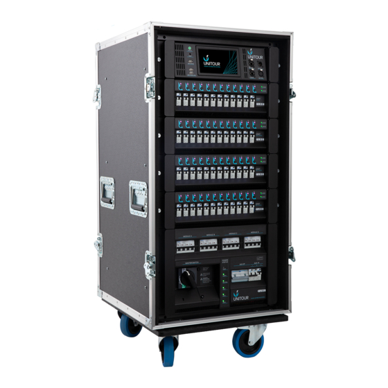
- Page 1 24 Channels 48 Channels UNITOUR ® with Optional Dimming User Manual LSC Control Systems © +61 3 9702 8000 info@lsccontrol.com.au Version 2.03 www.lsccontrol.com.au February 2023...
- Page 2 LSC Control Systems Pty Ltd. All Trademarks referred to in this manual are the registered names of their respective owners. The operating software of the UNITOUR and the contents of this manual are copyright of LSC Control Systems Pty Ltd © 2021.
-
Page 3: Table Of Contents
1.4.1 Options ......................8 1.4.2 Deluxe Models DMX Outputs ................9 Front Panel ......................10 1.6.1 Control Module (UHM, Unitour Head Module) ..........11 1.6.2 Setup without 3 Phase Power ................ 12 1.6.3 Output Modules Overview ................12 1.6.4 UDMT Dim + Switch Output Module .............. 13 1.6.5... - Page 4 UNITOUR Power System User Manual 4.6.2 Solo Inactive ....................26 Channel Modes ..................... 27 4.7.1 Always Off ..................... 27 4.7.2 Auto Power ....................27 4.7.3 Always On ..................... 28 4.7.4 Switch 60%-40% .................... 28 4.7.5 Relay 1%-0% ....................28 4.7.6 Dimmer ......................
- Page 5 UNITOUR Power System User Manual 4.21.5 Reset To Defaults ..................50 4.21.6 Delete Show Files ..................52 4.21.1 Set PIN Codes ....................52 4.21.2 Removing PIN codes ..................53 4.21.1 Update Software (Firmware) ................53 4.21.1 Configure Syslog ................... 54 Emergency Mode ..................
-
Page 6: Product Description
Illustrations in this manual show the “Deluxe” version of the UNITOUR. See section 1.4 1.2 UNITOUR Overview UNITOUR is a premium portable power solution for video, audio and lighting for the events, touring, film and TV markets. It is a totally flexible unit for power control of conventional, LED or moving lights and provides perfect power solutions for LED video walls and audio systems. - Page 7 LEDs and convention incandescent lamps. This mode is not available on USMT switch modules. The UNITOUR is all about safety for both the operator and the equipment attached to it. The power to each output is switched by internal relays. This allows UNITOUR to provide protection by switching off the power in the event of a lost neutral or if the input voltage is excessive or too low (configurable settings).
-
Page 8: Good Design Award
The Good Design Awards Jury commented: “A innovative way of providing power at live event, the UNITOUR individually monitors all device outputs to give operators complete peace of mind. The modular design is commendable, as is the dimmable 'stealth' front panel.”... -
Page 9: Deluxe Models Dmx Outputs
Art-Net and sACN and a DMX-RDM splitter. The 6 outputs are on the rear of the UNITOUR rack. There is a “DATA” LED immediately adjacent to each output showing if that channel output is active. It flickers when DMX is transmitted. -
Page 10: Front Panel
Indicators 24 Channel UNITOUR 48 Channel UNITOUR The top section contains the Control Module (also known as the UHM, Unitour Head Module). See section 1.6.1 below. The centre section contains the output modules. Each module has either 12 switched output channels or 12 switching/dimmer output channels. -
Page 11: Control Module (Uhm, Unitour Head Module)
The Control Module (also known as the UHM) is used to configure, control and monitor the UNITOUR rack and also to display the current system status and report any alarm conditions. It also acts as a control and reporting proxy to the outside world allowing all relevant information to be reported to LSC’s HOUSTON X monitoring and configuration software. -
Page 12: Setup Without 3 Phase Power
DMX THRU, 5 pin XLR female connector. It provides a loop output to feed other DMX equipment. Hint: LSC recommends the use of RS485 data cable or shielded CAT5 cable for the DMX connections. Audio or Microphone cables must not be used. -
Page 13: Udmt Dim + Switch Output Module
Time of 220µS (measured between 10% and 90% at 50% output level into maximum rated load). In switching mode, the module uses LSC’s “TruPower” technology that bypasses the dimmer circuitry and directly connects the output circuit to the incoming power via a mechanical relay. -
Page 14: Rear Panel
UNITOUR Power System User Manual 1.7 Rear Panel Deluxe model DMX outputs Work Light Earth Sense Lift See section Controlled 1.7.7 Outputs Earth Sense Lift Deluxe model See section DMX outputs 1.7.7 Work Light 1 Phase Auxiliary Control Outputs Module... -
Page 15: Power Status Indicators
“FAULT” LED lights is off. A full power cycle must then be performed (all power removed and restored) to remove the warning message on the screen. UNITOUR will operate with only 1 or 2 phases connected, provided that it has both a Neutral and an Earth connection. 1.7.4... -
Page 16: Home Screen
A red dot momentarily appears in the top right corner when settings are being saved to the internal memory • Show Name A show name appears here when the UNITOUR setup had been saved as a Show file or a Show file has been loaded. See section 4.18 • Control Source and Patch information... - Page 17 The Module Status pane on the right of the screen shows the type of output modules (Dimmer or Switch) that are fitted to the UNITOUR and in the top right corner of the pane is a green flashing heartbeat indicator that signifies that the Unity Head Module is operating correctly.
-
Page 18: Alarms And Indicators
UNITOUR Power System User Manual Alarms and Indicators If the system is operating correctly, the area to the left of the LOG IN button on the home screen will be blank and the large “STATUS” LED to the left of the screen is green. If an alarm is detected the “STATUS”... -
Page 19: Control Module Status Led
UNITOUR Power System User Manual To clear persistent alarms, tap the ALARMS button. Appears if a persistent alarm is active The CLR button appears on the Alarms Menu when there is a persistent alarm. Tapping CLR clears all persistent alarms. -
Page 20: Input Voltage And Current Limits
If any input currents above the limits they will activate an alarm. Currents above the limits are shown in yellow. The UNITOUR system is fully rated so it can supply full load current to all outputs. The alarm is provided for occasions when UNITOUR is connected to a limited current source. -
Page 21: Configuring Unitour
• Remotely using LSC’s HOUSTON X software. See section 6 UNITOUR can be configured without being connected to 3-phase power. Just connect a PoE Ethernet switch to the PoE Ethernet connector and the head module begins operating, allowing local (touch screen) or HOUSTON X (network) configuration. -
Page 22: Help
To close the help screen, tap anywhere within the help screen. 4.4 Quick Setup UNITOUR allows every output channel in the rack to have its own selectable control source, own Art-Net or sACN universe, its own DMX address, and its own operating mode. However, in most cases, the configuration is much simpler so UNITOUR provides a “Quick”... - Page 23 UNITOUR Power System User Manual UNITOUR can be fitted with two types of output modules, • UDMT = Dimmer/Switch module • USMT = Switch module The Control Module interrogates the rack and looks for the modules that are fitted. If the rack is connected to 3-phase power, the output modules will be automatically recognised as either UDMT (Dim/Switch) or USMT (Switch) modules.
- Page 24 UNITOUR Power System User Manual • DMX control. Tap DMX, NEXT. All “AUTO” channels are now controlled from the presence of a DMX signal (or the LOCAL CONTROL button). • Art-Net control. Tap Art-Net. The “ARTNET” screen appears. Enter the Net, Subnet and Universe numbers.
-
Page 25: Home Screen Menu Buttons
UNITOUR Power System User Manual • AUTO POWER. These channels will act as power switches and they will be sequentially switched on (to minimise in-rush currents) either manually from the LOCAL CONTROL button on the touch screen or, if their “Control Source” is set to DMX, Art-Net or sACN, they will be switched on by the presence of their control source. -
Page 26: Solo Is Active
UNITOUR Power System User Manual channels. Riggers Control cannot be used to control channels that have their mode set as “Always OFF” or “Always ON”. Riggers Control has two modes, “SOLO IS ACTIVE” or “SOLO INACTIVE”. Tap the SOLO button to toggle it between the two modes. -
Page 27: Channel Modes
UNITOUR Power System User Manual 4.7 Channel Modes From the “Home Screen” tap CHANNEL MODES. The screen shows the mode of each channel, Always Off, Auto Power, Always On, Switch, Relay or Dimmer. Channel 1 is selected Mode Buttons To change the “Mode” of a channel, tap the channel to select it. Multiple channels can be selected. -
Page 28: Always On
UNITOUR Power System User Manual the source DMX universe (DMX, Art-Net or sACN) according to the control source selected for that channel. The switch on sequence is started when they see a valid DMX signal from their selected source. When the selected control source is no longer detected, the Auto Power channels are switched OFF. - Page 29 UNITOUR Power System User Manual Channel 1 is selected Address AUTO channels do not have a Control DMX address Source Buttons Each channel can be individually configured to be controlled by any of the following control sources. • LOCAL (touch screen) •...
-
Page 30: Local
Channels set to “LOCAL” can be switched on or off from the touch screen. From the home screen tap LOCAL CONTROL. See section 4.11 4.8.2 Art-Net UNITOUR supports Art-Net v4. There are 128 Nets (0-127) each with 256 Universes divided into 16 Subnets (0-15), each containing 16 Universes (0-15). ▼... -
Page 31: Sacn
Art-Net packets. In UNITOUR’s network setup menu, the option to set the IP address is offered based on the ArtNet recommendations when using a 2.0.0.0. address range. See section 4.21.1 4.8.3... -
Page 32: Dmx Address
If multiple sACN sources with the same universe and priority level are received they will be merged on a HTP (Highest Takes Precedence) basis. Note: To use sACN, UNITOUR must have a valid IP address and NetMask set in order to work correctly. - Page 33 UNITOUR Power System User Manual Tap any channel button to see detailed information about that channel CONFIGURE View Currents Menu • Tap LOAD (Amps) to view the load current of every channel. • Tap LEAKAGE (mA) to view the earth leakage current of every channel.
-
Page 34: Configure Currents
UNITOUR Power System User Manual 4.9.1 Configure Currents In the “Channel Currents” menu (above) tap CONFIGURE. The “Configure Currents” screen allows you to reset the stored peak load and peak leakage currents and to set the warning thresholds for load current and earth leakage current for each output channel. -
Page 35: View Levels
RCD is close to tripping. To overcome this problem, when the UNITOUR rack is manufactured, every RCD is tested to determine its trip current and this value is stored and used to calculate the percentage of the leakage current that will trip the RCD. -
Page 36: Local Control
UNITOUR Power System User Manual 4.11 Local Control From the “Home Screen” tap LOCAL CONTROL. This menu allows you to control the brightness of the LED illumination and to switch the channels set to “Auto Power” mode on or off. -
Page 37: Advanced Menu
UNITOUR Power System User Manual • • NDI (future feature) • OSC (future feature) Tap a group to open its controls. For example, the “Local Group”. • To start the sequential switch on sequence (also known as a staggered start) tap START UP. -
Page 38: Stagger Time
UNITOUR Power System User Manual The start of the switch-on sequence (also known as a staggered start) of Auto Power channels can be either manually triggered from the touch screen by selecting the LOCAL CONTROL button (see section 4.11) or automatically triggered whenever the channels selected control signal is present. -
Page 39: Selecting Channels
UNITOUR Power System User Manual SELECT CHANNELS The 3 menu buttons are greyed out because no channels have yet been selected. 4.14.1 Selecting Channels To select the channel(s) via the touch screen, tap SELECT CHANNELS. Channel 1 is selected Blue line indicates a “Dim/Switch”... -
Page 40: Min Level
Note: The actual output voltage of the dimmer channel is dependent upon the dimmer curve. LSC recommends that you measure the output voltage (with a 240 volt load connected) to determine the “Max” level setting you require for a specific maximum voltage. This procedure should only be carried out by suitably qualified personnel. -
Page 41: Curves
It defines how the dimmers output voltage responds to the control signal input. UNITOUR provides several different curves and each has a different response. You can try each curve to see which one gives you the most linear results for you lighting fixtures. If your rig also has some other types of dimmers you can experiment to find which curve gives the best match to those dimmers. -
Page 42: View Channels
UNITOUR Power System User Manual Multiple channels are selected and they are using different Curves 4.15 View Channels The “View Channels” menu can be used to view all of the settings for the channel that you select. From the “Home Screen” tap LOG IN, ADVANCED, VIEW CHANNELS then select a channel to view. - Page 43 Make your selection then tap SAVE. • Tap sACN to open a new screen where you select the sACN Universe to view. Make your selection then tap SAVE • Tap CHANNEL INPUT to display the values at the input of each UNITOUR channel. Page 43...
-
Page 44: View Logs
ARCHIVES, tap on the desired archive file then tap LOAD. 4.18 Load/Save The user settings of a UNITOUR rack can be saved and recalled from the internal memory or they can be exported or imported from a USB memory stick. The file is known as a “show” and each show can be individually named using the pop-up on-screen keyboard. -
Page 45: Dmx Outputs / Demux Setup
The 6 output ports are labelled A through F. Each port can be individually configured to output DMX from any of the control signals that are being received by UNITOUR (Art-Net, sACN, DMX) or can be set to OFF. All DMX512-A/RDM outputs are galvanically isolated to 1500 volts and short circuit protected. -
Page 46: Set Power Limits
Voltages outside the limits are shown in red. UNITOUR monitors the input currents of all 3 input phases and the neutral. You can set a current warning alarm for each input phase and the neutral. An alarm is activated if a warning level is reached. -
Page 47: System Setting
DEFAULT DHCP This menu is used to select the IP address that is used for this UNITOUR rack. The network address can be set manually (known as a Static IP) or it can be automatically assigned by your network using a DHCP server. The setting of IP addresses is dependent on the network being used and the choice of static or DHCP and other network parameters is beyond the scope of this document. -
Page 48: Configure Alarms
The “Configure Alarms” menu lists all of the “conditions” that UNITOUR continuously monitors and allows you to select which conditions will trigger an ALARM or generate an entry into the UNITOUR LOG or send a message to HOUSTON X or SYSLOG, when a change in condition is detected. -
Page 49: Set Date And Time
4.21.3 Set Date and Time UNITOUR has an internal clock that is used for various purposes such as logging the date and time of events and peaks. The clock can be manually set or it can be automatically set by a network connection. -
Page 50: Set Rack Name
4.21.4 Set Rack Name Every UNITOUR rack can be given a name. Names might indicate the physical location of the channels, for example, one rack might be named “Front of House” and another “Stage”. Tap LOG IN, ADVANCED, SYSTEM SETTINGS, SET RACK NAME. Tap inside the name box then use the pop-up keyboard to enter a name. - Page 51 UNITOUR Power System User Manual Demux Outputs A through F Rack Name No Name Local Settings Defaults Parameter Default Setting Minimum Volts Maximum Volts 265V Current Warning 24 Channels = 150A 48 Channels = 300A Neutral Max Volts Neutral Current Warning...
-
Page 52: Delete Show Files
OK 4.21.1 Set PIN Codes Access to UNITOUR can be restricted by PIN codes. Four access levels are provided. • USER. This level locks the 6 menu buttons at the bottom of the “Home Screen” and the “QUICK”... -
Page 53: Removing Pin Codes
LSC Control Systems has a corporate policy of continuous improvement to its products. The UNITOUR software (firmware) is subject to this policy as new features are added and existing features improved. The software version of your UNITOUR can be checked by tapping ? in the top left corner of the “Home Screen”. -
Page 54: Configure Syslog
This allows a single computer to monitor any number of UNITOUR racks on a network and store their log messages and act on them if desired. -
Page 55: Emergency Mode
HOUSTON X can also control every compatible connected LSC product (GEN VI, APS, MDRD, LED-CV4, UNITOUR, UNITOUR). You can use it to set a DMX address, set a channel to dimmer or Switch (TruPower), check the temperature, test a channel (rigger’s control), find DMX cabling faults etc. -
Page 56: Output Connectors
UNITOUR Power System User Manual Output Connectors The UNITOUR can be supplied with the following types of power output connectors: • Dual (parallel wired) Wieland 16-pole multipin sockets • Dual (parallel wired) Wieland 10-Pole multipin sockets • Dual (parallel wired) Socapex 19-pin multipin sockets 7.1 Dual (parallel wired) Wieland 16-pole Multipin Sockets... -
Page 57: Dual (Parallel Wired) Socapex 19-Pin Multipin Sockets
In 3 phase power systems it is desirable that the output loads are distributed as evenly as is practical between the 3 input phases, Live 1, Live 2 and Live 3. The outputs of each UNITOUR output module are fed from the following input phases: Output Channel Input Phase... -
Page 58: Specifications
+ neutral within the rack Internal configuration and control of all USMT (switch) and UDMT (switch/dim) modules Remote monitoring and configuration via LSC’s HOUSTON X software suite Optional ability to send SMS messages to relevant personnel if a problem arises (Future feature) Neutral loss and over-voltage protection. - Page 59 UNITOUR Power System User Manual Optional programmable RCD module for 400A circuit breaker, controlled from UHM control module PowerLock 400A, 5-wire (TN-S) 230/415V supply in and thru CEE 32A 3-phase auxiliary power output socket; Australian models fitted with 32A 3-phase output socket protected by 32A 4-pole RCBO (Type A) Three CEE 16A single-phase auxiliary power output sockets;...
- Page 60 Circuit breakers and labelling stripe with dimmable stealth LED illumination Peace of Mind CE (European) and RCM (Australian) approved Two-year warranty Designed and manufactured in Australia by LSC, an Australian owned company with over 40 years’ experience in developing world-first dimmer products Page 60...
-
Page 61: Feature History
UNITOUR Power System User Manual 10 Feature History The new features added to UNITOUR in each software release are listed below: Release: V2.03 Delete show files. A new button allows you to delete old show files. Factory Reset. A new button allows you to rest the unit to factory defaults. There are several options as to which parts to reset. -
Page 62: Terminology
ArtNet (designed by and copyright, Artistic Licence Holdings Ltd) is a streaming protocol to transport multiple DMX universes over a single Ethernet cable/network. UNITOUR supports Art-Net v4. There are 128 Nets (0-127) each with 256 Universes divided into 16 Subnets (0-15), each containing 16 Universes (0-15). -
Page 63: Compliance Statements
UNITOUR Power System User Manual 12 Compliance Statements The UNITOUR from LSC Control Systems Pty Ltd meets all required CE (European), RCM (Australian) and UKCA (United Kingdom) standards. CENELEC (European Committee for Electrotechnical Standardization). Australian RCM (Regulatory Compliance Mark). UK Conformity Assessed.
Need help?
Do you have a question about the UNITOUR and is the answer not in the manual?
Questions and answers