
Subscribe to Our Youtube Channel
Related Manuals for LSC UNITOUR


Summary of Contents for LSC UNITOUR
- Page 1 24 Channels 48 Channels UNITOUR with Optional Dimming User Manual LSC Control Systems © +61 3 9702 8000 info@lsccontrol.com.au Version 2.0 www.lsccontrol.com.au December 2021...
- Page 2 LSC Control Systems Pty Ltd. All Trademarks referred to in this manual are the registered names of their respective owners. The operating software of the UNITOUR and the contents of this manual are copyright of LSC Control Systems Pty Ltd © 2021.
-
Page 3: Table Of Contents
1.3.1 Deluxe Models ....................8 1.3.2 Options ......................8 Front Panel ......................10 1.5.1 UHM (UNITOUR Head Module) ..............11 1.5.2 Setup without 3 Phase Power ................ 12 1.5.3 Output Modules Overview ................12 1.5.4 UDMT Dim + Switch Output Module .............. 13 1.5.5... - Page 4 UNITOUR Power System User Manual 3.6.6 DIMMER ......................26 SOURCE/PATCH ....................26 3.7.1 Control Source ....................27 3.7.2 Patch ......................28 VIEW CURRENTS ....................28 3.8.1 Configure Currents..................30 View Levels......................31 3.10 Control ........................32 3.10.1 LED Illumination ..................... 32 3.10.2...
- Page 5 UNITOUR Power System User Manual Specifications ..................51 Compliance Statements ............... 54 Page 5...
-
Page 6: Product Description
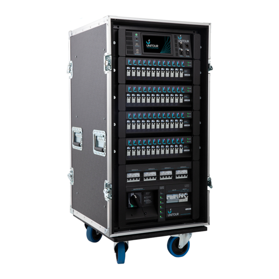
Illustrations in this manual show the “Deluxe” version of the UNITOUR. See section 1.3 1.2 UNITOUR Overview UNITOUR is a premium portable power solution for video, audio and lighting for the events, touring, film and TV markets. It is a totally flexible unit for power control of conventional, LED or moving lights and provides perfect power solutions for LED video walls and audio systems. - Page 7 This mode is not available on USMT switch modules. The UNITOUR is all about safety for both the operator and the equipment attached to it. This protection includes dropped neutral protection (the rack will shut down in the event of a...
-
Page 8: Sizes And Options
Deluxe models are fitted with an internal 6 port DMX512-A/RDM / Ethernet converter and DMX-RDM splitter supporting Art-Net and sACN. The 6 DMX512-A/RDM outputs are on the rear of the UNITOUR rack. Delux Model DMX512-A Outputs All DMX512-A/RDM outputs are galvanically isolated to 1500 volts and short circuit protected. - Page 9 UNITOUR Power System User Manual Choice of output connectors, • Socapex 19-pin • Wieland 16-pole • Wieland 10-pole Optional top mounted patch bay providing 2:1 parallel patching of every output plus two connectors and ammeter for load/lamp testing. See section 8 for all specifications.
-
Page 10: Front Panel
24 Channel UNITOUR 48 Channel UNITOUR The top section contains the UHM (UNITOUR Head Module). See section 1.5.11.7.4 The centre section contains the output modules. Each module has either 12 switched output channels or 12 switching/dimmer output channels. Each output channel has its own RCBO circuit breaker. -
Page 11: Uhm (Unitour Head Module)
1.5.1 UHM (UNITOUR Head Module) The UHM is used to configure, control and monitor the UNITOUR rack and also to display the current system status and report any alarm conditions. It also acts as a control and reporting proxy to the outside world allowing all relevant information to be reported to LSC’s HOUSTON X monitoring and configuration software. -
Page 12: Setup Without 3 Phase Power
3 phase power. It only requires a PoE Ethernet switch to connect to the UHM control module which will power the UHM allowing the UNITOUR to be configured using the touch screen or via LSC’s HOUSTON X via a laptop or tablet. -
Page 13: Udmt Dim + Switch Output Module
Time of 220µS (measured between 10% and 90% at 50% output level into maximum rated load). In switching mode, the module uses LSC’s “TruPower” technology that bypasses the dimmer circuitry and directly connects the output circuit to the incoming power via a mechanical relay. -
Page 14: Rear Panel
UNITOUR Power System User Manual 1.7 Rear Panel Deluxe model DMX outputs Work Light Controlled Work Deluxe model Outputs Light DMX outputs 1 Phase Auxiliary Outputs Fuses Power 3 Phase Controlled Status Auxiliary Outputs Indicators Output Fuses PowerLock Inputs Earth... -
Page 15: Power Status Indicators
“FAULT” LED lights is off. A full power cycle must then be performed (all power removed and restored) to remove the warning message on the screen. UNITOUR will operate with only 1 or 2 phases connected provided that it has both a Neutral and an Earth connection. -
Page 16: Home Menu
A red dot momentarily appears in the top right corner when settings are being saved to the internal memory • Show Name A show name appears here when the UNITOUR setup had been saved as a Show file or a Show file has been loaded. See section 3.20 • Input Voltages and Currents The central section of the screen shows a real time display of the RMS voltage and currents across all 3 input phases and the neutral. -
Page 17: Alarms And Warnings
The Module Status pane on the right of the screen shows the type of output modules (Dimmer or Switch) that are fitted to the UNITOUR and in the top right corner of the pane is a green flashing heartbeat indicator that signifies that the Unity Head Module is operating correctly. -
Page 18: Uhm Status Led
You can set which conditions will activate an alarm. See section 3.21.2. UNITOUR can also send SMS messages to relevant personnel if an alarm is detected. This is a future feature. 2.1.1 UHM STATUS LED •... -
Page 19: Voltage And Current Warnings
Voltages outside the limits are shown in red. UNITOUR monitors the input currents of all 3 input phases and the neutral. You can set a current warning alarm for each input phase and the neutral. An alarm is activated if a warning level is reached. -
Page 20: Configuring Unitour
3.2 Menu Access Levels LOG IN Home Menu There are 3 “Levels” of access to UNITOUR. Each level can be PIN protected to restrict un authorised access. See section 3.22.1 • USER. This level consists of the 6 menu buttons at the bottom of the “Home Menu”... -
Page 21: Quick Setup
When starting a new configuration it is recommended that you clear any previous configuration and reset the UNITOUR back to the factory default settings. This will set all channels to “Auto Power” mode and “LOCAL” control. If you tap NO and do not do a reset, the output channels will remain in their last used configuration. - Page 22 UNITOUR Power System User Manual Tap the type of module (Switch or Dimmer) that is or will be fitted in each module location, A through D from top to bottom of the rack. Tap NEXT to set the external control source for all channels.
- Page 23 UNITOUR Power System User Manual Blue line indicates a Dim/Switch Module Green line indicates a Switch only Mode Module Buttons The “Channel Mode Select” menu has a button for each channel that shows its current mode. By default, all channels are set to Auto Power mode. To accept this setting tap DONE however if you want any channels to operate in different modes, follow the directions below.
-
Page 24: Home Screen Menu Buttons
UNITOUR Power System User Manual with long fade times. The “Relay” channel will switch on at the start of the up fade and switch off at the end of the down fade. • DIMMER (not available on USMT switch modules). The channel will act as a dimmer and it level is individually controlled by the DMX level of a slot to which it is patched. -
Page 25: Solo Inactive
UNITOUR Power System User Manual • A channel that is on can be turned off by tapping that channel again. “Solo” mode provides a fast method of identifying channels because the channel that you tap will be the only channel that is on. -
Page 26: Always Off
UNITOUR Power System User Manual Each channel can be individually configured to operate in one of the following modes, 3.6.1 ALWAYS OFF The channel cannot be turned on, except in “Emergency Mode”. See section 4. Warning, do not rely on this setting to isolate the power. -
Page 27: Control Source
UNITOUR Power System User Manual 1. Tap the required channels to select them 2. Tap a “Control Source” for the selected channels. If you select Art-Net or sACN you must also select the required Universe settings 3. Tap PATCH and enter the DMX address These steps are described in detail below. -
Page 28: Patch
DMX addresses, the “Home” menu displays the word “Patched”. Hint: To use sACN or Art-Net protocols, UNITOUR must have a valid IP address and NetMask set in order to work correctly. When using Art-Net, it is essential that the IP address is set to be compatible with the address on the device sending the Art-Net packets. - Page 29 UNITOUR Power System User Manual Tap any channel button to see detailed information about that channel View Currents Menu • Tap LOAD (Amps) to view the load current of every channel. • Tap LEAKAGE (mA) to view the earth leakage current of every channel.
-
Page 30: Configure Currents
UNITOUR Power System User Manual 3.8.1 Configure Currents In the “Channel Currents” menu (above) tap CONFIGURE. The “Configure Currents” screen allows you to reset the stored peak load and peak leakage currents and also to set the warning thresholds for load current and earth leakage current for each output channel. -
Page 31: View Levels
20mA and 30mA of leakage. This can make it difficult to know when a RCD is close to tripping so when the UNITOUR rack is manufactured, every RCD is tested to determine its trip current and this value is stored and used to calculate the percentage of the leakage current that will trip the RCD. -
Page 32: Control
UNITOUR Power System User Manual 3.10 Control From the “Home Menu” tap CONTROL. 3.10.1 LED Illumination The “LED Illumination” pane has sliders that allow you to adjust the brightness of the LCD touch screen and the brightness of the rack illumination LEDs 3.10.2... -
Page 33: Advanced, Main Menu
UNITOUR Power System User Manual 3.11 Advanced, Main Menu From the “Home Menu” tap LOG IN then touch ADVANCED. The “Main Menu” screen opens. Main Menu Note: In all of the following menus, the SAVE button only appears if you have altered a setting. -
Page 34: Dimmer Setup
UNITOUR Power System User Manual The “Stagger Time” can be set to any value from 0.1 to 2.5 seconds. This is the time interval between each “Auto Power” channel turning on. The “Hold Time” can be set to any value from 0 to 30 minutes. When the control source is no longer detected the hold time starts counting down. -
Page 35: Min Level
Note: The actual output voltage of the dimmer channel is dependent upon the dimmer curve. LSC recommends that you measure the output voltage (with a 240 volt load connected) to determine the “Max” level setting you require for a specific maximum voltage. This procedure should only be carried out by suitably qualified personnel. -
Page 36: Curves
It defines how the dimmers output voltage responds to the control signal input. UNITOUR provides several different curves and each has a different response. You can try each curve to see which one gives you the most linear results for you lighting fixtures. If your rig also has some other types of dimmers you can experiment to find which curve gives the best match to those dimmers. -
Page 37: View Channels
UNITOUR Power System User Manual • Quad Law • INV Square. Future feature. • LED 1. Future feature. • LED 2. Future feature. Tap a curve name to select it then tap SAVE. If multiple channels are selected and they have currently have different curves selected, then all the curves in use are highlighted in yellow as shown below. -
Page 38: View Sources
CHANNEL INPUT Selected 3.16 View Logs UNITOUR automatically recognises condition changes that occur in the system and stores them in a log. You can select the types of condition changes that will generate an entry into the log. See section 3.21.2. -
Page 39: Configure Art-Net
Art-Net packets. In UNITOUR’s network setup menu, when using Art-Net, the option to set the IP address is offered based on the ArtNet recommendations when using a 2.0.0.0. address range. See section 3.21.1... -
Page 40: Configure Sacn
Configure sACN Tap the up or down buttons to select the universe to which the UNITOUR rack will respond then tap SAVE. If sACN is enabled, any matching universes on the network will appear in the bottom right window. -
Page 41: Load/Save
Neutral current = 250A 3.20 Load/Save The user settings of a UNITOUR rack can be saved and recalled from the internal memory or they can be exported or imported from a USB memory stick. The file is known as a “show” and each show can be individually named using the pop-up on-screen keyboard. -
Page 42: System Setting
Tap LOG IN, ADVANCED, SYSTEM SETTINGS, NETWORK. This menu is used to select the IP address that is used for this UNITOUR rack. The network address can be set manually known as a Static IP or it can be automatically assigned by your network using a DHCP server. -
Page 43: Configure Alarms
Tap SAVE to keep your settings and exit. Note. To use sACN or Art-Net protocols, UNITOUR must have a valid IP address and NetMask set in order to work correctly. When using Art-Net, it is essential that the IP address is set to be compatible with the address on the device sending the Art-Net packets. -
Page 44: Set Date And Time
Alternatively, to automatically set the date and time by a network connection tap ENABLE NTP. NTP (Network Time Protocol) is a networking protocol for clock synchronization over networks. You can connect UNITOUR to an NTP server or you can create your own NTP time server and run it on a private network. -
Page 45: Set Rack Name
3.21.4 Set Rack Name Every UNITOUR rack can be given a name. Names might indicate the physical location of the channels, for example, one rack might be named “Front of House” and another “Stage”. Tap LOG IN, ADVANCED, SYSTEM SETTINGS, SET RACK NAME. Tap inside the name box then use the pop-up keyboard to enter a name. -
Page 46: Reset To Defaults
Home menu, see section 3.4. • ADVANCED, see section 3.11. • SERVICE. This level is always locked and requires a PIN. Contact LSC for access. • HOUSTON. This allows remote configuration and monitoring using LSC’s HOUSTON X software. See section 5 UNITOUR ships with the “USER”, “ADVANCED”... -
Page 47: Update Firmware
Menu by tapping ? in the top left corner of the “Home Menu”. The latest firmware for UNITOUR can be downloaded from the LSC website. On a USB memory stick, create a folder called LSC (in the root directory) and copy the upgrade file into the LSC folder. -
Page 48: Emergency Mode
ON state. WARNING. Use this method of turning on a channel only as a last resort. LSC Control Systems takes no responsibility for any damage this might cause to connected equipment because the protection systems of the UNITOUR are disabled in this mode. -
Page 49: Houston X
HOUSTON X can also control every compatible connected LSC product (GEN VI, APS, MDRD, LED-CV4, UNITOUR, UNITOUR). Set a DMX address, set a channel to dimmer or Switch (TruPower), check the temperature, test a channel (rigger’s control), find DMX cabling faults etc. -
Page 50: Output Connectors
UNITOUR Power System User Manual Output Connectors The UNITOUR can be supplied with the following types of power output connectors: • Dual (parallel wired) Wieland 16-pole multipin sockets • Dual (parallel wired) Wieland 10-Pole multipin sockets (future release) • Dual (parallel wired) Socapex 19-pin multipin sockets 6.1 Dual (parallel wired) Wieland 16-pole Multipin Sockets... -
Page 51: Phasing
In 3 phase power systems it is desirable that the output loads are distributed as evenly as is practical between the 3 input phases. The outputs of each UNITOUR output module are fed from the following input phases: Output Channel Input Phase... - Page 52 UNITOUR Power System User Manual Optional ability to send SMS messages to relevant personnel if a problem arises (Future feature) Neutral loss and over-voltage protection. The rack will shut down in the event of a dropped neutral until the fault is...
- Page 53 Circuit breakers and labelling stripe with dimmable stealth LED illumination Peace of Mind CE (European) and RCM (Australian) approved Two-year warranty Designed and manufactured in Australia by LSC, an Australian owned company with over 40 years’ experience in developing world-first dimmer products Page 53...
- Page 54 UNITOUR Power System User Manual Compliance Statements The UNITOUR from LSC Control Systems Pty Ltd meets all required CE (European) and RCM (Australian) standards. European Committee for Electrotechnical Standardization (CENELEC). Australian RCM (Regulatory Compliance Mark). -END- Page 54...
Need help?
Do you have a question about the UNITOUR and is the answer not in the manual?
Questions and answers