Table of Contents
Advertisement
Quick Links
SPECIFICATIONS.............................................................................................................................................. 1
EXTERNAL DIMENSIONS................................................................................................................................. 2
WIRING DIAGRAMS.......................................................................................................................................... 3
ELECTRICAL PARTS........................................................................................................................................ 4
MICROCOMPUTER CONTROL SYSTEM......................................................................................................... 5
PRINTING WIRING DIAGRAM.......................................................................................................................... 6
FUNCTIONS....................................................................................................................................................... 7
TROUBLESHOOTING GUIDE OF CONTROL CIRCUIT................................................................................... 11
REFRIGERATION CYCLE................................................................................................................................. 14
PERFORMANCE CURVES............................................................................................................................... 15
DISASSEMBLING PROCEDURE...................................................................................................................... 16
REPARTMENT PARTS LIST............................................................................................................................. 26
SERVICE MANUAL
SPLIT SYSTEM
ROOM AIR CONDITIONER
MODEL
MODEL
CONTENTS
INDOOR UNIT
AH-PG21
OUTDOOR UNIT
AU-PG21
Advertisement
Table of Contents

Related Manuals for Sharp AH-PG21


Summary of Contents for Sharp AH-PG21
-
Page 1: Table Of Contents
SERVICE MANUAL SPLIT SYSTEM ROOM AIR CONDITIONER INDOOR UNIT AH-PG21 MODEL OUTDOOR UNIT AU-PG21 MODEL CONTENTS SPECIFICATIONS.............................. 1 EXTERNAL DIMENSIONS..........................2 WIRING DIAGRAMS............................3 ELECTRICAL PARTS............................4 MICROCOMPUTER CONTROL SYSTEM......................5 PRINTING WIRING DIAGRAM.......................... 6 FUNCTIONS............................... 7 TROUBLESHOOTING GUIDE OF CONTROL CIRCUIT................... 11 REFRIGERATION CYCLE.......................... -
Page 2: Specifications
CHAPTER 1. PRODUCT SPECIFICATION [1] SPECIFICATION 1. AH-PG21 / AU-PG21 INDOOR UNIT OUTDOOR UNIT ITEMS AH-PG21 AU-PG21 Cooling capacity 5.30 Moisture removal Liters/h – Electrical data Phase Single Rated frequency Rated voltage Rated current Rated input * 1720 Power factor... -
Page 3: External Dimensions
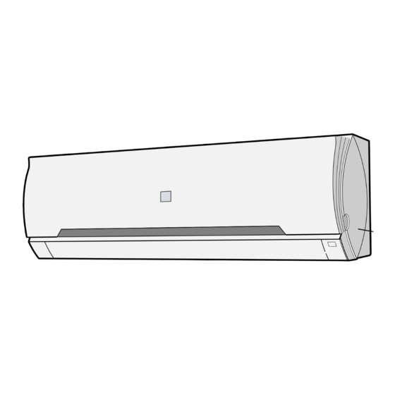
[2] EXTERNAL DIMENSION 1. Indoor unit (AH-PG21) 2. Outdoor unit (AU-PG21) -
Page 4: Wiring Diagrams
[3] WIRING DIAGRAM Indoor Unit (AH-PG21) Outdoor Unit (AU-PG21) -
Page 5: Electrical Parts
CHAPTER 2. ELECTRIC CIRCUIT [1] ELECTRIC PARTS 1. INDOOR UNIT (AH-PG21) PART NO. PART NAME ITEM SPECIFICATION Terminal Board Rating 300V,25A Fan motor Capacitor Rating 450V, 2 µ Relay-1 Rating AC250V,20A (RY1) Coil Volt: 12V Printed Wiring Board Material Paper Base Phenolic Resin (UL 94V-0) -
Page 6: Microcomputer Control System
[2] MICRO-COMPUTER CONTROL SYSTEM 1. Electronic Control Diagram Indoor unit (AH-PG21) -
Page 7: Printing Wiring Diagram
2. PRINTED WIRING DIAGRAM 1 Indoor (AH-PG21) -
Page 8: Functions
Fan speeds are given by the indoor fan motor, "DL"~"HH" which are available in the following operation mode. 2. OPERATION MODES 2.1. COOL operation AH-PG21 Fan switch Fan switch The compressor turns on or off, at the thermostat lines C3 and (r.p.m) - Page 9 4. TEST OUTPUTS IN EACH OPERATION MODE If the "AUX" button on the unit is pressed for 5 seconds or more during operation, cool test operation starts. The operation LED (red) Outdoor Indoor Mode Valve Coil Compressor Fan Motor Fan Motor flickers during test run.
- Page 10 AH-PG21 11. Test mode Keep pushing the "AUX." buttons and supply the power, the system will go to the test mode. In this mode, the output of operation is switched by pushing the "AUX." button in the unit or the "OI" button in the remote controller.
- Page 11 [3] DIAGNOSIS PROCEDURE When indoor fan motor is out of order or compressor lock occurs, indoor fan motor, outdoor fan motor, and louver are all stopped and the operation LED(red) turns on or off synchronously with the timimg of the timer LED. When the thermistor for room temperature or pipe temperature is open or short state, the operation LED turns on or off synchrnoously with the timing of the timer LED by pushing continously for more than 5 seconds "AUX."...
-
Page 12: Troubleshooting Guide Of Control Circuit
CHAPTER 4. TROUBLESHOOTING... - Page 14 CHAPTER 5. TROUBLESHOOTING...
-
Page 15: Refrigeration Cycle
CHAPTER 6. REFRIGERANTION CYCLE AND PERFORMANCE CURVES [1] REFRIGERANT CYCLE Capillary tube... -
Page 16: Performance Curves
[2] PERFORMANCE CURVES 1 – 14... -
Page 17: Disassembling Procedure
MODEL: AH-PG21 [1] INDOOR UNIT 1. Disassembling procedure of the indoor unit 1) Open the open panel, remove 2 Air Filters. 4) Remove the screw fixing the Cord holder. 2) Open the Louver frame, unlooks the hooks, pull the unit. - Page 18 7) Remove a screw fixing the Control box cover. 10) Remove the Thermistor of the Evaporator. 11) Remove Connector. 8) Cut the fixing band and remove the Cover B. 12) Cut the fixing band and remove the Holder. 9) Remove a screw fixing the ground wire.
- Page 19 13) Remove 2 screws fixing the Control box and remove it. 16) Remove 3 screws fixing the Evaporator. 17) Remove the Evaporator from the Cabinet. 14) Remove a screw fixing the drain pan and pull Drain pan toward you. 18) Remove 4 screws fixing the Side cover R, and pull the - Cross flow fan 19) Loose a screw fixing Cross flow fan.
- Page 20 2. The Electric Control box. 1) Remove the screw fixing the Receiving filter. 4) Remove a screw fixing the Cord holder and 2 screw fixing the Terminal board. 2) Remove the 2 Switch and Photo detector unit. 5) Remove 2 screws fixing the Transformer and pull the Control board unit.
- Page 21 2. Disassembling procedure of the fan 1) Loose the fan nut and fan can take out. 2) Loose 2 screw fixing the fan motor angle. 3) Cut the nylon band and loose 4 screws fixing the fan motor...
- Page 22 4-10 4-11 AH-PG21 [1] INDOOR UNIT PARTS 1-28 1-36 1-30 1-31 1-26 1-31 1-18 1-37 1-38 2-13 2-12 1-46 2-17 2-16 1-41 1-29 1-47 2-10 1-48 2-14 2-11 1-32 1-35 2-18 1-10 1-17 1-10 1-16 2-15 1-22 1-14 1-10 1-13...
- Page 24 SERVICE MANUAL REPLACEMENT PARTS LIST ( AH-PG21 ) REF.No. PART No. DESCRIPTION Q'TY CABINET AND UNIT PARTS 1 - 1 CMOT-A405JBKZ FAN MOTOR SUB ASS'Y 1 - 2 PGUMMA390JBE0 FAN MOTOR 1 - 3 CMOTLA999JBEZ FAN MOTOR 1 - 4...
- Page 25 1 - 35 LHLD-A830JBFA HOLDER 1 - 36 LHLD-A277JBF0 TUBE HOLDER 1 - 41 QW-VZF487JBZZ LEAD WIRE 1 - 43 TSPC-F703JBRZ NAME LABEL 1 - 44 TLABCC211JBRZ WIRING DIAGRAM 1 - 45 HBDG-A142JBEA BADGE 1 - 46 PFPFPC793JBEZ INSULATOR 1 - 47 PFPFPD061JBEZ FLOCKY TAPE 1 - 48...
- Page 26 4 - 1 CRMC-A707JBEZ REMOTE CONTROL 4 - 2 UBATUA027JBE0 BATTERY PACK 4 - 3 LHLD-A535JBFB CORD HOLDER 4 - 4 XTTS740P20000 TAPPING SCREW 4 - 5 LX-NZA207JBEZ SPECIAL NUT 4 - 7 PPLTNA061JBWZ MOUNTING ANGLE 4 - 8 XTTS740P30000 TAPPING SCREW 4 - 9 TINSEA505JBRZ...
-
Page 27: Repartment Parts List
COMPRESSOR COVER 1 - 13 PSEL-C017JBEZ CABINET SEAL 1 - 14 TSPC-F704JBRZ NAME LABEL 1 - 15 TLABBA100JBRA SHARP BADGE 1 - 16 CCHS-A777JBTB BASE PAN ASS'Y 1 - 17 FANG-A005JBKZ ANGLE ASS'Y 1 - 18 PSEL-C264JBEZ BULKHEAD INSULATOR B... - Page 28 CONTROL BOX PARTS 2 - 2 LHLD-A544JBFA CORD CLAMP HOLDER 2 - 3 QW-IZA031JBZZ COMPRESSOR CORD 2 - 4 RC-HZA531JBZZ RUNNING CAPACITOR 2 - 5 RC-HZA404JBZZ FAN MOTOR CAPACITOR 2 - 6 QTANZA002JBZZ TERMINAL BOARD 2 - 7 LHLD-A539JBFA CORD HOLDER 2 - 8 PBOX-A379JBWZ CONTROL BOX...
Need help?
Do you have a question about the AH-PG21 and is the answer not in the manual?
Questions and answers