Table of Contents
Advertisement
Quick Links
Advertisement
Table of Contents

Related Manuals for TeeJet RX410p


Summary of Contents for TeeJet RX410p
- Page 2 RX410p Copyrights © 2007 TeeJet Technologies Inc. All rights reserved. No part of this document or the computer programs described in it may be reproduced, copied, photocopied, translated, or reduced in any form or by any means, electronic or machine readable, recording or otherwise, without prior written consent from TeeJet Technologies, Inc.
-
Page 3: Table Of Contents
APPENDIX A - TROUBLESHOOTING ......21 APPENDIX B - RX410P SPECIFICATIONS ..... 23... -
Page 5: Chapter 1 - Introduction
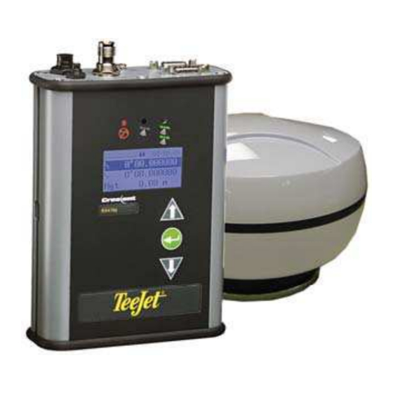
CHAPTER 1 - INTRODUCTION The RX410p is a GPS receiver and antenna system that tracks GPS and SBAS. The high accuracy, multipurpose receiver is capable of receiving GPS and SBAS signals as well as optional radio bea- con. This system is upgradeable to output messages up to 20Hz. The menu system provides easy system configuration and the status LEDs provide quick updates on the receiver condition. -
Page 6: Installation
Open the shipping box and examine the contents for signs of damage. Please notify the shipper and TeeJet Customer Support of any damage to the shipping box or its contents immediately. Make sure all items have been received. Contents may vary depending upon the system ordered. The following table lists standard components that should arrive with an RX410p system. -
Page 7: Receiver
98-05099 Receiver It is not necessary to mount the RX410p receiver. However, if mounting is desired, several thumb screws, nuts, and brackets are provided in the kit. When choosing a mounting location, please ensure the menu screen, LEDs, and buttons are visible and accessible. Access to the back panel must be available for switching out cables and accessing the POWER button. -
Page 8: Antenna
To install the brackets for mounting: Slide the nuts through the openings along the sides of the receiver. Place the bracket along the receiver and insert the thumbscrews so they screw into the nuts. Secure the brackets in the location of choice. Antenna Placement of the antenna is crucial to the system’s operation. -
Page 9: Cable Interface
Connect the data port(s) to any required device. EXTERNAL DEVICE CONNECTIONS The serial ports of the RX410p operate at the RS-232C interface level to communicate with external data loggers, navigation systems, and other devices. The two serial ports are accessible via the back panel. - Page 10 Figure 1-3: DB9 Socket Numbering Note: For successful communication, the baud rate of the RX410p serial ports must be set to match that of the devices to which they are connected. Tables 1-2 and 1-3 provide the pin configuration for the serial ports.
- Page 11 SBAS (WAAS, EGNOS, MSAS, etc.) ® e-Dif External RTCM ® L-Dif Table 1-5: Serial Port Settings Serial Port Baud Rate Data Bits Parity Stop Bits Interface Level Serial Port A 4800 None R2-232C and B 9600 19200 38400 57600 RX410P 98-05099 R0...
-
Page 12: Serial Ports
The antenna is designed to be used outdoors. NOTE: The changes made to the RX410p via the serial port will not be saved to memory for subse- quent power-up unless a save command is issued ($JSAVE). If changes are made via the menu system, they are saved automatically. -
Page 13: Chapter 2 - Operation
NOTE: The RX410p can take up to 5 minutes for a full ionospheric map to be received from SBAS. Optimum accuracy will be obtained once the RX410p is processing corrected positions using complete ionospheric information. -
Page 14: Main Menu
MAIN MENU The menu system of the RX410p is designed for easy setup and configuration in the field or in the office. Most configuration can be completed entirely through the menu system without having to con- nect to a computer or PDA. The menu software supports many different languages so individuals with varied backgrounds can easily understand the configuration of the receiver. - Page 15 ARM: Solution Figure 2-5: Main Menu E CH-SV EI (Satellite Elevations) Satellites AZ SNR (Satellite Azimuth and Signal to Noise GPS (con- Elevation Mask tinued) Maximum DGPS Age Data Port A Configure Data Port B UTC Offset RX410P 98-05099 R0...
- Page 16 Figure 2-6: Main Menu F Enter Name Differential Age Data PORT A Data PORT B Config Wizard Proceed Wizard Create New Elevation Mask Maximum DGPS Age Port A Port B Figure 2-7: Main Menu G Save to Location Save to Create New Not Used 1 Location...
- Page 17 Not Used 4 Not Used 5 Cancel Figure 2-9: Main Menu I In Use Other SwapApplications Display Apps System Display Update Setup Latitude and Longitude Units Use Previous Height Unit Velocity Unit PORT A Baud Rates PORT B RX410P 98-05099 R0...
- Page 18 Figure 2-10: Main Menu J System Display Logs Setup (Continued) Bin1 Bin2 Bin80 Bin93 Figure 2-11: Main Menu K Bin94 Bin95 Display Logs Bin96 (Continued) Bin97 Bin98 System Setup Bin99 (Continued) RCTM PCSI,1 Menu System Software Disp Crescent Application Contrast Serial Number Animation Subscription...
-
Page 19: Differential Menus
BER PRN 1 (Bit Error Rate) BER PRN 2 (Bit Error Rate) Ln PRN 1 (Longitude) Signal Status SBAS Ln PRN 2 (Longitude) Elev PRN 1 (Elevation) Elev PRN 2 (Elevation) Az PRN 1 (Azimuth) Az PRN 2 (Azimuth) RX410P 98-05099 R0... - Page 20 Figure 2-14: Differential Menu C -1 Mode Satellites PRN 1 SBAS (Continued) PRN 2 Differential Figure 2-15: Differential Menu C-2 F (Frequency) SS SNR (Signal Strength/Signal to Noise Ratio) Beacon Signal Status MPT % Q (Maximum Throughput) Unselected beacon ID H Figure 2-16: Differential Menu D Africa Configure...
- Page 21 No Differential Source Autonomous Differential Mode Status e-Dif Recalibrate Age of Differential Differential Figure 2-18: Differential Menu F Frequency Signal Status Symbols per seconds L-Band Bit Error Rate Longitude Elevation Azimuth Mode Configure Frequency Latitude and Longitude RX410P 98-05099 R0...
- Page 22 Figure 2-19: Differential Menu G Start Subscription L-Band (Continued) Options Types Library L-Band Source Enter Code 18 Chapter 2 - Operation...
-
Page 23: Chapter 3 - Gps Overview
RECEIVER PERFORMANCE The RX410p works by locating four or more GPS satellites in the visible sky and uses the informa- tion those satellites provide to compute an appropriate position (within 16.4 feet / 5 meters). Since some error is possible in GPS data calculation, the RX410p also tracks a differential source. The RX410p uses these corrections to improve its position to less than 3.3 feet / 1 meter. -
Page 24: E-Dif
E-DIF Extended differential (e-Dif) is an optional mode in which the receiver can perform with differential- like accuracy for extended periods of time without the expense or uncertainty of an external differen- tial service. It models the effects of ionosphere, troposphere, and timing errors for extended periods by computing its own set of pseudo-corrections. -
Page 25: Appendix A - Troubleshooting
APPENDIX A - TROUBLESHOOTING Table A provides a checklist to troubleshoot common problems and their solutions for the RX410p. Problem Possible Solution Receiver fails to power • Verify polarity of power leads • Check integrity of power cable connections •... - Page 26 22 Appendix A - Troubleshooting...
-
Page 27: Appendix B - Rx410P Specifications
APPENDIX B - RX410P SPECIFICATIONS Tables B-1 to B-5 provide the power, mechanical, communications, environmental, and DGPS spec- ifications for the RX410p. Table B-1: Power Specifications Item Power Specifications Input Voltage 8-36 VDC Power Consumption < 3 W @ 12 VDC (typical) - Page 28 (for local services) and ionospheric activity depends on multipath environment, number of satellites in view, satellite geometry and iono- spheric activity. 24 Appendix B - RX410p Specifications...
Need help?
Do you have a question about the RX410p and is the answer not in the manual?
Questions and answers