Table of Contents
Advertisement
Quick Links
Advertisement
Table of Contents

Subscribe to Our Youtube Channel
Related Manuals for Big Dutchman BD-Blue 130


Summary of Contents for Big Dutchman BD-Blue 130
- Page 1 BD-Blue 130 Wall Fans Technical User Guide 99-94-0854 04/2022 GB • 2022-04-28...
- Page 3 The date of change appears from the front and back pages. Note • All rights belong to Big Dutchman. No part of this manual may be reproduced in any manner whatsoever without the expressed written permission of Big Dutchman in each case.
-
Page 4: Table Of Contents
Recommended tools........................ 17 Placement of BD-Blue 130 ..................... 19 Preparing hole in wall...................... 19 3.3.1 Necessary space for BD-Blue 130 without LPC motor controller .......... 19 3.3.2 Necessary space for BD-Blue 130 with LPC motor controller ........... 19 3.3.3 Necessary space for BD-Blue 130 without cone................ 20 3.3.4... - Page 5 4.1.24.3 ON/OFF actuator control box..................... 82 4.1.24.4 Circuit diagram........................... 82 4.1.25 BD-Blue 130 EL ON/OFF 3x400 V with thermal cutout (60-25-4581) ........ 83 4.1.25.1 Cable plan.......................... 83 4.1.25.2 Terminals in ON/OFF 3x400 V fan with thermal cutout ............. 83 4.1.25.3 ON/OFF actuator control box.....................
- Page 6 Terminals in ON/OFF 3x400 V fan..................... 89 4.1.28.3 Circuit diagram........................... 90 4.1.29 BD-Blue 130 AIR ON/OFF 3x400 V with thermal cutout (435441-02) ........ 91 4.1.29.1 Cable plan.......................... 91 4.1.29.2 Terminals in ON/OFF 3x400 V fan with thermal cutout ............. 91 4.1.29.3...
- Page 7 BD-Blue 130 Wall Fans Light trap .......................... 126 Outside safety net........................ 126 Technical User Guide...
-
Page 8: Product Description
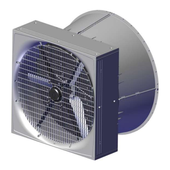
The fan is available in several different versions focusing on low power consumption, as well as standard ver- sions. BD-Blue 130 can be mounted using a cone for optimal air output and reduced power consumption. BD-Blue 130 is specially designed for harsh livestock house environments. This applies to both climatic and electrical influences. -
Page 9: Product Survey
BD-Blue 130 Wall Fans 2 Product survey Technical User Guide... -
Page 10: Bd-Blue 130 Wall Fans
BD-Blue 130 Wall Fans 2.1 BD-Blue 130 wall fans 2.1.1 Type key Fan BD-Blue 130 C -7 DMS 400-3 50/60 3.1A 48900m3h T Fan name Wall Fan BD-Blue Fan size In cm Cone With cone Fan characteristics High flow Low energy... - Page 11 ErP 2015 approved. 60-25-4567 and 60-25-4570 should not be used for negative pressure higher than 80 Pa. 60-25-4577 Fan BD-Blue 130 ON/OFF mot 230-1-50 7.5A 41400m3/h 60-25-4578 Fan BD-Blue 130 ON/OFF mot 230-1-60 7.1A 40400m3/h Fan control method - ON/OFF Safety net outside must be mounted to comply with CE marking, in coun- tries where this is required.
- Page 12 BD-Blue 130 Wall Fans 60-25-4580 Fan BD-Blue 130 ON/OFF mot 400-3-50 3.3A 43500m3/h 60-25-4581 Fan BD-Blue 130 ON/OFF mot 400-3-50 3.3A 43500m3/h T Fan control method - ON/OFF Safety net outside must be mounted to comply with CE marking, in coun- tries where this is required.
- Page 13 BD-Blue 130 Wall Fans 60-25-4586 Fan BD-Blue 130 ON/OFF 400-3-50 3.3A 45100m3/h 435441-02 Fan BD-Blue 130 ON/OFF 400-3-50 3.3A 45100m3/h T 60-25-4587 Fan BD-Blue 130 ON/OFF 400-3-60 3.3A 43200m3/h Fan control method - ON/OFF Safety net outside or motor controlled shutter must be mounted to comply with CE marking, in countries where this is required.
-
Page 14: Accessories
2.2 Accessories 60-25-4459 BD-Blue 130 safety net outside wo/cone, A2 60-25-4458 BD-Blue 130 safety net outside wo/cone, galv The outside safety net is used on BD-Blue 130 without cone where extra safety is required. Supplied with mounting parts. One for each fan. - Page 15 BD-Blue 130 Wall Fans 60-21-1413 BD-Blue 130 insulation plate The insulation plate is used for mounting on a BD-Blue 130 wall fan where extra insulation is necessary. Used to avoid problems with condensation and cold air down draft, espe- cially during the winter.
- Page 16 BD-Blue 130 Wall Fans 435438 BD-Blue 130 support bracket kit f/air shutter Is used to lift air controlled shutter. Can be used on both outside and inside mounted air controlled shutters. Supplied with mounting parts. One for each fan. 81-39-4012 LPC-2 relay module Used for mounting in motor controller/frequency converter, if an alarm out- put is required or reversing of fan is required.
-
Page 17: Mounting Guide
Check that the parts ordered are present and undamaged before starting work. Please read through the entire guide before starting assembly and fitting. If the BD-Blue 130 is installed in areas with risk of ice/snow slide, precautions must be made to avoid damage to the BD-Blue 130. - Page 18 BD-Blue 130 Wall Fans Item Description Foam gun Ladder Jigsaw Socket wrench set Spirit level Try square Technical User Guide...
-
Page 19: Placement Of Bd-Blue 130
Place the insulation of the brickwork all the way in against the BD-Blue 130 and all the way round (as in other building constructions). This way you prevent a cold bridge along the side of BD-Blue 130 from being formed. -
Page 20: Necessary Space For Bd-Blue 130 Without Cone
Recommended measurements for individual mounting of BD-Blue 130 wall fan. (A) Minimum distance is 550 mm, when mounting the LPC motor controller above BD-Blue 130. (B) Minimum distance is 300 mm, when mounting the LPC motor controller between BD-Blue 130. -
Page 21: Measurements For Square Hole In Wall With Cone
3.3.5 Measurements for square hole in wall with cone The dimensions below are given in mm. Recommended measurements for individual mounting of BD-Blue 130 wall fan with mounted cone. (A) Minimum distance is 550 mm, when mounting the LPC motor controller above BD-Blue 130. Technical User Guide... - Page 22 BD-Blue 130 Wall Fans (B) Minimum distance is 300 mm, when mounting the LPC motor controller between BD-Blue 130. Minimum distance from BD-Blue 130 to wall, floor and ceiling Technical User Guide...
-
Page 23: Measure And Saw Out The Holes
BD-Blue 130 Wall Fans 3.4 Measure and saw out the holes Remember to always use a spirit level. Drill 10 mm holes all the way through the wall. Cut the holes. Technical User Guide... -
Page 24: Drainage Holes
Please note that the yellow blanking plug must be at the top. Black If parts of BD-Blue 130 are outside the wall, on the out- side, it is recommended to drill 4 pcs. 5 mm drain holes in the bottom on the four markings. -
Page 25: Mounting In Wall
Lead the cables into the livestock house. Make sure that there is free space for cables. Measure from the top of BD-Blue 130 down (A) make a hole in the wall for the cables as the bending radius of the fan cables is 50 mm. -
Page 26: Mounting With Four Brackets
Blue 130 to fit the wall thickness. Place BD-Blue 130 in the wall. Use wedges to center BD-Blue 130 in the hole. Tip BD-Blue 130 so that the 2 internal brackets can be mounted. The brackets must be in line with wall. Technical User Guide... -
Page 27: Mounting Of Four Angle Bars
BD-Blue 130 Wall Fans 3.6.2 Mounting of four angle bars Mount the 4 angle bars (not supplied) on BD-Blue 130 to fit the wall thickness. Place BD-Blue 130 in the wall. Technical User Guide... -
Page 28: Mounting In Wooden Frame
BD-Blue 130 Wall Fans 3.6.3 Mounting in wooden frame Mount the wooden frame with brackets (not supplied). Place BD-Blue 130 in the wall. Technical User Guide... -
Page 29: Foaming
Remove the net, see section Mounting of inside safety net [} 34](Mounting of inside safety net). Pre-drill 8 holes for mounting on wall. Screw BD-Blue 130 into the wall with 8 screws, with a length of minimum 150 mm. 3.6.4 Foaming Big Dutchman recommends using single-component polyurethane foam or similar. - Page 30 Wet the faces with water from a mist sprayer before pro- ceeding with the foaming. Foam around BD-Blue 130 as shown in the drawing. Foam the wall fan’s corners and approx. 100 mm to each side foam the entire depth of the BD-Blue 130.
- Page 31 BD-Blue 130 Wall Fans In the middle part, it is essential only to foam along the edge, as the foam may otherwise cause BD-Blue 130 to warp. Push the foam in against BD-Blue 130 after the foam has dried a little to allow adequate space for resealing.
-
Page 32: Pointing
BD-Blue 130 Wall Fans 3.6.5 Pointing Big Dutchman recommends Sikaflex 111 Stick & Seal. Complete by applying a sealing edge both internally and externally when the foam is dry. Apply a sealing edge along the angle bracket, as shown in the drawing. -
Page 33: Removing The Transport Bracket
BD-Blue 130 Wall Fans 3.7 Removing the transport bracket On BD-Blue 130 LPC and EL the red transport bracket is located behind the impeller hub. Cut the cable ties. Wrench the transport brackets apart. Remove cable ties and transport brackets from the fan. -
Page 34: Mounting Of Inside Safety Net
BD-Blue 130 Wall Fans 3.8 Mounting of inside safety net Make sure that the net is turned as shown in the draw- ing. Mount the inside safety net on the wall fan using 8 of the screws enclosed (do not tighten to more than 2 Nm). -
Page 35: Mounting Of Air Controlled Shutter
BD-Blue 130 Wall Fans 3.9 Mounting of air controlled shutter Assemble the 4 adapter pieces with a screw in each cor- ner. Mount 12 clips on the adapter frame using 12 screws. Technical User Guide... -
Page 36: Outside Air Controlled Shutter
BD-Blue 130 Wall Fans 3.9.1 Outside air controlled shutter Mounting of BD-Blue 130 support bracket kit for air shut- ter (can be purchased as an accessory) Dismount the 3 PT screws in the center pillar. Push the center pillar slightly out and drill the 3 holes us- ing a 6.5 mm drill. - Page 37 BD-Blue 130 Wall Fans Mount the adapter frame on the fan with 8 screws. Mount the air controlled shutter on the frame by turning the 12 clips. The shutters must turn downwards and turn away from the fan. Technical User Guide...
-
Page 38: Inside Air Controlled Shutter
BD-Blue 130 Wall Fans 3.9.2 Inside air controlled shutter Mounting of BD-Blue 130 support bracket kit for air shut- ter (can be purchased as an accessory) Drill out the 2 markings under the fan using a 6.5 mm drill bit. - Page 39 BD-Blue 130 Wall Fans Mark the 8 holes for the adapter frame. Drill the holes with a 5 mm drill bit. Mount the adapter frame on the fan with 8 screws. Mount the air controlled shutter on the frame by turning the 12 clips.
-
Page 40: Manual Opening Of Motor Controlled Shutter
BD-Blue 130 Wall Fans 3.10 Manual opening of motor controlled shutter Remove the yellow blanking plug. Press on the yellow actuator split with a screwdriver. Technical User Guide... - Page 41 BD-Blue 130 Wall Fans The shutter can now be opened manually. Remember to shut off the fan at the power supply isolator prior to mounting of manual opening. After manual opening. Open the shutters by moving the actuator into its ex- treme position.
- Page 42 BD-Blue 130 Wall Fans Mount the yellow actuator split in the actuator and center column. Mount the rubber plug in the shutter. Technical User Guide...
-
Page 43: Mounting Of Accessories
BD-Blue 130 Wall Fans 3.11 Mounting of accessories 3.11.1 Cone Consists of 4 identical parts. Ensure the tongue and groove at the base are in line. Click the sides together. Hang the cone on the wall fan. Mount the assembled cone on the wall fan using the en- closed screws, female connectors and self-locking nuts. -
Page 44: Outside Safety Net
BD-Blue 130 Wall Fans 3.11.2 Outside safety net If a BD-Blue 130 outside safety net has not been selected, a safety guard must be established. The require- ments of the International Standard for Safety of machinery ISO 13857 shall be complied with. -
Page 45: With Cone
BD-Blue 130 Wall Fans When mounting on an air controlled shutter, pre-drill with a 4.5 mm drill on the side of the shutter. Mount the safety net outside on the air controlled shutter using the clips and screws enclosed (do not tighten to more than 2 Nm). -
Page 46: Insulation Plate
BD-Blue 130 Wall Fans 3.11.3 Insulation plate Mount brackets for the insulation plate on the fan with the 2 screws. Mount the sealing profile on the insulation plate. Drill a 12 mm hole in the center of the insulation plate. -
Page 47: Shading Kit
BD-Blue 130 Wall Fans 3.11.4 Shading kit Mount the top bracket on the plate with 2 screws. Mount 2 bottom brackets on the plate with 2 screws in each. Mount the top bracket on the wall using 2 screws. Mount 2 bottom brackets on the wall fan with 2 screws in each. - Page 48 BD-Blue 130 Wall Fans Screw 2 eye joiners onto the pull rod. Mount eye joiner in top bracket mounted on wall with 1 x M6x20 screw and M6 washer. Mount plate in the bottom bracket on the wall fan. Mount eye joiner in top bracket on plate with split pin.
-
Page 49: Light Trap
BD-Blue 130 Wall Fans 3.11.5 Light trap The sealing profile must be facing BD-Blue 130. Mount the mounting fittings on the wall and on the light trap. Hang the light trap on the wall by engaging the 2 sus- pension brackets. -
Page 50: Installation Guide
In the case of retrofitting fans in an existing house, regardless of ON/OFF fans, LPC fans or frequency convert- ers Big Dutchman recommends that a local expert is involved in checking the electrical installations. The focus should be on cable dimensions, overload protections, local transformers, etc. It is of outmost importance to take the fan specifications into account and, at the same time, ensure that local requirements are fulfilled. -
Page 51: Cabling To Connection Box And Lpc Motor Controller
BD-Blue 130 Wall Fans 4.1.4 Cabling to connection box and LPC motor controller LPC motor controller Power supply isolator Connection box Example of cabling to connection box and LPC motor controller. 4.1.5 Cabeling and placement of LPC motor controller Motor controller must not be built-in or covered and must be mounted on a solid, level surface. -
Page 52: Connection In The Motor Controller/Frequency Converter
BD-Blue 130 Wall Fans 4.1.6 Connection in the motor controller/frequency converter Motor connection terminals (U, V, W, PE) Connection terminals for braking resistor (not used) Connector for optional module Terminal block for programming interface RJ12 programming connector (2 x slave / 1 x master) -
Page 53: Terminals For Power Supply
BD-Blue 130 Wall Fans 4.1.6.1 Terminals for power supply Power supply 3 x 400 V / 3 x 230 V. Power supply 1 x 230 V. Technical User Guide... -
Page 54: Terminals For Power Supply Of Fan
BD-Blue 130 Wall Fans 4.1.6.2 Terminals for power supply of fan Remember to strip the cable so that the protective shield from the fan can be connected to the motor controller during mounting under the rail. Connection from motor controller to fan motor. -
Page 55: Terminals On Relay Module
BD-Blue 130 Wall Fans 4.1.6.4 Terminals on relay module Relay module 445076 can be purchased as accessories. Ground Normal = open Reverse = GND (Short-circuit connection between terminal 15 and GND) Not in use Alarm NO Max. 30 V DC / 24 V AC Alarm NC Mount the relay module as shown in the picture. -
Page 56: Led Indication On The Motor Controller/Frequency Converter
BD-Blue 130 Wall Fans 4.1.7 LED indication on the motor controller/frequency converter The motor controller/frequency converter is equipped with a two-color LED for indication of different operating modes. LED is located on the underside next to the cable glands. • Constantly green when mains voltage is connected. -
Page 57: Emergency Opening For Bd-Blue 130 Actuator - House Controller
Supply voltage too high 4.1.9 Emergency opening for BD-Blue 130 actuator – house controller If emergency unlock for the shutter motor is required, it must be powered by an F6 24V power supply via the computer in the livestock house. -
Page 58: Fan Not Active At Power Failure
BD-Blue 130 Wall Fans +24V-12 +24V-12 is mounted on NO relay in the climate 0V-1 controller. 0V-1 is mounted on NO relay in the climate con- troller. 4.1.9.2 Fan not active at power failure To deactivate the fan at a power failure, select... - Page 59 BD-Blue 130 Wall Fans +24V-12 0V-1 External +24V is mounted on NC relay in the cli- mate controller. 0V is mounted on NO relay in the climate con- troller. Technical User Guide...
-
Page 60: Connection In The Actuator
BD-Blue 130 Wall Fans 4.1.10 Connection in the actuator 4.1.10.1 BD-Blue 130 LPC actuator time-controlled Input signal Open/Closed Flaps Open 45 sec. Close 22 sec. Delayed opening 15 sec. LPC actuator time-controlled 4.1.10.2 BD-Blue 130 LPC actuator stepless Input signal... -
Page 61: Connection Of Extra 24 V Power Supply
BD-Blue 130 Wall Fans 4.1.11 Connection of extra 24 V power supply Internal power supply (A) may only be used to supply factory-installed modules. In case of a greater power consumption than 0.4 A from the main module (B) and 0.4 A from the I/O modules (C) an extra power supply (D) must be used and possibly (E). -
Page 62: Cable Plans And Circuit Diagrams
BD-Blue 130 Wall Fans 4.1.12 Cable plans and circuit diagrams 4.1.12.1 General information about circuit diagrams Symbols are in accordance with the IEC/EN 60617 standard. The classification of the ("letter codes") on the symbols is in accordance with the IEC/EN 81346-2 standard. Reference designations are in accordance with IEC/EN 81346-1:2001 structuring principles and reference designations. -
Page 63: Circuit Diagram For Off/Auto/On Switch
Actuator 4.1.13.2 BD-Blue 130 ON/OFF If using BD-Blue 130 ON/OFF 3x400 V with motor controlled shutter, e.g. for renovation tasks where existing in- stallations are expected to be recycled, this must be solved by contacting Big Dutchman. Technical User Guide... -
Page 64: Circuit Diagram For Emergency Opening
BD-Blue 130 Wall Fans 4.1.14 Circuit diagram for emergency opening 4.1.14.1 BD-Blue 130 LPC Regarding circuit diagram for BD-Blue 130 LPC, see section Emergency opening for BD-Blue 130 actuator – house controller [} 57] 4.1.14.2 BD-Blue 130 ON/OFF Power supply from emergency opening 0V-1 = Q1 terminal in controller. -
Page 65: Bd-Blue 130 Lpc With Reverse (1X230 V)
BD-Blue 130 Wall Fans 4.1.15 BD-Blue 130 LPC with reverse (1x230 V) 4.1.15.1 Cable plan Controller Key breaker LPC fan 1x230 V LPC motor controller Power supply Connection box isolator LPC actuator stepless 4.1.15.2 Circuit diagram Power supply from emergency opening 0V-1 = Q1 terminal in controller. -
Page 66: Bd-Blue 130 Lpc With Alarm Relay (1X230 V)
BD-Blue 130 Wall Fans 4.1.16 BD-Blue 130 LPC with alarm relay (1x230 V) 4.1.16.1 Cable plan Controller Key breaker LPC fan 1x230 V LPC motor controller Power supply Connection box isolator LPC actuator stepless 4.1.16.2 Circuit diagram Power supply from emergency opening 0V-1 = Q1 terminal in controller. -
Page 67: Cl 1400 Lpc 1X230 V Variable On/Off (60-25-4566)
BD-Blue 130 Wall Fans 4.1.17 CL 1400 LPC 1x230 V variable ON/OFF (60-25-4566) 4.1.17.1 Cable plan Controller LPC fan 1x230 V LPC motor controller Power supply Connection box isolator LPC actuator time-controlled 4.1.17.2 Terminals in LPC 1x230 V fan Internal... -
Page 68: Circuit Diagram
BD-Blue 130 Wall Fans 4.1.17.3 Circuit diagram Power supply from emergency opening 0V-1 = Q1 terminal in controller. Power supply from emergency opening 24V-12 = F6 terminal in emergency opening. Example of terminal number For correct connection see the setup menu... -
Page 69: Bd-Blue 130 Lpc 1X230 V Stepless (60-25-4569)
BD-Blue 130 Wall Fans 4.1.18 BD-Blue 130 LPC 1x230 V stepless (60-25-4569) 4.1.18.1 Cable plan Controller LPC fan 1x230 V LPC motor controller Power supply Connection box isolator LPC actuator stepless 4.1.18.2 Terminals in LPC 1x230 V fan Internal External... -
Page 70: Circuit Diagram
BD-Blue 130 Wall Fans 4.1.18.3 Circuit diagram Power supply from emergency opening 0V-1 = Q1 terminal in controller. Power supply from emergency opening 24V-12 = F6 terminal in emergency opening. Example of terminal number For correct connection see the setup menu... -
Page 71: Bd-Blue 130 Lpc 3X400 V Variable On/Off (60-25-4562/60-25-4568)
BD-Blue 130 Wall Fans 4.1.19 BD-Blue 130 LPC 3x400 V variable ON/OFF (60-25-4562/60-25-4568) 4.1.19.1 Cable plan Controller LPC fan 3x400 V LPC motor controller Power supply isolator LPC actuator time-controlled 4.1.19.2 Terminals in LPC 3x400 V fan Internal External Technical User Guide... -
Page 72: Circuit Diagram
BD-Blue 130 Wall Fans 4.1.19.3 Circuit diagram Power supply from emergency opening 0V-1 = Q1 terminal in controller. Power supply from emergency opening 24V-12 = F6 terminal in emergency opening. Example of terminal number For correct connection see the setup menu... -
Page 73: Bd-Blue 130 Lpc 3X400 V With Actuator - Stepless (60-25-4560/60-25-4571)
BD-Blue 130 Wall Fans 4.1.20 BD-Blue 130 LPC 3x400 V with actuator – stepless (60-25-4560/60-25-4571) 4.1.20.1 Cable plan Controller LPC fan 3x400 V LPC motor controller Power supply Connection box isolator LPC actuator stepless 4.1.20.2 Terminals in LPC 3x400 V fan... -
Page 74: Circuit Diagram
BD-Blue 130 Wall Fans 4.1.20.3 Circuit diagram Power supply from emergency opening 0V-1 = Q1 terminal in controller. Power supply from emergency opening 24V-12 = F6 terminal in emergency opening. Example of terminal number For correct connection see the setup menu... -
Page 75: Bd-Blue 130 Lpc 3X230 V Variable On/Off (60-25-4567)
BD-Blue 130 Wall Fans 4.1.21 BD-Blue 130 LPC 3x230 V variable ON/OFF (60-25-4567) 4.1.21.1 Cable plan Controller LPC fan 3x230 V LPC motor controller Power supply isolator LPC actuator time-controlled 4.1.21.2 Terminals in LPC 3x230 V fan Internal External Technical User Guide... -
Page 76: Circuit Diagram
BD-Blue 130 Wall Fans 4.1.21.3 Circuit diagram Power supply from emergency opening 0V-1 = Q1 terminal in controller. Power supply from emergency opening 24V-12 = F6 terminal in emergency opening. Example of terminal number For correct connection see the setup menu... -
Page 77: Bd-Blue 130 Lpc 3X230 V Stepless (60-25-4570)
BD-Blue 130 Wall Fans 4.1.22 BD-Blue 130 LPC 3x230 V stepless (60-25-4570) 4.1.22.1 Cable plan Controller LPC fan 3x230 V LPC motor controller Power supply Connection box isolator LPC actuator stepless 4.1.22.2 Terminals in LPC 3x230 V fan Internal External... -
Page 78: Circuit Diagram
BD-Blue 130 Wall Fans 4.1.22.3 Circuit diagram Power supply from emergency opening 0V-1 = Q1 terminal in controller. Power supply from emergency opening 24V-12 = F6 terminal in emergency opening. Example of terminal number For correct connection see the setup menu... -
Page 79: Bd-Blue 130 El On/Off 1X230 V (60-25-4577/60-25-4578)
BD-Blue 130 Wall Fans 4.1.23 BD-Blue 130 EL ON/OFF 1x230 V (60-25-4577/60-25-4578) 4.1.23.1 Cable plan Wiring box Controller ON/OFF fan Power supply 1x230 V Power supply isolator ON/OFF actuator control box 1x230 V ON/OFF actuator 4.1.23.2 Terminals in ON/OFF 1 x 230 V fan... -
Page 80: On/Off Actuator Control Box
BD-Blue 130 Wall Fans 4.1.23.3 ON/OFF actuator control box 230 V AC N from fan 230 V AC L from supply to fan 24 V DC from power supply 0 V from power supply Blue wire from actuator Brown wire from actuator 4.1.23.4 Circuit diagram... -
Page 81: Bd-Blue 130 El On/Off 3X400 V (60-25-4580)
BD-Blue 130 Wall Fans 4.1.24 BD-Blue 130 EL ON/OFF 3x400 V (60-25-4580) 4.1.24.1 Cable plan Wiring box Controller ON/OFF fan Power supply 3x400 V Power supply isolator ON/OFF actuator control box 1x230 V ON/OFF actuator 4.1.24.2 Terminals in ON/OFF 3x400 V fan... -
Page 82: On/Off Actuator Control Box
Brown wire from actuator 4.1.24.4 Circuit diagram If using BD-Blue 130 ON/OFF 3x400 V with motor controlled shutter, e.g. for renovation tasks where existing in- stallations are expected to be recycled, this must be solved by contacting Big Dutchman. Technical User Guide... -
Page 83: Bd-Blue 130 El On/Off 3X400 V With Thermal Cutout (60-25-4581)
BD-Blue 130 Wall Fans 4.1.25 BD-Blue 130 EL ON/OFF 3x400 V with thermal cutout (60-25-4581) 4.1.25.1 Cable plan Wiring box Controller ON/OFF fan Power supply 3x400 V Power supply isolator ON/OFF actuator control box 1x230 V ON/OFF actuator 4.1.25.2 Terminals in ON/OFF 3x400 V fan with thermal cutout... - Page 84 Brown wire from actuator 4.1.25.4 Circuit diagram If using BD-Blue 130 ON/OFF 3x400 V with motor controlled shutter, e.g. for renovation tasks where existing in- stallations are expected to be recycled, this must be solved by contacting Big Dutchman. Technical User Guide...
-
Page 85: Cable Plan
BD-Blue 130 Wall Fans 4.1.26 BD-Blue 130 EL ON/OFF 3x230 V (60-25-4579) 4.1.26.1 Cable plan Wiring box Controller ON/OFF fan Power supply 3x230 V Power supply isolator ON/OFF actuator control box 1x230 V ON/OFF actuator 4.1.26.2 Terminals in ON/OFF 3x230 V fan... -
Page 86: Circuit Diagram
BD-Blue 130 Wall Fans 4.1.26.3 ON/OFF actuator control box 230 V AC N from fan 230 V AC L from supply to fan 24 V DC from power supply 0 V from power supply Blue wire from actuator Brown wire from actuator 4.1.26.4 Circuit diagram... -
Page 87: Bd-Blue 130 Air On/Off 1X230 V (60-25-4583/60-25-4584)
BD-Blue 130 Wall Fans 4.1.27 BD-Blue 130 AIR ON/OFF 1x230 V (60-25-4583/60-25-4584) 4.1.27.1 Cable plan Controller Wiring box ON/OFF fan 1x230 V Power supply isolator 4.1.27.2 Terminals in ON/OFF 1 x 230 V fan Internal External Technical User Guide... -
Page 88: Circuit Diagram
BD-Blue 130 Wall Fans 4.1.27.3 Circuit diagram Example of terminal number For correct connection see the setup menu Show connection in controller Fan 1x230V Technical User Guide... -
Page 89: Bd-Blue 130 Air On/Off 3X400 V (60-25-4586/60-25-4587)
BD-Blue 130 Wall Fans 4.1.28 BD-Blue 130 AIR ON/OFF 3x400 V (60-25-4586/60-25-4587) 4.1.28.1 Cable plan Controller Wiring box ON/OFF fan 3x400 V Power supply isolator 4.1.28.2 Terminals in ON/OFF 3x400 V fan Internal External Technical User Guide... -
Page 90: Circuit Diagram
BD-Blue 130 Wall Fans 4.1.28.3 Circuit diagram Example of terminal number For correct connection see the setup menu Show connections in the controller Fan 3x400V Technical User Guide... -
Page 91: Bd-Blue 130 Air On/Off 3X400 V With Thermal Cutout (435441-02)
BD-Blue 130 Wall Fans 4.1.29 BD-Blue 130 AIR ON/OFF 3x400 V with thermal cutout (435441-02) 4.1.29.1 Cable plan Controller Wiring box ON/OFF fan 3x400 V Power supply isolator 4.1.29.2 Terminals in ON/OFF 3x400 V fan with thermal cutout External Internal... -
Page 92: Circuit Diagram
BD-Blue 130 Wall Fans 4.1.29.3 Circuit diagram Example of terminal number For correct connection see the setup menu Show connection in controller Fan 3x400V Technical User Guide... -
Page 93: Bd-Blue 130 Air On/Off 3X230 V (60-25-4585)
BD-Blue 130 Wall Fans 4.1.30 BD-Blue 130 AIR ON/OFF 3x230 V (60-25-4585) 4.1.30.1 Cable plan Controller Wiring box ON/OFF fan 3x230 V Power supply isolator 4.1.30.2 Terminals in ON/OFF 3x230 V fan Internal External Technical User Guide... -
Page 94: Circuit Diagram
BD-Blue 130 Wall Fans 4.1.30.3 Circuit Diagram Example of terminal number For correct connection see the setup menu Show connection in controller Fan 3x230V Technical User Guide... -
Page 95: Maintenance Instructions
When washing the inside of the ducts, fan blades must stand still. Remember that fans do not stand high-pressure cleaning. If the inside of the duct needs to be cleaned extra thoroughly Big Dutchman recommends wash- ing from above. When washing the fan, the fan blades must turn around. -
Page 96: Troubleshooting Instructions
BD-Blue 130 Wall Fans 6 Troubleshooting instructions Remember to shut the fan off at the power supply isolator prior to troubleshooting. Troubleshooting shutter system Fault symptom Error Solution Shutter touches the ventilation duct (ob- Remedy the damage. structed). Linkage between flap and actuator faulty. Replace defective parts. - Page 97 BD-Blue 130 Wall Fans Troubleshooting fan motor Fault symptom Error Solution Too high negative pressure in the live- stock house, Fan motor is not run- ning. check the air inlets. AC motor: Check signal to contactor. Control voltage to motor contactor.
-
Page 98: Technical Data
BD-Blue 130 Wall Fans 7 Technical data Air output and efficiency in parenthesis are for wall fans with cone. 7.1 BD-Blue 130 LPC 1x230 V 60-25-4566 BD-Blue 130-6 DMS 60-25-4569 BD-Blue 130-6 0-100% Electrical V AC 230 +/- 10% Rated voltage V AC 175 –... - Page 99 BD-Blue 130 Wall Fans 60-25-4566 BD-Blue 130-6 DMS 60-25-4569 BD-Blue 130-6 0-100% Revolutions per minute 43800 (48500) Air output at 0 Pa 42200 (46300) Air output at -10 Pa 40000 (44100) Air output at -20 Pa 37800 (41600) Air output at -30 Pa...
-
Page 100: Erp/Ecodesign Bd-Blue 130 Lpc 1X230 V
BD-Blue 130 Wall Fans 7.1.1 ErP/Ecodesign BD-Blue 130 LPC 1x230 V Fan type BD-Blue 130-6 DMS BD-Blue 130-6 0-100% ErP 2015 (N40) Ecodesign 57.9 Efficiency classification 52.4 Efficiency (η) Measurement setup Static Fan efficiency VSD required 2020 Year of production... -
Page 101: Bd-Blue 130 Lpc 3X400 V
BD-Blue 130 Wall Fans 7.2 BD-Blue 130 LPC 3x400 V 60-25-4562 BD-Blue 130-7 60-25-4568 BD-Blue 130-6 DMS / 60-25-4560 BD-Blue DMS / 60-25-4571 BD-Blue 130-7 0-100% 130-6 0-100% Electrical V AC 400 +10% / -8% 400 +/- 10% Rated voltage V AC 280 –... - Page 102 BD-Blue 130 Wall Fans 60-25-4562 BD-Blue 130-7 60-25-4568 BD-Blue 130-6 DMS / 60-25-4560 BD-Blue DMS / 60-25-4571 BD-Blue 130-7 0-100% 130-6 0-100% 43100 (46900) 38000 (41600) Air output at -30 Pa 41100 (44900) 35500 (39500) Air output at -40 Pa...
-
Page 103: Erp/Ecodesign Bf 50 Lpc 3X400 V
BD-Blue 130 Wall Fans 7.2.1 ErP/Ecodesign BF 50 LPC 3x400 V Fan type BD-Blue 130-7 DMS / BD-Blue BD-Blue 130-6 DMS / BD-Blue 130-7 0-100% 130-6 0-100% ErP 2015 (N40) Ecodesign 59.4 60.3 Efficiency classification 54.6 54.7 Efficiency (η) Measurement setup... -
Page 104: Bd-Blue 130 Lpc 3X230 V
BD-Blue 130 Wall Fans 7.3 BD-Blue 130 LPC 3x230 V 60-25-4567 BD-Blue 130-6 DMS 60-25-4570 BD-Blue 130-6 0-100% Electrical V AC 200 - 230 +/- 10% Rated voltage V AC 175 – 280 Operating voltage For supply voltages below the rated voltage range, a reduction of the fan’s RPM may occur depending on the load and ambient... - Page 105 BD-Blue 130 Wall Fans 60-25-4567 BD-Blue 130-6 DMS 60-25-4570 BD-Blue 130-6 0-100% 42000 (46300) Air output at -10 Pa 40200 (44400) Air output at -20 Pa 37900 (41600) Air output at -30 Pa 35400 (39000) Air output at -40 Pa...
-
Page 106: Erp/Ecodesign Bd-Blue 130 Lpc 3X230 V
BD-Blue 130 Wall Fans 7.3.1 ErP/Ecodesign BD-Blue 130 LPC 3x230 V Fan type BD-Blue 130-6 DMS BD-Blue 130-6 0-100% ErP 2015 (N40) Ecodesign 59.9 Efficiency classification 54.3 Efficiency (η) Measurement setup Static Fan efficiency VSD required 2020 Year of production... - Page 107 BD-Blue 130 Wall Fans 7.4 BD-Blue 130 ON/OFF EL 1x230 V 60-25-4577 60-25-4578 BD-Blue 130 ON/OFF mot 1x230 V BD-Blue 130 ON/OFF mot 1x230 V Electrical V AC 230 +/-10% Rated voltage V AC 207 – 253 Operating voltage Frequency Max.
- Page 108 Protection class dB (A) Fan noise, outside (2 m, 45 degrees) Shipment 75000 Shipping weight 7.4.1 ErP/Ecodesign BD-Blue 130 ON/OFF EL 1x230 V Fan type BD-Blue 130 ON/OFF mot BD-Blue 130 ON/OFF mot 1x230 V 1x230 V ErP 2015 (N40) Ecodesign 46.6...
- Page 109 BD-Blue 130 Wall Fans 7.5 BD-Blue 130 ON/OFF EL 3x400 V 60-25-4580 60-25-4581 BD-Blue 130 ON/OFF mot 3x400 V BD-Blue 130 ON/OFF mot 3x400 V w/thermal cutout Electrical V AC 400 +/-10% Rated voltage V AC 360 – 440 Operating voltage Frequency Max.
- Page 110 (A) Fan noise, outside (2 m, 45 degrees) Shipment 75000 Shipping weight 7.5.1 ErP/Ecodesign BD-Blue 130 ON/OFF EL 3x400 V Fan type BD-Blue 130 ON/OFF mot BD-Blue 130 ON/OFF mot 3x400 V 3x400 V w/thermal cutout ErP 2015 (N40) Ecodesign 48.9...
- Page 111 BD-Blue 130 Wall Fans 7.6 BD-Blue 130 ON/OFF EL 3x230 V/3x200 V 60-25-4579 Fan BD-Blue 130 ON/OFF mot Fan BD-Blue 130 ON/OFF mot 230-3-60 5.6A 42400m3/h 200-3-60 5.6A 42400m3/h Electrical V AC 230 +/-10% 200 +10/-5% Rated voltage V AC 207 –...
- Page 112 IP 65 Protection class dB (A) Fan noise, outside (2 m, 45 degrees) Shipment 75000 Shipping weight 7.6.1 ErP/Ecodesign BD-Blue 130 ON/OFF EL 3x230 V Fan type BD-Blue 130 ON/OFF mot 3x230 V ErP 2015 (N58) Ecodesign 51.1 Efficiency classification 49.3 Efficiency (η)
- Page 113 BD-Blue 130 Wall Fans 7.7 BD-Blue 130 ON/OFF AIR 1x230 V 60-25-4583 60-25-4584 BD-Blue 130 ON/OFF 1x230 V BD-Blue 130 ON/OFF 1x230 V Electrical V AC 230 +/-10% Rated voltage V AC 207 – 253 Operating voltage Frequency Max. power consumption...
- Page 114 Air shutter inside Air shutter outside Shipment 72000 Shipping weight 7.7.1 ErP/Ecodesign BD-Blue 130 ON/OFF AIR 1x230 V Fan type BD-Blue 130 ON/OFF 1x230 V BD-Blue 130 ON/OFF 1x230 V ErP 2015 (N40) Ecodesign 46.6 50.2 Efficiency classification 44.4 48.3 Efficiency (η)
- Page 115 BD-Blue 130 Wall Fans 7.8 BD-Blue 130 ON/OFF AIR 3x400 V 60-25-4586 435441-02 60-25-4587 BD-Blue 130 ON/ BD-Blue 130 ON/ BD-Blue 130 ON/ OFF 3x400 V OFF 3x400 V w/ther- OFF 3x400 V mal cutout Electrical V AC 400 +/-10%...
-
Page 116: Bd-Blue 130 On/Off El 1X230 V
BD-Blue 130 Wall Fans 60-25-4586 435441-02 60-25-4587 BD-Blue 130 ON/ BD-Blue 130 ON/ BD-Blue 130 ON/ OFF 3x400 V OFF 3x400 V w/ther- OFF 3x400 V mal cutout °C (°F) ÷ 40 to + 50 (÷ 40 to 122) Start temperature °C (°F) -
Page 117: Erp/Ecodesign Bd-Blue 130 On/Off El 3X400 V
BD-Blue 130 Wall Fans 7.8.1 ErP/Ecodesign BD-Blue 130 ON/OFF AIR 3x400 V Fan type BD-Blue 130 ON/OFF BD-Blue 130 ON/OFF BD-Blue 130 ON/OFF 3x400 V 3x400 V w/thermal 3x400 V cutout ErP 2015 (N40) Ecodesign 48.9 50.4 Efficiency classifica- tion 47.0... - Page 118 BD-Blue 130 Wall Fans 7.9 BD-Blue 130 ON/OFF AIR 3x230 V/3x200 V 60-25-4585 Fan BD-Blue 130 ON/OFF Fan BD-Blue 130 ON/OFF 230-3-60 5.6A 43300m3/h 200-3-60 5.6A 43300m3/h Electrical V AC 230 +/-10% 200 +10/-5% Rated voltage V AC 207 – 253 190 –...
- Page 119 Fan noise, outside (2 m, 45 degrees) Air shutter inside Air shutter outside Shipment 72000 Shipping weight 7.9.1 ErP/Ecodesign BD-Blue 130 ON/OFF AIR 3x230 V Fan type BD-Blue 130 ON/OFF 3x230 V ErP 2015 (N40) Ecodesign 51.1 Efficiency classification 49.3 Efficiency (η)
-
Page 120: Actuators
BD-Blue 130 Wall Fans 7.10 Actuators 524116 524118 524117 LPC actuator time- LPC actuator stepless ON/OFF actuator controlled Electrical V DC Rated voltage V DC 16 - 28 16 - 28 16 – 28 Operating voltage Max. current consump- tion at 24 V DC power supply pcs. - Page 121 BD-Blue 130 Wall Fans 7.11 Metal and plastic parts Mechanical Material plastic PP T20 BD-Blue 130 box PP T20 BD-Blue 130 top and bottom panel PP T20 BD-Blue 130 side panel PP T20 BD-Blue 130 cone PP GF30 BD-Blue 130 center pillar...
-
Page 122: Light Traps
BD-Blue 130 Wall Fans 7.12 Light traps 50ʺ light trap brown out 50ʺ light trap black out Mechanical Material RAL 9005 Color Fan output The light trap reduces the air output The light trap reduces the air output With cone... -
Page 123: Number Of Wall Fans In A Container
BD-Blue 130 Wall Fans 7.13 Number of wall fans in a container Number of wall fans in a container Motor controlled shutter Air controlled shutter 20' DC BD-Blue 130 without cone BD-Blue 130 with cone 40' HC BD-Blue 130 without cone... -
Page 124: Dimensioned Sketch
BD-Blue 130 Wall Fans 8 Dimensioned sketch 8.1 BD-Blue 130 BD-Blue 130 without cone BD-Blue 130 with cone Technical User Guide... -
Page 125: Lpc Motor Controller
BD-Blue 130 Wall Fans BD-Blue 130 with outside shutter BD-Blue 130 with inside shutter 8.2 LPC motor controller 1x230 V 3x230 V and 3x400 V Technical User Guide... - Page 126 BD-Blue 130 Wall Fans 8.3 Light trap 50ʺ brown out / 50ʺ black out 8.4 Outside safety net Outside safety net Technical User Guide...
- Page 128 Big Dutchman International GmbH • Calveslage • Auf der lage 2 • 49377 Vechta; Germany Tel. +49(0)4447/801-0 • Fax +49(0)4447/801-237 • big@bigdutchman.com...
Need help?
Do you have a question about the BD-Blue 130 and is the answer not in the manual?
Questions and answers
How close the actuator with a battery