Table of Contents
Advertisement
Quick Links
Advertisement
Table of Contents

Related Manuals for Kipp & Zonen CV 2

Summary of Contents for Kipp & Zonen CV 2
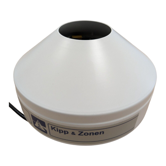
- Page 1 Kipp & Zonen INSTRUCTION MANUAL VENTILATION UNIT...
-
Page 2: Important User Information
All rights reserved. No part of this publication may be reproduced, stored in a retrieval system or transmitted in any form or by any means, without permission in written form from the company. Manual version 1203 INSTRUCTION MANUAL CV 2... -
Page 3: Ce Declaration Of Conformity
To which this declaration relates is in conformity with the following standards Imissions EN 50082-1 Group standard Emissions EN 50081-1 Group standard EN 55022 Safety standard IEC 1010-1 Following the provisions of the directive B.A.H. Dieterink President KIPP & ZONEN B.V. INSTRUCTION MANUAL CV 2... -
Page 4: Table Of Contents
4.1 General..................11 4.2 Measuring global radiation ............12 4.3 Measuring diffuse radiation ............13 INSTALLATION OF THE POWER SUPPLY FOR CV 2..15 MAINTENANCE AND OPERATING ........17 TROUBLE SHOOTING ............19 PART NUMBERS / SPARE PARTS / OPTIONS ..... 21... - Page 5 INSTRUCTION MANUAL CV 2...
-
Page 6: General Information
1 K, offset problems are not significant. The ventilation system CV 2 is meant to be used with the Kipp & Zonen pyranometers (CM 11, CM 6B, CM 21 and CM 22) and with radiation sensors with equal dimensions like the pyrgeometers (CG 1 and CG 4) and the UV- radiometers (CUVA 1, CUVB 1, CUV 3). - Page 7 INSTRUCTION MANUAL CV 2...
-
Page 8: Delivery Complete Ventilation System Cv 2
DELIVERY COMPLETE VENTILATION SYSTEM CV 2 DELIVERY COMPLETE VENTILATION SYSTEM CV 2 CV 2 with heater 0349 901 Power supply for CV 2 (with heater) 0349 401 2 x bolt M6 x 90 2146 824 2 x bolt M5 x 50... - Page 9 INSTRUCTION MANUAL CV 2...
-
Page 10: Specifications Cv 2
Offset caused by heater (10 W) < 1 W/m using Pyranometer CM 11 Cable length 10 m. Power required 12 Volt DC, 1,25 A (with 10 W heater) Figure 3.1 CV 2 outline dimensions in mm INSTRUCTION MANUAL CV 2... - Page 11 INSTRUCTION MANUAL CV 2...
-
Page 12: Installation Of The Cv 2
CV 2. After levelling the CV 2 can be fixated to the floor or plate using the 2 M6 x 90 screws. The cable of the radiometer can be slit through the opening of the side of the CV 2 base plate. - Page 13 Figure 4.1.2 The 2 special screws to lock the cover. INSTRUCTION MANUAL CV 2...
-
Page 14: Measuring Global Radiation
INSTALLATION OF THE CV 2 Measuring global radiation The blower unit can be installed on a flat plate, using the CV 2 levelling screws. Figures 4.2.1 and 4.2.2 refer to this situation. If problems with snow build-up are expected, a hole can be made in the plate directly under the ventilator. - Page 15 (see figure 4.3.1) No special precautions are necessary. Instead of the radiometer support the CV 2 will give the radiometer the correct height. The mounting holes to fixate the CV 2 are present on the 2AP mounting plate. Further details on how to mount the CV 2, radiometer combination on the tracker will be given in the 2AP manual.
-
Page 16: Installation Of The Power Supply For Cv 2
INSTALLATION OF THE POWER SUPPLY FOR CV 2 INSTALLATION OF THE POWER SUPPLY FOR CV 2 The optional power supply unit (figure 5.1) is meant for indoor installation only. The dimensions are (W x D x H) 134 x 80 x 53,5 mm. - Page 17 INSTALLATION OF THE POWER SUPPLY FOR CV 2 The CV 2 has a 10 meter 4 wire shielded cable to connect to the power supply The Connection between the CV 2 cable and the adapter cable can be made with any standard connection terminal block (e.g. like the one that is used inside the CV 2 connection box, see figure 5.2).
-
Page 18: Maintenance And Operating
(see figure 6.1). The air filter is located on the bottom of the CV 2. The filter can be checked and changed by removing the cover from the filter by pulling it down with two hands on both sides of the CV 2. - Page 19 INSTRUCTION MANUAL CV 2...
-
Page 20: Trouble Shooting
Check impedance Electrical connections Ω R1 to R4 = 4 x 15 Ventilator does not Power supply Check voltage work Obstruction Check interior See figure 5.2 and 6.1 for locations to check. INSTRUCTION MANUAL CV 2... - Page 21 INSTRUCTION MANUAL CV 2...
-
Page 22: Part Numbers / Spare Parts / Options
2132 170 Spare air filters (set of 5) 2682 916 Power supply for CV 2 with heater 0349 401 The ventilator and heating elements are specially prepared for outdoor use. Please ask Kipp & Zonen in case of repair or replacement. - Page 23 INSTRUCTION MANUAL CV 2...
- Page 24 C ustomer S upport Our customer support Für Servicearbeiten und Notre service 'Support Clientèle' remains at your disposal Kalibrierung, Verbrauchs- reste à votre entière disposition for any maintenance or material und Ersatzteile pour tout problème de maintenance, réparation ou repair, calibration, steht Ihnen unsere supplies and spares.
Need help?
Do you have a question about the CV 2 and is the answer not in the manual?
Questions and answers