Advertisement
Quick Links
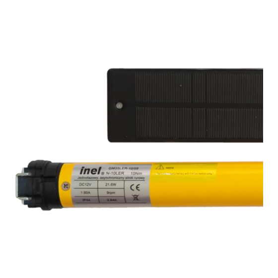
Drive installation and operation manual, type: GM
DC drive GM35LER-10/09 (N-10LER) with overload detection,
integrated radio and battery charged by solar panel.
Drive with integrated battery, recharged by energy from a solar
panel. The drive is designed for wireless control of guards. In order
for the motor to work correctly with the roller shutter, it is necessary
to use hanger-locks on the winding tube and stoppers in the bottom
bar. The stoppers should be placed as close to the guides as possible
to improve comfort. A sill must be fitted to the window and the length
of the guard must match the length of the guides.
Before installing the drive, connect it to the charger and
charge the battery for 6 hours.
Locking hanger – assembly guidelines
The shutter height should be selected to make sure that with the shutter
closed the uppermost slat of the curtain protrudes from the guide up to
half of its height at maximum.
Excessive shutter height may cause faulty operation or even damage. The
hanger length and shutter height must be selected so that the hanger
presses on the first slat of the curtain downwards the guide.
1 Safety instructions
1.1 Basic guidelines
The drive is handed over in a condition for safe installation and use,
provided that all instructions in the operating manual are complied with.
Conversion or changes to the drive are not permitted. Warranty repairs
may only be carried out by the manufacturer. Only original spare parts
and accessories should be used for post-warranty repairs. Safe operation
of the supplied drive is only guaranteed when used in accordance with the
manufacturer's specifications. The limits given in the technical data must
not be exceeded under any circumstances.
1.2 Supplementary safety provisions
Important safety and accident prevention regulations must be observed
when installing, commissioning and maintaining the drive. The following
provisions require special attention:
1. Fire regulations.
2. Accident prevention regulations.
1.3 General comments on hazards and safety measures
The comments listed are general guidelines when using INEL equipment
in combination with other equipment. These indications must be strictly
adhered to when installing and operating the equipment.
Original instructions PL
Model:
GM35LER-10/09 (N-10LER)
• Before installing the drive and setting the end positions, check the
tightening of all screw connections.
• The applicable safety and accident prevention regulations must be
observed.
• Wires and cables should be checked regularly for insulation damage
and conductor continuity.
• If the cables are found to be damaged, the damaged cables must be
replaced after the power supply has been switched off immediately.
1.4 Warning
• Do not let children play with the control devices.
• Keep remote control devices out of the reach of children.
• Watch the roller shutter moving and keep bystanders clear until it is
fully open or closed.
• Users of the roller shutter must be trained and instructed on how to
operate the roller shutter and on the dangers involved in its use. People
can be considered trained if the employer, administrator or owner has
allowed them to operate the roller shutter and instructed them on how
to use it.
2
Assembly instructions
2.1 Safety rules
▪ Inst Installation of the drive must only be carried out by suitably
qualified persons.
▪ The weight of the roller shutter must not exceed the load capacity of
the drive as indicated in the selection table (table available at
www.inel.gda.pl).
▪ The proper way of laying the cable (loop facing downwards) further
protects the drive from possible water damage.
▪ Do not drill holes in the motor housing.
▪ Protect the motor from contact with any fluid.
▪ Avoid crushing, impact to the motor and protect the motor from falling.
2.2 Assembly of the drive
• Attach the mounting bracket (A) to the side of the roller shutter box,
connect the adapter (D) to the motor drive ring.
• Place the dog (E)supplied with the motor on the motor shaft and secure
it with the pin (F), then slide the entire drive into the winding tube (G).
• Connect the winding tube and the drive dog with screws or rivets (H).
Figure 1
Figure 2
Advertisement

Subscribe to Our Youtube Channel
Related Manuals for Inel GM35LER-10/09


Summary of Contents for Inel GM35LER-10/09
- Page 1 2. Accident prevention regulations. 1.3 General comments on hazards and safety measures The comments listed are general guidelines when using INEL equipment in combination with other equipment. These indications must be strictly adhered to when installing and operating the equipment.
- Page 2 PIL-19/99DLT, PIL-19/99MMT, PIL-01PT. Change of direction of rotation Use remote controls from Inel's extensive range (except key fobs) to control the drive. The remote control must be registered. Registering the If, after pressing the key ∧ the roller shutter moves upwards, the direction...
- Page 3 The full text of the EU Declaration of Conformity is available at the drive is installed, the battery is recharged with electricity from the solar following internet address: www.inel.gda.pl panel. If there is a long period between purchase and installation of the drive, the battery should be charged using a charger (sold separately by the manufacturer).
- Page 4 The wires should be attached to the side of the box so that they do not come into contact with moving parts. Przedsiębiorstwo Informatyczno-Elektroniczne INEL Sp. z o.o., ul. Mostowa 1, 80-778 Gdańsk, Poland inel@inel.gda.pl www.inel.gda.pl...
Need help?
Do you have a question about the GM35LER-10/09 and is the answer not in the manual?
Questions and answers