Table of Contents
Advertisement
Quick Links
Certifications:
ISO 9001:2008
EN ISO 13485:2003
USER MANUAL
Leading Through Innovation
Recorders & Medicare Systems (P) Ltd.
H.O. & Works:
196, Industrial Area, Phase 1, Panchkula-134113(Haryana), INDIA.
Ph.: +91-172-2564196, 2565196, Fax: +91-172-2566196
Regd. Office:
181/5, Industrial Area, Phase 1, Chandigarh-160002, INDIA.
Website: www.rmsindia.com, e-mail:
helpdesk@rmsindia.com
Advertisement
Table of Contents

Subscribe to Our Youtube Channel
Related Manuals for RMS Msximus 32


Summary of Contents for RMS Msximus 32
- Page 1 Certifications: ISO 9001:2008 EN ISO 13485:2003 USER MANUAL Leading Through Innovation Recorders & Medicare Systems (P) Ltd. H.O. & Works: 196, Industrial Area, Phase 1, Panchkula-134113(Haryana), INDIA. Ph.: +91-172-2564196, 2565196, Fax: +91-172-2566196 Regd. Office: 181/5, Industrial Area, Phase 1, Chandigarh-160002, INDIA. Website: www.rmsindia.com, e-mail: helpdesk@rmsindia.com...
- Page 3 All rights reserved. No parts of this manual may be reproduced in any form without the express written permission of RMS. Recorders & Medicare Systems (P) Ltd. (RMS) makes no representations or warranties with respect to the contents hereof. In addition, information contained herein is subject to change without notice.
-
Page 4: Intended Use
USER MANUAL INTRODUCTION 1. INTRODUCTION 1.1 SCOPE An Electroencephalograph (EEG) measures & records the electrical activity of brain by using sensors (electrodes) attached to head and this raw signal gets amplified and sent to (personal computer) through USB for analysis .The PC records the brain’s electrical activity & display’s on the screen. - Page 5 USER MANUAL INTRODUCTION • Scrolling (Left to Right & Right to Left) and page wise analysis. • Print Preview for analysis, Brain maps etc. • Fully Synchronized video with data. • Achieving data to CD/DVD hard disc. • Drag and drop facility for event and comments. •...
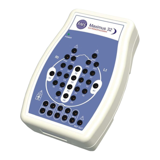
- Page 6 USER MANUAL INTRODUCTION 1.4 MACHINE & ITS PARTS • HEAD BOX FRONT VIEW Below picture shows the Head Box which collect the – various electrical signals from patient’s brain through the electrodes. Power Bottom View Top View Side View • TWO MODE’S SUPPLY SWITCH- This switch is used to run machine in two different supply modes.
- Page 7 The purpose of this external DC switch connected to the head box is to enable recording of events without involving the RMS Maximus EEG software entirely. The patient, the technician or a non-technical person present with patient can press this button when the need arises.
-
Page 8: Block Diagram
USER MANUAL INTRODUCTION 1.5 BLOCK DIAGRAM The below figure shows the basics of system block diagram of MAXIMUS 32 Channel. The microvolt signals are received from the patient via the 32-electrodes placed on the scalp of the patient and sent to pre-amplifier stages for strengthening of weak signals and reducing noise due to offset potentials and common mode signals. - Page 9 USER MANUAL INTRODUCTION Event Respiration Auxiliary Marker Module Module Multiplexer Analog to Digital Converter Amplifier & Digital to Analog Filtration Converter Module 32 Bit 24 Channel Microcontroller Photic Electrodes ISOLATOR Flash 5 V Supply USB Isolator Adaptor Bo Isolation Personal Computer Main Maximus 32 Block Diagram...
- Page 10 Ending the EEG session. 1. THE EEG ACQUISITION For acquiring the EEG waveforms, you must connect the hardware with RMS Maximus-32 software and then initiate the acquisition. The RMS Maximus software acquires digitalized EEG signals from the electrodes placed on the skull of the patient. The EEG waveform display on the application main screen.
- Page 11 USER MANUAL ACQUISITION from the hardware displays on the screen. If the video monitoring facility is used, the video also displays. Make sure the electrode impedance is within limit. By checking the electrode impedance you can ensure that the electrodes are properly attached to the scalp. If the photic stimulation is required start the stimulation at the appropriate time.
-
Page 12: Installation Procedure
Put Software CD in the Computer. The Auto run CD automatically opens the following contents. Choose whether you want to install the RMS Maximus Software or to Explore RMS Maximus Drivers Location or to Install Video Compression. To install the RMS Maximus... - Page 13 Once you successfully installed the RMS Maximus-32 EEG, you can start using it. It is recommended that you familiarize yourself with its user interface before you start using the RMS Maximums-32 EEG.
- Page 14 The user interface of the two modules of the RMS Maximus-32 EEG are however similar with some exceptions, as discussed in the relevant chapters. These modules also share many common features.
- Page 15 USER MANUAL ACQUISITION 2.2.4 ACQUISITION TOOL BAR – Pause New Patient Record Patient Information Stop Calibration Play Impedance Check Printer Mark Eyes Open Photic Eyes Close Drowsy Seizure Awake Movement Asleep Jerk Capture Photo Sensitivity + Video On/Off Sensitivity - Notch Sweep - Sweep +...
- Page 16 USER MANUAL ACQUISITION 14. ASLEEP – Refer to the Events in the Menu Bar. 15. JERK – Refer to the Events in the Menu Bar. 16. MOVEMENT – Refer to the Events in the Menu Bar. 17. SEIZURE – Refer to the Events in the Menu Bar. 18.
- Page 17 USER MANUAL ANALYSIS To open Analysis SW, double click on the ‘Analysis’ icon on desktop. Title Standard Menu Bar Toolbar Active Screen Status Bar Waveform display section Montage Bar Figure: Analysis screen Title BAR The title bar shows the Patient ID, Age, Recording Time, Test Time, channels and No. of pages.
- Page 18 USER MANUAL REPORTING 4. REPORTING 4.1 EXPLANATION OF REPORTS Any notes or Comments entered by the doctor can be seen in the report. Click on the Analysis option. Select patient from option Patient Info and then click on the Print Report button.
-
Page 19: Maintenance
5.1 MAINTENANCE & CLEANING GENERAL MAINTENANCE OF THE EQUIPMENT It is important to maintain the RMS EEG equipment so it performs as desired and provides accurate output. Following is the list of various tips for properly maintaining your RMS EEG system. -
Page 20: Corrective Maintenance
In case of detecting a break-down in the system which impedes its normal use, disconnect the device from power supply and contact the nearest RMS customer support location. Specify as much details as possible the type of problem detected. - Page 21 USER MANUAL APPENDIX A1. SCREEN SYMBOLS – S.No ICON SYMBOL S.No. ICON SYMBOL Load Patient Patient information Search event Enter Patient Play information Impedance Record Calibration Stop Open Next Page (F2) Print Auto Fwd Impedance Next Event Seizure Zoom Insert tab or page m Analyse Mark attention Measurements...
-
Page 22: Abbreviations Used
USER MANUAL APPENDIX Sen(+F5) Freeze waves Sen(-F5) Load Previous Patient Sweep(-F6) Load Next Patient Sweep(+F6) Switch Mode(ASIS or Normal) LF(+/_F7) ABBREVIATIONS USED- Identification number High Filter mm/sec Millimeter per second Electroencephalograph Low Filter Acquisition Electromyography Seconds Sens Sensitivity µv/mm Microvolt/millimeter Channel Freq. -
Page 23: Technical Specifications
USER MANUAL AP PENDIX A.4 TECHNICAL SPECIFICATIONS General Specifications Type of protection Class II A Degree of protection Type BF Computer Communication Interface Computer Configuration IBM compatible(Core 2 duo latest 2.4GHz) Operating System Windows XP 1 GB (Min.) Display Format 32 Channel EEG Unit A/D Resolution... - Page 24 USER MANUAL AP PENDIX Voltage Resolution < 0.3 µV Noise Level < 0.3 µV RMS Recording & Printing Recorder Windows Compatible inkjet/LaserJet. Power Supply USB Power Requirement 5V USB ,500 mA Adaptor Power Supply (optional) ~ 220 - 320V, 50Hz ± 10%...
-
Page 25: Safety Instructions
USER MANUAL APPENDIX ACCESSORIES Accessories Quantity Photic Flash USB Cable Micro pore Tape Earthing Cord Electrode Type-I EG-EGS Electrode Type-II GND -EGS Electrode Type-III JUMPER-I -EGS Electrode Type-IV Jumper-Ii-EGS Respiration Transducer (OPTIONAL) Software CD Maximus Quick Installation Guide Event Marker Recording Paste Carry Bag Cleaning Brush... - Page 26 USER MANUAL APPENDIX the following constraints: They shall not be placed on the floor. Additional multiple portable socket outlets or extension cords shall not be connected to the system. They shall only be used for supplying power to the equipment which is intended to form part of the system.
-
Page 27: Warranty Card
For other equipments, viz. EEG, EMG, Stress Test System, X-Ray machines, Polyrite etc., RMS will depute its engineer within a reasonable time to repair the machine. Although most of the repair work will be carried out at customer’s premises, certain parts requiring specialized goods and equipments will have to be sent to our Works at Panchkula, Haryana for repairs. - Page 28 - Where the machine has been installed, serviced, repaired, opened or tampered by any unauthorized person. - Damage caused by the use of Non- RMS supplies, Parts, Consumables & accessories. - Damage resulting from modification and integration with other products.
- Page 29 For other equipments, viz. EEG, EMG, Stress Test System, X-Ray machines, Polyrite etc., RMS will depute its engineer within a reasonable time to repair the machine. Although most of the repair work will be carried out at customer’s premises, certain parts requiring specialized goods and equipments will have to be sent to our Works at Panchkula, Haryana for repairs.
- Page 30 - Where the machine has been installed, serviced, repaired, opened or tampered by any unauthorized person. - Damage caused by the use of Non- RMS supplies, Parts, Consumables & accessories. - Damage resulting from modification and integration with other products.
-
Page 31: Customer Responsibility
ATTENTION RMS makes no warranty of any kind, expressed or implied, including, b RMS makes no warranty of any kind, expressed or implied, including, bu ited to, the ut not limited to, the implied warranties of merchantability and fitness for a particular purpos implied warranties of merchantability and fitness for a particular purpose ssumes no e. - Page 32 If the machine is not functioning properly, do not operate it until all necessary repairs have been made and unit it is tested for proper functioning in accordance with the RMS published specifications. It is recommended that all repairs be performed by qualified service representative only.
- Page 33 Recorders & Medicare Systems (P) Ltd. H.O. & Works: 196, Industrial Area, Phase 1, Panchkula-134113 (Haryana), INDIA. Ph.: +91-172-2564196, 2565196, Fax: +91-172-2566196 Regd. Office: 181/5, Industrial Area, Phase 1, Chandigarh-160002, INDIA. Website: www.rmsindia.com, e-mail: helpdesk@rmsindia.com...
Need help?
Do you have a question about the Msximus 32 and is the answer not in the manual?
Questions and answers