Table of Contents
Advertisement
Quick Links
Company confidential
User manual
DA9155M Getting Started with
Evaluation Board
UM-PM-010
Abstract
This document describes the hardware and software used by Dialog Semiconductor to test and
evaluate the DA9155M slave battery charger.
The hardware solution is based on PCB numbered 287-06-A.
The software uses a PC operating Windows 2000/XP/Vista/Windows 7 ™ with USB (1.1, 2.0 or 3.0)
interface.
The software permits configuration of the device using one pre-defined templates, read and
operations to all control registers while monitoring device status.
The section 'Quick Start Tutorial' provides an abbreviated quick start guide with a practical
configuration example on how to run the evaluation kit.
Advertisement
Table of Contents

Related Manuals for Dialog Semiconductor DA9155M

Summary of Contents for Dialog Semiconductor DA9155M
-
Page 1: Abstract
Evaluation Board UM-PM-010 Abstract This document describes the hardware and software used by Dialog Semiconductor to test and evaluate the DA9155M slave battery charger. The hardware solution is based on PCB numbered 287-06-A. The software uses a PC operating Windows 2000/XP/Vista/Windows 7 ™ with USB (1.1, 2.0 or 3.0) interface. -
Page 2: Table Of Contents
Figure 7: DIO and DA9155M Performance board ................. 9 Figure 8: DA9155M Evaluation GUI Installation File ................11 Figure 9: DA9155M GUI Software Licensing and Installation ............. 11 Figure 10: DA9155M GUI Installation Path ..................11 Figure 11: GUI Overview Screen ......................12 Figure 12: Active Communication Indicator .................. -
Page 3: Tables
UM-PM-010 DA9155M Getting Started with Evaluation Board Company confidential Tables Table 1: DA9155M Performance Board recommended operating conditions ........5 Table 2: DA9155M Performance Board overview and descriptions............6 Table 3: List of hardware ........................10 Terms and definitions Digital Audio Interface... -
Page 4: Introduction
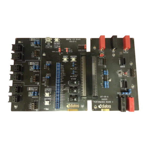
The performance board includes an interface connector to the communication board referred as the Digital I/O (DIO) board. This DIO board connects the DA9155M to a computer via USB-to-I2C, for status monitoring and control using the DA9155M Graphical User Interface (GUI). -
Page 5: Board Recommended Operating Conditions
Company confidential Board recommended operating conditions Table 1 lists the recommended operating conditions of the DA9155M Performance board. Stressing the board beyond these ratings may cause permanent damage to the board. Table 1: DA9155M Performance Board recommended operating conditions Parameter... -
Page 6: Da9155M Performance Board Hardware
UM-PM-010 DA9155M Getting Started with Evaluation Board Company confidential DA9155M Performance Board Hardware The DA9155M board functional overview is shown in Figure 2. The board functionality can be broken down into the following functions: Figure 2: Functional overview Table 2: DA9155M Performance Board overview and descriptions Section No. -
Page 7: Da9155M Slave Charger Layout
[Ref 1] and also shown in Figure 3 below. The same layout guidelines were followed and implemented for the DA9155M Performance Board, with the exception of the footprint for additional output capacitors are included in the board for experimentation purposes. -
Page 8: Slave Charger Multi-Test Point J10 Connector
○ Input voltage VIN sense ○ Output voltage VOUT (measured at DA9155M output capacitor node) Figure 5: Test point J10 header Digital I/O board connectivity headers The DIO interface connectors select the signals from the DIO board to the DUT board and also provide test point terminals to monitor the different voltage rails of the DIO board. -
Page 9: Transient Injection Points
Semiconductor for more information on how to obtain one of the transient injection boards. Connectivity To evaluate the features of the DA9155M slave charger, it is necessary to connect the DUT to a computer to perform status monitoring and configure the device. The DA9155M Performance Board uses the DIO board as an interface to convert the USB datalink to I C bus on the DUT. -
Page 10: Hardware Requirements
Before connecting a standard DC power supply to the VBAT terminals, ensure that the DC power supply is able to source and sink current. Once the DA9155M charger is enabled, current needs to flow into the VBAT supply. Failure to do so could damage the DC power supply and/or the DA9155M Performance Board. -
Page 11: Da9155M Performance Board Graphical User Interface
Company confidential DA9155M Performance Board Graphical User Interface The user can explore all the features of the DA9155M with the Graphical User Interface (GUI) using the I C interface. This includes changing the control settings and monitoring the status/fault of the DUT. -
Page 12: Gui Overview
12. If either one of these indicators is not green communication has not being established between the DA9155M and the GUI. It is possible to verify this by disabling the VBAT and the input voltage of the performance board, and then the green light should be disabled. -
Page 13: Figure 12: Active Communication Indicator
It is recommended to disable “Auto Status On” if other I C devices in addition to the DIO and DA9155M are connected to the communication interface, particularly if another I C master is connected, as this could create conflict in the communication link. If this is the case, the “Single Update”... -
Page 14: Figure 16: Buck Converter Control Registers
GUI will not perform any data manipulation or validation to the data written or read. File I/O is used to save all DA9155M registers to a file. This feature is helpful when used after the “Read All Registers”, as it will capture a snap shot of the device under specific test conditions. -
Page 15: Figure 18: Da9155M Gui Using The Table View
DA9155M Getting Started with Evaluation Board Company confidential Smartcanvas section 8: The Table View tab displays the DA9155M Registers in a table format and captures the status of all the registers in a compact form. The register values are also editable in the Table View. -
Page 16: Quick Start Tutorial Guide
Connect the USB cable: If not already so, connect the USB cable from the DIO port to the computer host computer. Using the GUI: At this point the hardware setup is completed and the DA9155M GUI can be initialized. Once the GUI is done loading check the Active Communication Indicator, see Figure a. -
Page 17: Figure 21: Configure The Output Current
UM-PM-010 DA9155M Getting Started with Evaluation Board Company confidential Figure 21: Configure the output current Click the BUCK_EN ‘Disabled’ button to enable the converter Figure 22: Enable Buck converter button At this point the Buck converter should be enabled and performance evaluation can begin. -
Page 18: Revision History
UM-PM-010 DA9155M Getting Started with Evaluation Board Company confidential Revision history Revision Date Description 27-10-2015 Initial draft 10-11-2015 Initial release Change details: User manual Revision 1.0 11-10-2015 UM-PM-010 18 of 19 © 2015 Dialog Semiconductor... - Page 19 Dialog Semiconductor excludes all liability in this respect. Customer notes that nothing in this document may be construed as a license for customer to use the Dialog Semiconductor products, software and applications referred to in this document. Such license must be separately sought by customer with Dialog Semiconductor.
- Page 20 IMPORTANT NOTICE AND DISCLAIMER RENESAS ELECTRONICS CORPORATION AND ITS SUBSIDIARIES (“RENESAS”) PROVIDES TECHNICAL SPECIFICATIONS AND RELIABILITY DATA (INCLUDING DATASHEETS), DESIGN RESOURCES (INCLUDING REFERENCE DESIGNS), APPLICATION OR OTHER DESIGN ADVICE, WEB TOOLS, SAFETY INFORMATION, AND OTHER RESOURCES “AS IS” AND WITH ALL FAULTS, AND DISCLAIMS ALL WARRANTIES, EXPRESS OR IMPLIED, INCLUDING, WITHOUT LIMITATION, ANY IMPLIED WARRANTIES OF MERCHANTABILITY, FITNESS FOR A PARTICULAR PURPOSE, OR NON-INFRINGEMENT OF THIRD PARTY INTELLECTUAL PROPERTY RIGHTS.
Need help?
Do you have a question about the DA9155M and is the answer not in the manual?
Questions and answers