
Subscribe to Our Youtube Channel
Related Manuals for Mobotix S74


Summary of Contents for Mobotix S74
- Page 1 Quick Installation MOBOTIX S74 © 2023 MOBOTIX AG V2.44_3/20/2023, Order Code: Mx-S74A...
-
Page 2: Table Of Contents
Functional Modules Interface Slide in Boards S74 Network Slide in Board with RJ45 socket S74 Network Slide in Board with LSA terminal S74 Network Slide in Board with RJ45 and VDC power supply Dimensions PTMount – Dimensions PTMount-Thermal – Dimensions 2 / 86... - Page 3 Installing the S74 Network Slide in Board with RJ45 socket Installing the S74 Network Slide in Board with LSA terminal Installing the S74 Network Slide in Board with RJ45 and VDC power supply Installing the S74 IO Slide in Board Mounting the Camera...
-
Page 5: Before You Start
Before You Start This section contains the following information: Support Safety Notes Legal Notes 5 / 86... -
Page 6: Support
Support Support If you need technical support, please contact your MOBOTIX dealer. If your dealer cannot help you, he will contact the support channel to get an answer for you as quickly as possible. If you have internet access, you can open the MOBOTIX help desk to find additional information and software updates. -
Page 7: Legal Notes
Electrical and electronic products contain many valuable materials. For this reason, we recommend that you dispose of MOBOTIX products at the end of their service life in accordance with all legal requirements and reg- ulations (or deposit these products at a municipal collection center). MOBOTIX products must not be dis- posed of in household waste! If the product contains a battery, please dispose of the battery separately (the corresponding product manuals contain specific directions if the product contains a battery). - Page 8 Before You Start Legal Notes FCC Disclaimer This equipment has been tested and found to comply with the limits for a Class A digital device, pursuant to part 15 of the FCC Rules. These limits are designed to provide reasonable protection against harmful inter- ference when the equipment is operated in a commercial environment.
-
Page 9: Notes On System Security
Notification threshold: 10 Timeout: 60 minutes Block IP Address: √ For more information on this new feature, please read the «Cyber Protection Guide» on www.mobotix.com (under Support > Download Center > Documentation > Brochures & Guides > Cyber Security). 9 / 86... -
Page 11: Drilling Template
Open this file in a PDF viewer (Acrobat Reader, Foxit Reader, or similar) and print the file without scaling (original size). NOTE! Download the drilling template from the MOBOTIX website: www.mobotix.com > Support > Download Center > Marketing & Documentation > Drilling Templates. -
Page 12: Drilling Template Pdf
Bohrschablone / Drilling Template / Gabarit de perçage Maßstab 1:1 / Scale 1:1 / Echelle 1:1 DE/EN/FR_04/2021 • Bohrungen für Befestigungsschrauben Ø 4,5 mm/0,18 in • Holes for mounting screws 4.5 mm/0.18 in diam. • Trous pour les vis de montage de 4,5 mm/0,18 in diamètre Nur in Originalgröße kopie- ren oder ausdrucken! -
Page 13: Scope Of Delivery
Scope of Delivery This section contains the following information: MOBOTIX S74: Scope of Delivery Mounting Supplies: Scope of Delivery PTMount: Scope of Delivery PTMount-Thermal: Scope of Delivery 13 / 86... -
Page 14: Mobotix S74: Scope Of Delivery
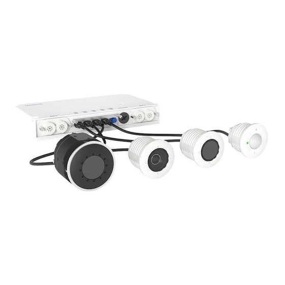
MOBOTIX S74: Scope of Delivery Fig. 1: Scope of delivery MOBOTIX S74 Scope of delivery MOBOTIX S74 Body Item Count Description MOBOTIX S74, complete Important Safety Information Sticker with IP address of camera Sticker with EAN number of camera Mounting supplies (see Mounting Supplies: Scope of Deliv- ery, p. -
Page 15: Mounting Supplies: Scope Of Delivery
Mounting Supplies: Scope of Delivery Fig. 2: Scope of Delivery MOBOTIX S74 Mounting Supplies Scope of Delivery MOBOTIX S74 Mounting Supplies Item Count Description Module wrench (gray) Lens wrench blue Tweezers Wood screw 4.5x60 mm Dowel S8 Washer... -
Page 16: Ptmount: Scope Of Delivery
PTMount: Scope of Delivery Fig. 3: Scope of delivery PTMount Scope of delivery PTMount Item Count Description PM.1 Sphere with rotating insert (installed) PM.2 Foot (installed) PM.3 Base plate (installed) PM.4 Swivel ring (installed) PM.5 Sealing PM.6 Washer Ø 4.3 mm, stainless steel PM.7 Wood screw 4x40 mm, stainless steel PM.8... -
Page 17: Ptmount-Thermal: Scope Of Delivery
PTMount-Thermal: Scope of Delivery Fig. 4: Scope of delivery PTMount-Thermal Scope of delivery PTMount-Thermal Item Count Description PM-T.1 Sphere with rotating Thermal/Thermal-TR sensor module (installed) PM-T.2 Foot (installed) PM-T.3 Base plate (installed) PM-T.4 Swivel ring (installed) PM-T.5 Sealing PM-T.6 Sensor cable 2 m/6.6 ft (installed) PM-T.7 Washer Ø... -
Page 18: Technical Specifications
Supported Image Sensor Modules Supported Thermal Sensor Modules Features Thermal Image Sensors Features ECO Thermal Image Sensor Functional Modules Interface Slide in Boards S74 Network Slide in Board with RJ45 socket S74 Network Slide in Board with LSA terminal 18 / 86... - Page 19 Technical Specifications S74 Network Slide in Board with RJ45 and VDC power supply Dimensions PTMount – Dimensions PTMount-Thermal – Dimensions 19 / 86...
-
Page 20: Hardware
Up to 30 m/100 ft (may be more depending on scene) mination Max. power consumption max. 25 W Electrical surge protection S74 Network Slide in Board with LSA terminal, p. 30 required PoE standard PoE Plus (802.3at-2009)/Class 4 (Network slide in Board required. See S74 Net- work Slide in Board with LSA terminal, p. -
Page 21: Image Formats, Frame Rates, Image Storage
1.130g ules Housing Aluminum, PBT-30GF Standard accessories MOBOTIX S74: Scope of Delivery, p. 14 Detailed technical doc- www.mobotix.com > Support > Download Center > Marketing & Docu- umentation mentation MTBF 80,000 hours Certificates EN 50121-4, EN 55032, EN 55035, EN 61000-6-1, EN 61000-6-2, EN 61000-6-3, EN 61000-6-4, EN 62368-1, EN 63000, AS/NZS CISPR32, 47 CFR Part 15b... -
Page 22: General Features
Playback and QuadView via web browser Animated logos on the image Master/Slave functionality Privacy zone scheduling Remote alarm notification (network message) Programming interface (HTTP-API) MOBOTIX MessageSystem ONVIF compatibility Profile G, S, T 22 / 86... -
Page 23: Video Analysis
Profile S, T MxAnalytics Heatmap, people counting & object-based counting MOBOTIX App support Video Management Software Feature Properties MOBOTIX HUB www.mobotix.com > Support > Download Center > Software Downloads MxManagementCenter Yes (MxMC 2.2 and higher) www.mobotix.com > Support > Download Center > Software Downloads 23 / 86... -
Page 24: Sensor Modules
Technical Specifications Sensor Modules Feature Properties MOBOTIX LIVE App Available in Android and iOS App Stores. Sensor Modules Dimensions of Sensor Modules Dimensions 58 x 42,5 (50 mm) (height x width) Weight of Sensor Modules Sensor Module Weight Standard Sensor Modules max. -
Page 25: Supported Image Sensor Modules
Sensor module with ultra wide angle lens 120° 4K Mx-O-M7SA-8DN040 Mx-O-M7SA-8D040 Mx-O-M7SA-8N040 Mx-O-M7SA-4DN040 For a complete list of lenses for MOBOTIX cameras, please see the Lens Table document for MOBOTIX 7 mod- els on www.mobotix.com > Support > Download Center > Marketing & Documentation > Lens Table. -
Page 26: Supported Thermal Sensor Modules
Technical Specifications Sensor Modules Supported Thermal Sensor Modules Sensor module Order code CIF Thermal 45° x 35° MX-O-M7SB-336TS100 CIF Thermal 25° x 19° Mx-O-M7SB-336TS150 CIF Thermal 17° x 13° Mx-O-M7SB-336TS280 CIF Thermal Radiometry Mx-O-M7SB-336RS100 45° x 35° CIF Thermal Radiometry Mx-O-M7SB-336RS150 25°... -
Page 27: Features Thermal Image Sensors
Technical Specifications Sensor Modules can be configured simultaneously in so-called TR windows or over the complete sensor image over a tem- perature range of –40 to 550 °C/–40 to 1022 °F . The Thermal (non-TR) variants only measure in the center of the image (Thermal spot, 2x2 pixel). Features Thermal Image Sensors Feature Properties... -
Page 28: Features Eco Thermal Image Sensor
Technical Specifications Sensor Modules Feature Properties Power consumption CIF: 1W VGA: 1.2W IP rating IP67 IK rating IK04 Material PBT-30GF (housing); Germanium (lens) Software (included) Video management software MxManagementCenter Features ECO Thermal Image Sensor Feature Properties Thermal sensitivity Typ. 65 mK, IR range 7.8 to 14 µm Temperature measurement -40 to 330°C/ –40 to 626 °F range... -
Page 29: Functional Modules
Tele Lens Sensor Modules 15° and 30° Power consumption White Light Modules: 3,2 W at 100% brightness. Interface Slide in Boards S74 Network Slide in Board with RJ45 socket Order Code Mx-F-S7A-RJ45 Power Supply PoE Plus (802.3at-2009)/Class 4 Network RJ45 / Ethernet 1000Base-T... -
Page 30: S74 Network Slide In Board With Lsa Terminal
S74 Network Slide in Board with LSA terminal Order Code Mx-F-S7A-LSA Power Supply PoE Plus (802.3at-2009)/Class 4 Network LSA / Ethernet 1000Base-T S74 Network Slide in Board with RJ45 and VDC power supply Order Code Mx-F-S7A-RJ45-VDC Power Supply 12-24 V DC only - recommended 2,5-1,5A Network RJ45 / Ethernet 1000Base-T... -
Page 31: Dimensions
Technical Specifications Dimensions Dimensions NOTE! Download the drilling template from the MOBOTIX website: www.mobotix.com > Support > Down- load Center > Marketing & Documentation > Drilling Templates. CAUTION! Always print or copy the drilling template at 100% of the original size! Fig. 5: MOBOTIX S74: All measurements in mm PTMount –... -
Page 32: Ptmount-Thermal - Dimensions
Technical Specifications Dimensions Fig. 6: PTMount PTMount-Thermal – Dimensions NOTE! Download the drilling template from the MOBOTIX website: www.mobotix.com > Support > Down- load Center > Marketing & Documentation > Drilling Templates. CAUTION! Always print or copy the drilling template at 100% of the original size! - Page 33 Technical Specifications Dimensions Fig. 7: PTMount-Thermal 33 / 86...
-
Page 34: Mounting
Installing Sensor Module with PTMount Installing Sensor Module PTMount-Thermal Installing Slide In Boards Installing the S74 Network Slide in Board with RJ45 socket Installing the S74 Network Slide in Board with LSA terminal Installing the S74 Network Slide in Board with RJ45 and VDC power supply... -
Page 35: Before Mounting The Camera
WARNING! When laying cables indoors and outdoors, the current regulations for cable laying, lightning and fire protection must always be observed. MOBOTIX cameras and devices are protected against the effects of minor over voltages by a number of meas- ures. However, these measures cannot prevent larger surge voltages from causing damage to the camera. -
Page 36: Installing Sensor Modules
Measures should always be taken to protect this device from electrical surge damage. NOTE! Electrical surge protection is integrated in the S74 Network Slide in Board with LSA terminal (see Installing the S74 Network Slide in Board with LSA terminal, p. -
Page 37: Preparing The Sensor Modules
Mounting Installing Sensor Modules Preparing the Sensor Modules ① Remove the plastic nut from the sensor modules, remove ② the bayonet catch by rotating it counter-clockwise, then ③ remove the blue rubber plug Proceed by Installing the Sensor Modules ... - Page 38 Mounting Installing Sensor Modules 2. Connect the sensor module cable: Push the plug of each sensor module cable firmly into the connector at the back of the module until the connector is fully inserted into its seat until it doesn’t go in any further. CAUTION! The lug of the plug must point to the inside of the sensor module when plugged in.
-
Page 39: Installing Sensor Module With Ptmount
Mounting Installing Sensor Modules Installing Sensor Module with PTMount 1. Using the 2.5 mm Allen wrench, remove the two screws that hold the foot onto the swivel ring. 2. Remove swivel ring and base plate. 3. Make sure that there is enough space for installing the PTMount and that you can access it from the rear later on. - Page 40 Mounting Installing Sensor Modules 4. Drill the holes for the base plate using the drilling template and insert the screw anchors PTMount: Scope of Delivery, p. 5. In the center of the drilling template, drill another hole into the wall or faceplate for the sensor module cable. The hole should have a diameter between 15 and 35 mm.
- Page 41 Mounting Installing Sensor Modules 8. When tightening the screws, make sure that you can still rotate the swivel ring by hand. 9. Guide the sensor cable through the sealing, the swivel ring, the base plate and through the mounting surface to the cam- era.
- Page 42 Mounting Installing Sensor Modules 11. Use the two screws to affix the foot and sphere assembly to the swivel ring and make sure that the foot can still be rotated. 12. Loosen the two fastening screws of the insert ① , then rotate the insert so that the small bar opposite of the TOP/OBEN ②...
- Page 43 Mounting Installing Sensor Modules 15. Push the sensor module into the PTMount so that the MOBOTIX lettering is turned 90 degrees to the left vs. the TOP/OBEN lettering. 16. Using the module wrench (red or black), lock the sensor mod- ule by turning it 90 degrees to the right.
-
Page 44: Installing Sensor Module Ptmount-Thermal
Mounting Installing Sensor Modules 18. Adjust the sensor module temporarily by pointing it into the desired viewing direction. 19. Make sure that the TOP/OBEN label on the insert is pointing upwards. If this is not the case, loosen the two fastening screws using the 2.5 mm Allen wrench and rotate the insert. - Page 45 Mounting Installing Sensor Modules 2. Remove swivel ring and base plate. 3. Make sure that there is enough space for installing the PTMount-Thermal and that you can access it from the rear later on. The surface should be even and smooth so that the sealing lies flat on the surface.
- Page 46 Mounting Installing Sensor Modules 6. Hold the sealing, the swivel ring and the base plate as shown in the figure. 7. Attach the base plate using the supplied wood screws and washers. 8. When tightening the screws, make sure that you can still rotate the swivel ring by hand.
-
Page 47: Installing Slide In Boards
11. Adjust the sensor module temporarily by pointing it into the desired viewing direction. 12. Make sure that the MOBOTIX label on the insert is pointing upwards. If this is not the case, loosen the two fastening screws with the 2 mm Allen wrench and rotate the insert. -
Page 48: Installing The S74 Network Slide In Board With Rj45 Socket
The S74 Network Slide in Board with RJ45 socket is required to connect the camera to the network and to supply power via PoE. The S74 Network Slide in Board with RJ45 socket is not part of the scope of delivery (see Scope of Delivery, p. -
Page 49: Installing The S74 Network Slide In Board With Lsa Terminal
Installing the S74 Network Slide in Board with LSA terminal The S74 Network Slide in Board with LSA terminal is required to connect the camera to the network, to sup- ply power via PoE and to protect the camera from electrical surge. The S74 Network Slide in Board with LSA terminal is not part of the scope of delivery (see Scope of Delivery, p. - Page 50 Mounting Installing Slide In Boards Prepare S74 Network Slide in Board with LSA terminal and cable NOTE! You will need an LSA+/Krone tool for this procedure: Fig. 12: LSA+/Krone tool ① 1. Remove cover from slot 2 of the camera: Use a screwdriver to loosen both bolt screws and then pull out the plastic cover.
- Page 51 Installing Slide In Boards 4. Remove the insulation from the network cable as shown below: Attach the Network Cable to the S74 Network Slide in Board with LSA terminal 1. Insert the network cable into the Interface a board and make sure the rubber plug is properly seated all around the opening: Fig.
- Page 52 Fig. 17: Network wires connected using LSA+/Krone tool CAUTION! Remove all clipped wire ends to prevent short circuits. Attach the Grounding Cable to the S74 Network Slide in Board with LSA terminal WARNING! For surge protection it is strongly recommended to attach the ground wire! The maximum length of the grounding cable should be 1m to the ground potential (e.
- Page 53 Fig. 19: Ground wire connected to terminal Connect the S74 Network Slide in Board with LSA terminal with the cam- 1. Position the interface board on the guide rails in the slide-in slot and push it in with slight pressure until it ①...
-
Page 54: Installing The S74 Network Slide In Board With Rj45 And Vdc Power Supply
13) and must be ordered in addition to the camera. Fig. 21: S74 Network Slide in Board with RJ45 and VDC power supply CAUTION! The S74 Network Slide in Board with RJ45 and VDC power supply may only be installed in slot 2 of the camera! -
Page 55: Installing The S74 Io Slide In Board
Installing the S74 IO Slide in Board The S74 IO Slide in Board is designed for powering the camera from an external power source and connecting it to the network. The board is not part of the scope of delivery (see Scope of Delivery, p. - Page 56 Installing Slide In Boards Fig. 22: S74 IO Slide in Board CAUTION! The S74 IO Slide in Board may only be installed in slot 1 of the camera! CAUTION! Do not connect to the network at this stage! Since the camera must not run without sensor modules, the network connection will be established only after mounting the camera and connecting the sensor modules.
- Page 57 ① clicks into the socket. Then fix the board with the screw bolts Fig. 25: Connecting the S74 Network Slide in Board with RJ45 socket CAUTION! Do not connect to the network at this stage! Since the camera must not run without sensor modules, the network connection will be established only after mounting the camera and connecting the sensor modules.
- Page 58 Installing Slide In Boards Terminal Connectors All I/O connections to the camera can be made on the S74 IO Slide in Board which is not part of the part of scope of delivery of the camera. Allowed cable dimensions for cables connected to the PCB terminals...
- Page 59 Example: switching an LED light using the P7 outputs The outputs in the S74 O Interface board are using an optocoupler with an open collector. These outputs will require the use of an external DC power supply up to 50 volts with a pull-up resistor and support a maximum current of 10mA.
-
Page 60: Mounting The Camera
Resistor value = (12V – 2V) / 10mA = 1 k Connecting the Audio Cable Mx-A-S7A-AUCBL05-AN The cable is designed for connecting the MOBOTIX 7 Audio Module to the AudioIO of the S74 IO Slide in Board. The cable is not part of the scope of delivery (see Scope of Delivery, p. -
Page 61: Connecting Module Cables To The Camera
Plus (802.3at-2009) standard is available at the mounting position (see Connecting the Camera to the Net- work, p. 65). NOTE! Download the drilling template from the MOBOTIX website: www.mobotix.com > Support > Down- load Center > Marketing & Documentation > Drilling Templates. - Page 62 Mounting Connecting Module Cables to the Camera WARNING! When installing the sensor modules, make sure that the sensor module cables are not damaged or bent sharply! Up to 4 sensor modules can be connected to the camera. Additionally an USB-C interface is available Fig.
-
Page 63: Sensor Module Combinations
One thermal module can be used instead of one optical module Fig. 29: Module connectors of the MOBOTIX S74 You can use the following combinations of sensor modules, thermal, and functional modules on the MOBOTIX S74: 63 / 86... - Page 64 Mounting Connecting Module Cables to the Camera Module Connectors Module Comments Optical Sensor Modules Mx-O-M7SA-8DN050 4K IR Cut 90° Mx-O-M7SA-8D050 4K Day 90° Mx-O-M7SA-8N050 4K Night 90° Mx-O-M7SA-4DN050 ULL IR Cut 90° Thermal Sensor Modules Mx-O-M7SA-640R050 Thermal VGA Radiometry 90° Mx-O-M7SA-640T050 Thermal VGA 90°...
-
Page 65: Connecting The Camera To The Network
S74 IO Slide in Board instead Connecting the Camera to the Network Network and power supply of the camera are established via an S74 Network Slide in Board with RJ45 socket (see Installing the S74 Network Slide in Board with RJ45 socket, p. - Page 66 Connecting the Camera to the Network Fig. 30: Power supply using PoE switch according to PoE Plus (802.3at-2009) Connecting the S74 Network Slide in Board with RJ45 socket 1. Remove the white rubber plug from the RJ45 network connector. 2. Plug the network cable of the camera into the network connector.
- Page 68 Operating the Camera This section contains the following information: Getting Started LED states Boot Options of the Camera Network Settings Windows Linux / Unix Network Settings on the Camera in the Webbrowser Network Settings on the Camera in MxMC Focusing the TELE 15° Sensor Module 68 / 86...
-
Page 69: Operating The Camera Getting Started
1. Establish a connection to the camera and adjust the network settings if required: By factory default, MOBOTIX cameras are booting as DHCP client with an additional fixed IP address in the 10.x.x.x range (e.g., 10.16.0.128). Local computer networks usually have IP addresses in the 172 or 192 ranges. -
Page 70: Boot Options Of The Camera
Operating the Camera Boot Options of the Camera LED status Meaning green steady on normal operation green steady flashing technical error or misconfiguration Boot Options of the Camera By default, the camera starts as DHCP client and automatically tries to get an IP address from a DHCP server. To start the camera in a mode different from the default mode, you can activate the boot menu of the cam- era. - Page 71 Operating the Camera Boot Options of the Camera NOTE! The number of flashes corresponds to the current boot option. Switch the boot option: Briefly press the key (< 1 sec). After the last boot option, the camera returns to the first boot option (LED flashes once). LED flashes Boot Option Meaning...
-
Page 72: Network Settings
IP addresses. Network Settings Once the camera has been connected to the network, you need to set up the MOBOTIX camera's network interface accordingly. This step involves setting up and checking the network parameters of the camera. If your network has an active DHCP server or if it is already running on a 10.x.x.x network with a 255.0.0.0 net-... -
Page 73: Windows
Operating the Camera Network Settings Windows 1. Open the Windows Control Panel > Network and Internet > Network and Sharing Center > Change Adapter Settings > Ethernet. 2. Right-click on the relevant network adapter and select Properties. 3. Open the properties of Internet Protocol Version 4 (TCP/IPv4). 4. -
Page 74: Mac
3. The computer now has the additional IP address 10.16.0.11. Network Settings on the Camera in the Webbrowser 1. Use a web browser to access the web interface of the MOBOTIX camera and enter the factory IP address (e.g. 10.16.0.99). -
Page 75: Network Settings On The Camera In Mxmc
When starting MxManagementCenter for the first time, the configuration wizard opens and automatically starts searching for MOBOTIX cameras. The number of found cameras is shown as a counter next to the Add Devices icon . This number is updated automatically if the number of MOBOTIX cameras on the network has changed (i.e., by connecting new/disconnecting existing cameras). - Page 76 NOTE! Using the Bonjour service (en.wikipedia.org/wiki/Bonjour_(software)), the application finds not only MOBOTIX cameras on the same subnet, but also in other subnets. Normally, you would not be able to estab- lish any connection to cameras in a different network or subnet.
-
Page 77: Focusing The Tele 15° Sensor Module
To correct image sharpness, you can also make use of the visual focusing aid of the camera (see the Camera Reference Manual, section The Live View of the MOBOTIX Camera) 1. Show the live image of the camera on your monitor. - Page 78 Operating the Camera Focusing the TELE 15° Sensor Module 5. Insert the gray module wrench (with its two small pins) into the holes of the lens and cautiously turn to the left and to the right. Adjust the image sharpness according to the live image on the computer monitor: CAUTION! Never apply force when turning the lens and never screw the lens too deep into the thread since this could damage the image sensor! If in doubt, keep turning the lens counter-clockwise, then turn clockwise to focus the lens.
- Page 79 Operating the Camera Focusing the TELE 15° Sensor Module 8. Using the lens wrench, press the lens protection glass firmly into the sensor module, until the glass fits flush with the sensor module housing. 9. Turn the lens protection glass clockwise using the blue lens wrench until it locks in place. 10.
-
Page 80: Camera Software In The Browser
Camera Software in the Browser The integrated software of the MOBOTIX S74 features a multitude of functions, such as video motion detection, long-term recording, alarm messaging and video IP telephony. Especially remarkable are the AI-based analytics features and the possibility to install third- party apps on the camera. -
Page 81: Access The Camera's Website In The Browser
Access the camera's website in the browser Access the camera's website in the browser Once the power and network connection of the MOBOTIX have been established, you can open the interface of the camera software in a web browser. Fig. 32: The interface of the camera software 1. -
Page 82: Configuring Sensor Modules
Using different combinations of sensor modules of the MOBOTIX S74 will have an influence on the display modes and configuration variants that are available. An MOBOTIX S74 will automatically check and verify the installed sensor modules upon its first start and at every reboot thereafter (e.g., focal length, Day or Night variant). Please note the following: ... - Page 83 (and vice versa), without having to physically swap the module connectors at the camera itself. Exchanging sensor modules: In this case, the MOBOTIX S74 will display a message box and will log a system message to inform you that sensor modules have been exchanged .
-
Page 84: Maintenance
Maintenance Maintenance This section contains the following information: Cleaning the Camera and Lenses 84 / 86... -
Page 85: Cleaning The Camera And Lenses
Maintenance Cleaning the Camera and Lenses Cleaning the Camera and Lenses Clean the camera housing using a mild alcohol-free detergent without abrasive particles. To protect the lens protection glass, only use the supplied mounting supplies (see Mounting Supplies: Scope of Delivery, p. Cleaning the lens protection glass ... - Page 86 MOBOTIX AG • Kaiserstrasse • D-67722 Langmeil • Tel.: +49 6302 9816-103 • sales@mobotix.com • www.mobotix.com MOBOTIX is a trademark of MOBOTIX AG registered in the European Union, the U.S.A., and in other countries. Subject to change without notice. MOBOTIX do not assume any liability for technical or editorial errors or omissions contained herein. All rights reserved. © MOBOTIX...
Need help?
Do you have a question about the S74 and is the answer not in the manual?
Questions and answers