Advertisement
Quick Links
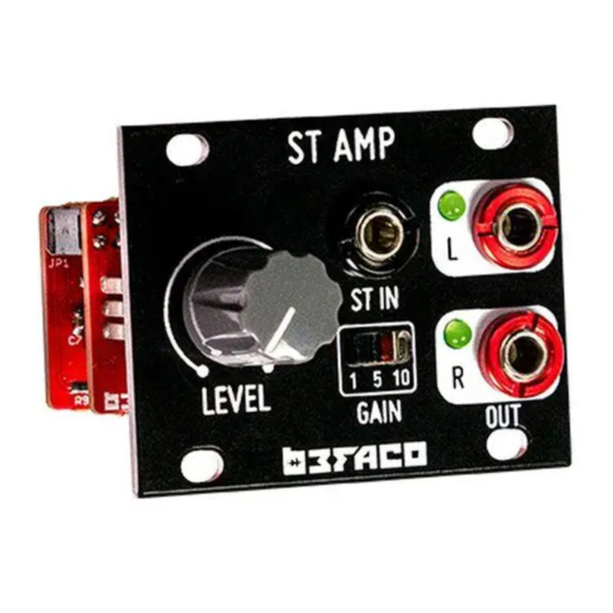
STAmp 1U - ASSEMBLY GUIDE – Rev. Mar 2023
THANKS FOR CHOOSING ONE OF OUR KITS!
This assembly guide has been designed taking into account the common issues that we often find people experience in
our workshops. The order in which the components are placed on the board is meant to make assembly as easy as
possible.
Some steps are not obvious, so even if you're an experienced DIYer, please take the time to read the steps thoroughly
before starting.
If this is your first project, please read this article before you start assembling the kit:
www.befaco.org/howto/
GOOD LUCK!
PIN HEADERS
Place and solder the Pin Headers on the silkscreen side of the main board (It is the shorter pins that you are soldering).
Double check they all are perfectly straight.
Qty
PINs
1
2x6
SOCKET CONNECTORS
Place the socket connectors on the control board over the silkscreen markings at positions and solder. Double check they
all are perfectly straight.
Qty
PINs
1
2x6
IDC CONNECTORs
Solder the IDC connectors at bottom face of main board. Orientation is marked by the notch on silskreen, also the small
arrow on the connectors must be on the side with the thick white line or a arrow.
Qty PINs
1
2x3
1
2x5
3 POSITION SWITCH
Place the switches on their right places, push them till are flush to the PCB.
Double check they all are perfectly straight and solder them.
Qty
Type
1
Mini. 2 circuits 3 position
Name on PCB
JP1
Name on PCB
JP2
Name on PCB
INPUT
POWER
Name on PCB
SW100
1
Advertisement

Related Manuals for Befaco STAmp 1U


Summary of Contents for Befaco STAmp 1U
- Page 1 STAmp 1U - ASSEMBLY GUIDE – Rev. Mar 2023 THANKS FOR CHOOSING ONE OF OUR KITS! This assembly guide has been designed taking into account the common issues that we often find people experience in our workshops. The order in which the components are placed on the board is meant to make assembly as easy as possible.
- Page 2 STAmp 1U - ASSEMBLY GUIDE – Rev. Mar 2023 FRONT PANEL COMPONENTS MOUNTING TIPS: Now we will proceed to mount the jacks, LEDs and potentiometers. This part of the assembly is CRITICAL. Please take your time and read the instructions carefully.
- Page 3 STAmp 1U - ASSEMBLY GUIDE – Rev. Mar 2023 FRONT PANEL Attach the front panel adjusting the parts one by one if necessary until they fit. At this point a pair of fine tweezers can be helpful. To finish: - Secure the parts to the panel in this order: A) Mini-jacks B) Pot - Ensuring all of the above parts are flush with the panel then you can finally solder them!