
Related Manuals for OZGENC MAKINA SL 500


Summary of Contents for OZGENC MAKINA SL 500
- Page 1 AUTOMATIC ALUMINUM PROFILE SLICING MACHINE OPERATING MANUAL www.ozgencmachine.com...
-
Page 3: Table Of Contents
CONTENTS 1. INTRODUCTION .................... 3 2. INTENDED USE ....................4 3. TECHNICAL SPECIFICATIONS ................5 3.1 Table of Technical Specifications ........................6 3.2 General Dimensions ............................7 3.3 Cutting Diagram ..............................7 3.4 Product Information Card ..........................8 4. MACHINE STRUCTURE AND LAYOUT ............. 9 4.1 General Structure ............................ - Page 4 CONTENTS 7. USE OF MACHINE ..................22 7.1 Turning On the Machine ..........................23 7.2 Manual Operation Mode ..........................25 7.3 Automatic Operation Mode ..........................26 7.4 Settings Page ..............................27 7.5 Alarms Page ..............................27 7.6 Inlets & Outlets Page ............................28 7.7 Saw Outlet Speed Adjustment .........................
-
Page 5: Introduction
INTRODUCTION Özgenç Makina, which manufactures PVC and aluminum processing machines, has stood out among the leading companies of the industry with the importance it attaches to quality since its establishment. Integrating ISO 9001:2000 Quality Management System in its plant with a space of 5.000 m² in total, the indoor area of which is 4.500 m², Özgenç... -
Page 6: Intended Use
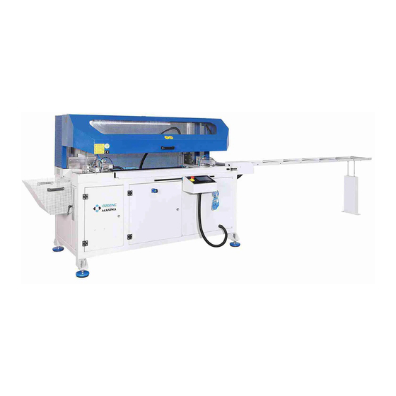
INTENDED USE SL 500 machine is designed for cutting the aluminum wedge profiles. It is wrong and forbidden to use for the wrong purposes. Our company cannot be held responsible for misuse. General Features; • PLC control system • Having two heads, with one being fixed and other one being mobile •... -
Page 7: Technical Specifications
TECHNICAL SPECIFICATIONS 3.1 Table of Technical Specifications ........................6 3.2 General Dimensions ............................7 3.3 Cutting Diagram ..............................7 3.4 Product Information Card ..........................8... -
Page 8: Table Of Technical Specifications
TECHNICAL SPECIFICATIONS 3.1 Table of Technical Specifications Operating Voltage Current 13,5 Used Force Operating Pressure Total Air Consumption L/cycle Saw Motor Operating Voltage Engine Power Engine Speed 3000 Servo Motor Operating Voltage Volt (V) Engine Power Watt (W) Engine Speed 3000 Profile Sliding Distance 1280... -
Page 9: General Dimensions
TECHNICAL SPECIFICATIONS 3.2 General Dimensions 1100 mm 5275 mm 345 mm 3000 mm Length (L) Width (W) Height (H) 5275 mm 1100 mm 1550 mm 3.3 Cutting Diagram Ø500 mm 90° Ø 165 mm... -
Page 10: Product Information Card
M.S.K MOTOR KOMPRESÖR MAK. SAN. TİC. LTD. ŞTİ. ÜRETİCİ / PRODUCER Otomatik Alüminyum Profil Dilimleme Makinası KOD / ADI / CODE / NAME SL 500 Automatic Aluminium Profile Slicing Machine 22SLM500001 SERİ NO / SERIAL NO ÜRETİM TARİHİ / PROD. DATE 2022 GÜÇ... -
Page 11: Machine Structure And Layout
MACHINE STRUCTURE AND LAYOUT 4.1 General Structure ............................10 4.2 Machine Layout ............................... 11... -
Page 12: General Structure
MACHINE STRUCTURE AND LAYOUT 4.1 General Structure A Protection cover F Servo motor case B Wedge collection reservoir G Profile conveyor C Saw cabinet H Dust outlet (Ø100 mm) D Control panel I Air circulation E Electrical panel J Pneumatic panel... -
Page 13: Machine Layout
MACHINE STRUCTURE AND LAYOUT 4.2 Machine Layout For machine layout, pay attention to the movement area required for operation of the machine, and of the appropriate distance to enable the panel doors to open when necessary. Take following measures into account for safe operation. -
Page 14: Occupational Safety And Measures
OCCUPATIONAL SAFETY AND MEASURES 5.1 Safety and Accident Measures ........................13 5.2 Machine Usage and Misuse ..........................13 5.3 General Safety Rules ............................13 5.4 Maintenance Measures for Safety ........................13 5.5 Electrical Safety Rules .............................13 5.6 Lighting ................................13 5.7 Connections ..............................13 5.8 Earthing Requirements ...........................13 5.9 Noise Emission .............................. -
Page 15: Safety And Accident Measures
5.3 General Safety Rules Only one operator must work on SL 500 machine. Operator must not operate the machine in case of any lack of attention caused by drugs, alcohol or medication. Operator must check the machine and components prior to operation. -
Page 16: Noise Emission
OCCUPATIONAL SAFETY AND MEASURES 5.9 Noise Emission There is no noise emitted by machine units, which will impact the health of employee. 5.10 Disposal of Hazardous Substances In case the user uses equipment such as lubrication, cooling, etc., then apply the methods indicated on respective labels. -
Page 17: Risk Areas And Warning Tags
OCCUPATIONAL SAFETY AND MEASURES 5.12 Risk Areas and Warning Tags Despite of the safety measures taken on the machine through equipment, it is also required to comply with additional visual safety measures at the operating site. Warning symbols and phrases in this document should be taken into consideration. - Page 18 OCCUPATIONAL SAFETY AND MEASURES • The machine has been checked for its functionality within our company. ISO VİSKOZİTE 10 • The oil types stated on the side tag are used in the conditioner unit of the DODGE Deolube 10-S machine. MOBIL Velocite 6 SHELL TELLUS Tellus (Spindle) 10 •...
-
Page 19: Commissioning And Installation
COMMISSIONING AND INSTALLATION 6.1 Domestic Transportation ..........................18 6.2 Overseas Transportation ..........................18 6.3 Fault Control During Shipment ........................18 6.4 Placement of Machine ............................19 6.5 Fixing on Ground .............................19 6.6 Preparation for Commissioning ........................19 6.7 Electrical Connections .............................19 6.8 Electrical Panel ..............................20 6.9 Pneumatic Connections .......................... -
Page 20: Domestic Transportation
COMMISSIONING 6.1 Domestic Transportation Our machines are specially packed in accordance with their sizes and weight criteria. Main purpose of packaging is to safely deliver the product free-of-damage to our customer. Some parts may be shipped as disassembled in line with the agreements with customer. Prior to transportation, all detailed criteria are set through a contract signed between parties. -
Page 21: Placement Of Machine
MACHINE INSTALLATION Take necessary precautions while the machine is being taken off the vehicle. Prevent the slippage of the machine. While picking the machine, lifting procedure must be carried out without damaging its body. The machine legs that are taken off before transportation must be mounted again. Expert M.S.K. -
Page 22: Electrical Panel
MACHINE INSTALLATION 6.8 Electrical Panel This electrical panel scheme is presented solely for the purpose of placement of components within the panel. Please see ANNEXES for a detailed electrical diagram. AC Currency Filter Soft Starter Contactor Phase Protection Relay Fuse Driver Main Switch 24V 5A Power Supply... -
Page 23: Pneumatic Connections
MACHINE INSTALLATION 6.9 Pneumatic Connections Required air pressure for the machine to properly function is 6 bars. Check the manometer. Attach the air hose from the compressor to this inlet. Make sure that your air supply is dry! Solenoid Valve group controls the motion of current pneumatic equipment. -
Page 24: Use Of Machine
USE OF MACHINE 7.1 Turning On the Machine ..........................23 7.2 Manual Operation Mode ..........................25 7.3 Automatic Operation Mode ..........................26 7.4 Settings Page ..............................27 7.5 Alarms Page ..............................27 7.6 Inlets & Outlets Page ............................28 7.7 Saw Outlet Speed Adjustment ......................... 28 7.8 Replacing Saw ..............................29 7.9 Procedure of Turning Off/On the Compression Pistons and Adjusting Their Speeds Manually ..... -
Page 25: Turning On The Machine
USE OF MACHINE 7.1 Turning On the Machine Check whether there are any foreign objects on machine prior to operation. Rotate the main switch clockwise until it slots into place. (Main switch disconnects the power from the main line completely.) Rotate the main switch clockwise until it slots into place. - Page 26 USE OF MACHINE Check the emergency stop button, it should be at the back! If the machine is turned on while the emergency stop button is pushed, the main screen indicates the emergency stop button. Once the emergency stop button is released, this screen disappears and the main screen appears. If the main screen does not appear, it means that there are other alarms that need to be reset.
-
Page 27: Manual Operation Mode
USE OF MACHINE 7.2 Manual Operation Mode “M” button on the main screen is pressed to work in manual mode, and then the following screen appears. When the machine is on manual operation mode, the part is cut by being held in any position or according to the size entered digitally. -
Page 28: Automatic Operation Mode
USE OF MACHINE 7.3 Automatic Operation Mode “Auto” is selected on the main screen to work in automatic mode, and then the following screen appears. When the machine is in the operating mode, the cutting is performed according to the sizes written on the length column on the automatic cutting screen. -
Page 29: Settings Page
USE OF MACHINE 7.4 Settings Page The machine will ask password to open “Setting” page through which the language selection and below- mentioned settings are made. You can access this screen via the password you obtain from the company. You can set the date and time by pressing the “Screen”-marked button on the Settings screen. -
Page 30: Inlets & Outlets Page
USE OF MACHINE 7.6 Inlets & Outlets Page The faults in the machine are displayed on this page. The authorized service may request information on this page from you in case of a fault in the machine. 7.7 Saw Outlet Speed Adjustment You can slow down or speed up the saw outlet by turning the screw in the figure. -
Page 31: Replacing Saw
USE OF MACHINE 7.8 Replacing Saw Wrench Pneumatic Piston Flange Electric Motor Hydropneumatic Piston Take measures against cuts while carrying out saw maintenance and replacement procedures. Make sure the switch is turned off. Operation must be performed by expert technical personnel. 1. -
Page 32: Procedure Of Turning Off/On The Compression Pistons And Adjusting Their Speeds Manually
USE OF MACHINE 7.9 Procedure of Turning Off/On the Compression Pistons and Adjusting Their Speeds Manually Compression/Fixing Piston 1 On - Off Valve Piston Speed Regulation Valves Compression/Fixing Piston 1 There are two small valves next to the pneumatic hose inlets of the compression/fixing pistons. These valves are used to turn off or on the pistons or to adjust their speeds in forward and backward direction. -
Page 33: Procedure Of Increasing Or Decreasing The Compression Force Of Upper Fixing/Compression Pistons
USE OF MACHINE 7.11 Procedure of Increasing or Decreasing the Compression Force of Upper Fixing/Compression Pistons Upper Fixing Pistons Pneumatic Pressure Adjuster Pneumatic compression adjuster at the back of pistons is used to increase or decrease the compression force of upper fixing/compression pistons. •... -
Page 34: Maintenance
MAINTENANCE 8.1 General Maintenance ............................33 8.2 Conditioner Water Level Control ........................33 8.3 Conditioner Oil Level Control ..........................33 8.4 Cylinder Settings .............................33 8.5 Maintenance of Filters ............................34 8.6 Cylinder Sensor Settings ..........................34 8.7 Cooler Settings ..............................35 8.8 Belt Setting ..............................36 8.9 Lubrication Process ............................ -
Page 35: General Maintenance
MAINTENANCE 8.1 General Maintenance Before performing any maintenance on the machine, make sure that the electrical and pneumatic supply is cut off. Certain parts of the machine can be hazardous when electrical equipment is energized. The operator must not stay close to the machine during maintenance operations. All maintenance operations must be carried out by qualified personnel in accordance with all safety precautions. -
Page 36: Maintenance Of Filters
MAINTENANCE 8.5 Maintenance of Filters Pressure adjustment: Pull up the regulator cap indicated with "1". Rotating clockwise will increase the outlet air pressure of the conditioner, while rotating counter-clockwise will decrease the pressure. The pressure value must be within the range specified in the technical specifications. Discharging the condensation fluid: Press the small pin in the place indicated with “2”... -
Page 37: Cooler Settings
MAINTENANCE 8.7 Cooler Settings Coolant flow rate should be adjusted according to the cutting operation you perform on your machine as well as to the type and dimensions of the piece that is cut. You can adjust the coolant flow rate by turning the coolant valve shown in the figure. -
Page 38: Belt Setting
MAINTENANCE 8.8 Belt Setting Take necessary occupational safety measures before replacing the belt. The main switch and the air inlet of the machine must be DEFINITELY closed! Belts running as connected to the motor in machines may loosen or be deformed over time. For this reason, the tension of the belts should be checked every six months and adjusted to the appropriate tension setting if necessary. -
Page 39: Lubrication Process
8.9 Lubrication Process Lubricators are shown on the SL 500 machine below. Lubricators are on the linear guides and shafts as shown in the figure. The oil status of these parts should be checked manually and visually on a weekly basis and appropriate oil should be added with a pump when necessary. -
Page 40: Table Of Periodic Maintenance
MAINTENANCE 8.10 Table of Periodic Maintenance Semi Maintenance Items Daily Weekly Monthly Quarterly Annually Annually Cleaning of oil and waste on and around the machine Cleaning of slides, screw shafts, moving parts and sensing surface of sensors and proximity switches, if any Conditioner water level check (8.2 - 8.5) ... -
Page 41: Problems And Solutions
PROBLEMS AND SOLUTIONS 9.1 Problems and Solutions ...........................40 9.2 Warnings and Solutions ..........................41 9.3 Alarms and Solutions............................41... -
Page 42: Problems And Solutions
PROBLEMS AND SOLUTIONS 9.1 Problems and Solutions Fault Possible Reason Solution • Main board switch is turned Machine fails to draw power • Turn on main switch Pneumatic equipment do • Machine fails to draw air • Check the compressor line not operate and/or pistons •... -
Page 43: Warnings And Solutions
PROBLEMS AND SOLUTIONS 9.2 Warnings and Solutions Warning Solution ‘Reset servo’ alarm Press ‘reset’ seen on the screen ‘Piece height not entered’ Enter the piece height by opening prescription page from program writing alarm menu ‘Cutting time not entered’ Enter the cutting time present on the Manual operation or Automatic alarm operation mode screen It indicates that the material is run out before the cutting profiles... -
Page 44: Warranty Disclaimer
WARRANTY DISCLAIMER... - Page 45 WARRANTY DISCLAIMER Warranty period starts as of the invoice date and it is 2 (two) years for domestic sales and 1 (one) year for overseas sales. The machine is under our company's warranty for any manufacturing and material-related defects. If the machine breaks down within the term of warranty, the period of time spent to repair is added to the term of warranty.
- Page 46 OUT-OF-WARRANTY CASES Consumables (milling, drilling bits, saws, teflon, etc.) are out of warranty. After the machine(s) is/are embarked by the Vendor, the Buyer shall be responsible for any damage and malfunction that occur during unloading or handling. The faults that occur because original part is not used are out of warranty. The faults that occur due to carelessness and ignorance of the user are out of warranty.
-
Page 47: Appendices
APPENDICES 1-) ELECTRICAL CIRCUIT DIAGRAM ........................46 2-) PNEUMATIC CIRCUIT DIAGRAM ........................56 3-) MATERIAL LIST ...............................57 4-) DECLARATION OF CONFORMITY .........................59... -
Page 48: Electrical Circuit Diagram
1-) ELECTRICAL CIRCUIT DIAGRAM... - Page 50 2/T1 1/L1 4/T2 3/L2 6/T3 5/L3 05-8 11-7...
- Page 51 24VDC 06-2 24VDC 06-3 24VDC 08-1 24VDC 24VDC 24VDC 24VDC 24VDC 24VDC 24VDC 24VDC 24VDC 24VDC 24VDC 24VDC 0VDC 06-2 0VDC 04-10 0VDC 06-3 0VDC 08-1 0VDC 0VDC 0VDC 0VDC 0VDC 0VDC 0VDC...
- Page 52 05-4 05-8...
- Page 57 04-10...
-
Page 58: Pneumatic Circuit Diagram
2-) PNEUMATIC CIRCUIT DIAGRAM... -
Page 59: Material List
3-) MATERIAL LIST No Name Quan�ty D-M9P Piston Posi�on Sensor (Open) Ø32 x 200 Cylinder Regulator Gas Spring (DESPA--350N) Pin Limit Switch M12 Induc�ve Proximity Switch M18 Op�cal Proximity Switch Ø32 x 150 Cylinder 750 W 3000 rpm Servo Motor... - Page 60 No Name Quan�ty Coolant Nozzle 4 kW 2875 rpm Electric Motor Ø 500 Saw D-M9P Piston Posi�on Sensor (Open) Ø 50 x 200 Pneuma�c Cylinder Ø 40 x 220 Hydropneuma�c Cylinder Belt (8PK980) Roller Limit Switch...
-
Page 61: Declaration Of Conformity
4-) DECLARATION OF CONFORMITY... - Page 62 NOTES...
- Page 63 NOTES...
- Page 64 M.S.K Motor Kompresör Mak. San. Tic. Ltd. Şti. Address: Nilüfer Organized Industrial Zone 113. Sk. No: 23 Nilüfer Bursa Turkey 16250 Telephone: +90 224 411 07 46 Fax: +90 224 411 07 49 E-mail: info@ozgencmakina.com.tr Web: www.ozgencmachine.com Thank you for choosing us...
Need help?
Do you have a question about the SL 500 and is the answer not in the manual?
Questions and answers