
Related Manuals for OZGENC MAKINA SL 500


Summary of Contents for OZGENC MAKINA SL 500
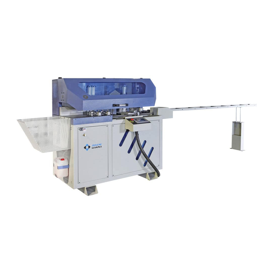
- Page 1 OPERATOR'S MANUAL OPERATOR'S MANUAL AUTOMATIC ALUMINUM BLOCK CUTTING MACHINE AUTOMATIC ALUMINUM BLOCK CUTTING MACHINE AUTOMATIC ALUMINUM BLOCK CUTTING MACHINE www.ozgencmakina.com.tr...
-
Page 2: Table Of Contents
SL 500 USER MANUAL CONTENTS GENERAL INFORMATION ................................4 1. DOCUMENT PUBLICATION INFORMATION ........................4 1.1 After Sales Service ..................................4 1.2 The Procedures to Be Followed ............................6 2. SCOPE OF THE USER MANUAL ..............................7 3. Machine Description ..................................7 Options: ........................................ - Page 3 SL 500 USER MANUAL 9.4 Control Panel and Specifications ..........................32 9.5 Moving Equipment Over Machine ..........................33 9.6 SL 500 Aluminum Block Cutting and Machine Settings ...................35 9.7 Process of Manually Setting Saw Output Speed ....................46 9.8 Process of Replacing Engine Belt ..........................47 9.9 Process of Replacing Saw ...............................49...
-
Page 4: General Information
SL 500 USER MANUAL GENERAL INFORMATION This part contains general topics about the user manual. 1. DOCUMENT PUBLICATION INFORMATION REVISION 2016 1.1 After Sales Service Address: Nilüfer Organize Sanayi Bölgesi 113. Sk. No:23 Nilüfer BURSA/TURKEY 16250 Contact: PHONE: +90 224 411 07 46 FAX: +90 224 411 07 49 E-mail: info@ozgencmakina.com.tr... - Page 5 SL 500 USER MANUAL 1.2 Documentation Process The machine (OMRM 125) whose technical characteristics are described in user manual complies with CE norms. Safety measures were taken in accordance with CE norms. We can provide CE documents upon request. P a g e...
-
Page 6: The Procedures To Be Followed
SL 500 USER MANUAL M.S.K MOTOR KOMP. MAKİNA SAN. TİC. LTD. ŞTİ. ÜRETİCİ / PRODUCER Otomatik Alüminyum Takoz Kesim Makinası SL 500 KOD / ADI / CODE / NAME Aluminium Corner Connector Profile Cutting Machine 2015 10D50342 SERİ NO / SERIAL NO ÜRETİM TARİHİ... -
Page 7: Scope Of The User Manual
• +/- 0.1 mm cutting precision • Cutting list creation capability • Protection cover system with safety key • Touchscreen • 500 mm diamond tip circle saw Options: There is no option for SL 500 Aluminum block cutting machine. P a g e... -
Page 8: Machine Cutting Capacity
SL 500 USER MANUAL 3.1 Machine Cutting Capacity +/- 0.1 mm cutting precision 500mm diamond tip saw Automatic slicing capability P a g e... -
Page 9: Machine Specifications
SL 500 USER MANUAL 3.2 Machine Specifications 3.2 Machine Specifications Operating Voltage Volt (V) Total Drawn Power Kilowatt (Kw) Drawn Current Amper (A) Operating Pressure Total Air Consumption Amount Lt/Min Saw Engine Saw Engine Power Kilowatt (Kw) Engine Revolution 2810... -
Page 10: Machine Layout And Unit Structure
SL 500 USER MANUAL 4. Machine Layout and Unit Structure A- Protective Cover B- Block Collection Reservoir C- Servo Engine Protective Cover D- Saw Cabinet E- Electrical Board Cabinet F- User Control Panel 10 | P a g e... - Page 11 SL 500 USER MANUAL A- Upper Profile Thrust/Fixation Pistons B- Side Profile Thrust/Fixation Pistons C- Profile Quantity Determination Sensor D- Cover Security Switch E- Dual Slide Group 11 | P a g e...
- Page 12 SL 500 USER MANUAL A- Pneumatic Adjustment Panel B- Shaving Discharge Reservoir C- Air Circulation Hole 12 | P a g e...
- Page 13 SL 500 USER MANUAL Structure of Conveyor A- Conveyor Feet B- Machine Connection Plate 13 | P a g e...
-
Page 14: General Measurements Of The Machine
SL 500 USER MANUAL 4.1 General Measurements of the Machine 14 | P a g e... -
Page 15: Machine Layout
SL 500 USER MANUAL 4.2 Machine Layout During machine layout, consider the freedom of movement required for profile cutting operation. Also, consider appropriate distances for opening machine panel covers. Consider the following measurements in order to work safely. 15 |... -
Page 16: Work Safety And Precautions
5.3 Machine Usage and Wrong Uses SL 500 Aluminum block cutting machine is only produced for profile cutting operation. The user is responsible for the machine breakdowns and work safety gaps arising from machining during cutting operations excluding profile cutting. -
Page 17: General Safety Rules
SL 500 USER MANUAL 5.4 General Safety Rules It is appropriate for SL 500 Aluminum block cutting machine to be used by one operator. If the operator has attention deficit because of drugs, alcohol and medicine, he should never work. -
Page 18: Wiring
SL 500 USER MANUAL 5.8 Wiring All of the necessary wiring should be set properly in accordance with the machine. The needs such as electric energy, pneumatic needs, etc. should have proper values and the compatible equipment should be placed in the layout area. IEC 64-8 norm should be taken into consideration while installing the electrical equipment. -
Page 19: Safety Equipment
SL 500 USER MANUAL 6. Safety Equipment DANGER! It is absolutely forbidden to eliminate the measures taken for the machine and the devices and deactivate them. Main Switch Cover Security Switch 19 | P a g e... - Page 20 SL 500 USER MANUAL Emergency/Stop Button 20 | P a g e...
-
Page 21: Risk Areas And Warnings
SL 500 USER MANUAL 6.1 Risk Areas and Warnings 6.1 Risk Areas and Warnings In addition to the safety measures taken for the In addition to the safety measures taken for the machine with the equipment, extra visual machine with the equipment, extra visual safety measures in the working site should be followed. -
Page 22: Noise Propagation
SL 500 USER MANUAL 6.2 Noise Propagation Machine units do not propagate noise which may affect the workers adversely. 6.3 Disposal of Harmful Substances If the substances such as grease, cooling agents, etc. are used, apply the procedures written on their labels. - Page 23 SL 500 USER MANUAL A- Forklift B- Machine C- Transportation Vehicle Take necessary precautions when machine is taking over the vehicle. Anti-slip precautions are taken. Raising operation should be done without damaging the body during lowering the machine . Machine feet, which is removed during transportation, should be reinstalled.
-
Page 24: Overseas Transportation
SL 500 USER MANUAL 7.2 Overseas Transportation Our machines which are sent overseas, are packed with wooden boxes proportional to machine dimensions. Some peripheral equipment which can be damages during packaging are removed and packaged separately. 7.3 Breakdown Check for the Transportation The machine should be checked against any breakdown and damage that may occur during the transportation. -
Page 25: Start-Up Preparation
SL 500 USER MANUAL 8.3 Start-up Preparation The moving parts of the machine are generally cleaned with special rust preventive oils. Electrical and pneumatic connections are made to ensure the complete functioning of the machine. 8.4 Electrical Connections 400 V... -
Page 26: Electrical Panel Diagram And Equipment Structure
SL 500 USER MANUAL 8.5 Electrical Panel Diagram and Equipment Structure This electrical panel diagram is only given for the layout of elements within panel. For detailed electrical diagram, see APPENDIX chapter. A- Connector Group B- Servo Driver C- Power Supply... -
Page 27: Sensors Used In Machine And Their Duties
SL 500 USER MANUAL 8.6 Sensors Used in Machine and Their Duties Forward limit sensor Determines max. point that slide can come Material yes-no sensor Determines whether the cut profile is finished 27 | P a g e... - Page 28 SL 500 USER MANUAL Back limit sensor Determines min. point that slide can come Reset sensor 28 | P a g e...
-
Page 29: Pneumatic Connections
SL 500 USER MANUAL 8.7 Pneumatic Connections For healthy machine operation, 6 bar air is necessary. Check manometer indicator. Connect main air hose from compressor into this input. Caution: Pay attention that the air supply should be dry! Solenoid valve group controls the movement of the present pneumatic equipment. When needed, manual movements can be via the valve. -
Page 30: Machine Use
SL 500 USER MANUAL 9. Machine Use 9.1 Machine Start/Stop Before operating the machine, check if there is any foreign object on the machine. 9.2 Opening the Machine Turn the main switch clockwise until it fits. Check if EMERGENCY/STOP button on the manual control panel is at the back. -
Page 31: Control List
SL 500 USER MANUAL (EMERGENCY STOP BUTTON SHOULD BE AT THE BACK.!!) 9.3 Control List Main switch: Main switch cuts of the electricity from the main line. Emergency stop on operator panel only stops operation. Contact with moving parts can cause electric shock. -
Page 32: Control Panel And Specifications
SL 500 USER MANUAL 9.4 Control Panel and Specifications A- EMERGENCY/STOP Button B- Touchscreen Operator User Panel 32 | P a g e... -
Page 33: Moving Equipment Over Machine
SL 500 USER MANUAL 9.5 Moving Equipment Over Machine A- Upper Profile Thrust/Fixation Pistons B- Side Profile Thrust/Fixation Pistons C- User with Slide Control Panel D- Mobile Double Slide Group 33 | P a g e... - Page 34 SL 500 USER MANUAL A- Saw B- Hydro-Pneumatic Piston C- Pneumatic Piston 34 | P a g e...
-
Page 35: 500 Aluminum Block Cutting And Machine Settings
SL 500 USER MANUAL 9.6 SL 500 Aluminum Block Cutting and Machine Settings Machine Usage Steps -Screen Menu A. It is used for single part cutting by entering a single measurement B. Recipe that is prepared for program coding is in process and it is used for automatic cutting C. - Page 36 SL 500 USER MANUAL -Use of Manual Operation Mode For manual operation mode, operator clicks on Main Menu > Manual operation mode in touchscreen control panel 36 | P a g e...
- Page 37 SL 500 USER MANUAL 1- Piston on the left side of saw, that holds profile to be cut. 2- Piston on the right side of saw, that holds profile to be cut. 3- Piston which fixes profile in forward 4- Sends driving mechanism to zero position...
- Page 38 SL 500 USER MANUAL A- Thrust Piston 1 B- Thrust Piston 2 C- Thrust Piston 3 Sends driving mechanism to zero position 38 | P a g e...
- Page 39 SL 500 USER MANUAL Used to enter numeric values that will be used in profile cutting operation After the required settings are entered by operator, profiles to be cut are loaded and then “START” button on user panel is pressed.
- Page 40 SL 500 USER MANUAL After the required settings are entered and profile is loaded, START button is pressed 40 | P a g e...
- Page 41 SL 500 USER MANUAL -Use of Automatic Operation Mode To enter automatic operation mode, press AUTOMATIC OPERATING MODE located under MAIN MENU. Main Menu>Automatic operation mode button is pressed By pressing Program coding mode, RECIPE PAGE with the type, quantity and cutting sizes of the profiles to be cut, appears.
- Page 42 SL 500 USER MANUAL A. Types of Parts To Be Cut B. Length of part types to be cut in mm C. Quantity number of part types to be cut After entering profile type lengths and quantity number to be cut, press MAIN MENU button on right bottom.
- Page 43 SL 500 USER MANUAL 1- Cutting size of the part to be cut. 2- Estimated cutting process ending time 3- Shows which part of the cutting operation in prescription 4- Operation number of the part that is desired to be cut in the prescription...
- Page 44 SL 500 USER MANUAL Close the cover Load profile from here 44 | P a g e...
- Page 45 SL 500 USER MANUAL -Settings Page 1- Enables precise calibration. Do not modify this setting unless you are obliged to. 2- Ratio of servo engine to maximum speed. 3- Calibration is made according to thickness of the saw. General calibration of machine is performed here.
-
Page 46: Process Of Manually Setting Saw Output Speed
SL 500 USER MANUAL 9.7 Process of Manually Setting Saw Output Speed Saw Output Speed Manual Setting Button By pulling the button in the image, you can decrease or increase the saw output speed NOTE! Decreasing the speed of saw in the cutting of thick... -
Page 47: Process Of Replacing Engine Belt
SL 500 USER MANUAL 9.8 Process of Replacing Engine Belt Allen Screws Engine Belt Protection Cover Turn off Main Switch • Remove the arranged Allens near • the engine belt protection engine After removing Allens, remove • engine belt protection cover... - Page 48 SL 500 USER MANUAL Engine Belt Engine Belt distance adjustment screw Fixation screws Loosen the fixation screws • After loosing engine belt distance • adjustment screw, pull it up in the direction of arrow After removing flexing belt, replace it •...
-
Page 49: Process Of Replacing Saw
SL 500 USER MANUAL 9.9 Process of Replacing Saw Wrenches Flange Pneumatic Piston Electrical Hydro-Pneumatic Engine Piston While performing saw maintenance and replacements, take precautions against cutting. Make sure the switch is switched off. Process is done by an informed technical personnel. -
Page 50: Process Of Turning Off, On Of Fixation/Thrust Pistons Or Manually Setting Their Speeds
SL 500 USER MANUAL 9.10 Process of Turning Off, On of Fixation/Thrust Pistons or Manually Setting Their Speeds Forward Back direction Vane no. 2 Vane no. 1 There are two small vane in pneumatic pipe inlets of Thrust/Fixation pistons •... -
Page 51: Process Of Turning On Or Off The Thrust/Fixation Piston 1
SL 500 USER MANUAL 9.11 Process of Turning On or Off The Thrust/Fixation Piston 1 Thrust/Fixation Piston 1 Thrust/Fixation pistons 1 turning on-off Thrust/Fixation vane Piston 1 51 | P a g e... -
Page 52: Process Of Increasing Or Decreasing Pressing Power Of Upper Fixation/Thrust Pistons
SL 500 USER MANUAL To turn on or off the Thrust/Fixation piston 1, vane that is located on pneumatic connection pipe • can be used To turn off Thrust/Fixation piston 1, turn the vane to direction of the arrow •... -
Page 53: Ergonomics
SL 500 USER MANUAL 10. Ergonomics Machine is suitable for the ergonomics of operation. Access to the height of operator panel and the equipment requiring manual setting is convenient. Access to electrical and pneumatic board is convenient. Ergonomic conditions are suitable for the processes of taking part, loading and preliminary preparation. -
Page 54: Problem Determination Chart
SL 500 USER MANUAL 11.Problem Determination Chart FAILURE CAUSE SOLUTION No Energy Coming To Machine • Main panel switch Off • Turn on main switch Pneumatic Equipment Not Working • No air coming to machine • Check compressor line Pistons Do Not Perform Squeezing •... -
Page 55: Alarm Codes And Meaning
SL 500 USER MANUAL 11.1 Alarm Codes and Meaning ERROR Solution Reset servo alarm Press the reset that appears on screen Part size not entered Alarm Open recipe page from program coding menu and enter part size Cutting time not entered alarm... -
Page 56: General Maintenance Subjects
• Shell Tellus Oil DO 32 NOTE: The bearers and moving sections on the machine should be cleaned from shavings and dust by compressed air. 12.4 Coolant Control Coolant is used in SL 500 Aluminum block cutting machine. 56 | P a g e... -
Page 57: Conditioner Water Level Control
SL 500 USER MANUAL 12.5 Conditioner Water Level Control No water should be present inside glass tube on left side of conditioner (reservoir no. 1). If water is accumulated, it should be discharged. For this purpose, depending on the type of the conditioner used, it is enough to push the stopper under the tube upwards or to turn it. -
Page 58: Cylinder Settings
SL 500 USER MANUAL 12.7 Cylinder Settings Part (1) adjustment nut is loosened. Part (2) adjustment bolt is tightened or loosened. Thus pressure that effects to piston (6) inside cylinder (5) is adjusted, engine moving speed is detected. We can perform bolstering adjustment by loosening and opening screw (3) 12.8 Cylinder Sensor Setting... -
Page 59: Maintenance Of Filters
SL 500 USER MANUAL On normal machine standby position, cylinder sensor LED lights should be on in respect to cylinder position forward and back sensors. You can perform sensor settings with special Allen inside the spare part box. 12.9 Maintenance of Filters For pressure adjustment: Regulator head shown with “1”... -
Page 60: Warrant Conditions
SL 500 USER MANUAL 13. Warrant Conditions Duration of warranty starts from the date of billing and it is 2 years. Machine manufacturing and material errors are covered within the scope of our company’s warranty. In case the machine fails within the warranty period, the time spent for repair is added to the warranty period. -
Page 61: Subjects Outside The Scope Of Warranty
SL 500 USER MANUAL 13.1 Subjects Outside the Scope Of Warranty Consumables (router, drill bits, saws, teflon, etc.) are out of warranty. Damages that might occur during shipment. Failures arising from the use of unauthentic parts. Failures arising from the negligence and ignorance of the operator. -
Page 62: Appendix
SL 500 USER MANUAL 14. Appendix 14.1 ELECTRICAL CIRCUIT DIAGRAM 14.2 PNEUMATIC SCHEME 14.3 EXPLODED PICTURES AND MATERIAL LIST 14.4 SPARE MATERIAL LIST 62 | P a g e... - Page 63 SL 500 USER MANUAL 63 | P a g e...
- Page 64 SL 500 USER MANUAL 64 | P a g e...
- Page 65 SL 500 USER MANUAL 65 | P a g e...
- Page 66 SL 500 USER MANUAL 66 | P a g e...
- Page 67 SL 500 USER MANUAL 67 | P a g e...
- Page 68 SL 500 USER MANUAL 68 | P a g e...
- Page 69 SL 500 USER MANUAL 69 | P a g e...
- Page 70 SL 500 USER MANUAL 70 | P a g e...
- Page 71 SL 500 USER MANUAL 71 | P a g e...
- Page 72 SL 500 USER MANUAL 72 | P a g e...
- Page 73 SL 500 USER MANUAL 73 | P a g e...
- Page 74 SL 500 USER MANUAL 74 | P a g e...
Need help?
Do you have a question about the SL 500 and is the answer not in the manual?
Questions and answers