Table of Contents
Advertisement
Advertisement
Table of Contents

Related Manuals for OZGENC MAKINA OMRM-133

Summary of Contents for OZGENC MAKINA OMRM-133
- Page 1 USER MANUAL AUTOMATIC DOUBLE HEAD CUTTING SAW Model No. OMRM - 133...
-
Page 2: Table Of Contents
INTRODUCTION INDEX INTRODUCTION ..........................3 SAFETY APPLICATIONS ........................4 DESCRIPTION OF THE SYMBOLS USED IN THE INSTRUCTION ..........4 SAFETY INSTRUCTIONS ......................5 PRODUCT DESCRIPTION ........................7 GENERAL VIEW ........................7 TECHNICAL DESCRIPTION ......................8 TECHNICAL FEATURES ......................8 INSTALLATION ..........................9 TRANSPORTATION INSTRUCTIONS .................. - Page 3 INTRODUCTION COOLING SYSTEM ........................29 FILTER-REGULATOR ....................... 30 7.5.1 RECOMMENDED FILTER-REGULATOR OILS ..............31 TROUBLESHOOTING ........................32 ACTIONS TO BE TAKEN DURING FAILURE ................32 FAILURE – REASON – SOLUTION TABLE ................. 32 CIRCUIT DIAGRAMS ........................34 PNEUMATIC CIRCUIT DIAGRAM .................... 34 ELECTRIC CIRCUIT DIAGRAM ....................
-
Page 4: Introduction
INTRODUCTION 1. INTRODUCTION We congratulate you on acquisition of the high-quality equipment. Undoubtedly, you have made a correct and well-founded choice, production of our company is the highly reliable product corresponding to the European quality standards. The equipment is simple in usage, has high consumer properties and will serve you long. -
Page 5: Safety Applications
SAFETY APPLICATIONS 2. SAFETY APPLICATIONS 1. It is forbidden to use machine to any person, except the operator. 2. Start operation only at complete reliance that you have familiarized and have understood with designations and the definitions, concerning safety. 3. It is forbidden to work and execute operations on the machine for operator who has not familiarized with the given instruction, 4. -
Page 6: Safety Instructions
SAFETY APPLICATIONS 2.2 SAFETY INSTRUCTIONS ATTENTION! Read the instruction and familiarize with all rules and positions. Keep the instruction in a reliable place. The instruction should be near at hand, for consultations in an operating time on care of the equipment. The expert performing works on installation of the machine tool, is obliged to study the given instruction attentively. - Page 7 SAFETY APPLICATIONS It is forbidden to remove the protective details which are on the machine. It is necessary to remember that protective details of the equipment are established for the purpose of safety at work on the machine. Avoid clamping hands between the cylinders intended for fixing of a cross- section and moving parts of the equipment.
-
Page 8: Product Description
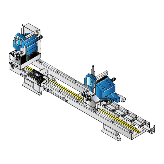
PRODUCT DESCRIPTION 3. PRODUCT DESCRIPTION 3.1 GENERAL VIEW Picture 3.1-1 General view 1. Power switch 2. Electrical panel 3. Left stable head. Head № 1. 4. Left head protective cover 5. Pneumatic clamp for left head 6. Control panel 7. Right mobile head. Head № 2. 8. -
Page 9: Technical Description
PRODUCT DESCRIPTION 3.2 TECHNICAL DESCRIPTION Cutting length size and angle degree are entered from LCD-display on control panel Automatic head position for 45° and 90 °degrees, easy adjustment for intermediate angles Possibility of manual length size adjustment Magnetic rule length control system Multilanguage support Repetitive cut program, angle cut –... -
Page 10: Installation
INSTALLATION 4. INSTALLATION ► The equipment has passed working tests of all mechanic, electric and pneumatic units at factory. All materials and the spare parts have passed the complete careful control before delivery in a transport company. ► At equipment acceptance make the control on availability/absence of any transport damages. 4.1 TRANSPORTATION INSTRUCTIONS ►... -
Page 11: Installation Settings
INSTALLATION 4.3 INSTALLATION SETTINGS ► Care should be taken for the floor to be straight and sound the machine will be positioned. Note that there will be sufficient distance around the machine in order to work safely, for easy servicing and maneuvers. -
Page 12: First Connection
INSTALLATION 4.4 FIRST CONNECTION 1. Remove the package. 2. Locate machine on an even horizotal place. 3. Connect electricity (380 V). 4. Checks the sequence of phases (3 phases + 1 neutral). 5. Connect air pressure (6-8 bar). 6. Check oil level in filter-regulator. ►... -
Page 13: Principles Of Work
PRINCIPLES OF WORK 5. PRINCIPLES OF WORK 5.1 MAIN SETTINGS ► All necessary factory options are performed on the equipment. At wear of mechanical units or details, at change of profile system it is necessary to change some options. Necessary options are given below. -
Page 14: Machine Control Elements
PRINCIPLES OF WORK 5.2 MACHINE CONTROL ELEMENTS CONTROL PANEL Picture 5.2-1 Control Panel 1. Button “Clamp” 2. Button “Pull out” 3. Switch “ Work 1 / 2 head” 4. Button “Start” cutting 5. Button “Start” Head № 2 motor 6. Button “Stop” Head № 2 motor 7. -
Page 15: Plc
PRINCIPLES OF WORK 5.3 PLC Picture 5.3-1 PLC MITSUBISHI General view A programmable logic controller (PLC) or programmable controller is a digital computer used for automation of electromechanical processes. At machine power ON, on PLC IN (Input)section following light-emitting diodes should be ON: 5, 7, 11, 15, 16. - Page 16 PRINCIPLES OF WORK Input X17 ON when thermal relay has overload Input X20 ON when Head № 2 cylinder’s sensor has signal Input X21 ON when “Forward” button pushed Input X22 ON when “Backward” button pushed Input X23 ON when “Fast” button pushed OUTPUT (Output signals) Output Y0 ON when Head №...
-
Page 17: Operation Of The Machine
PRINCIPLES OF WORK 5.4 OPERATION OF THE MACHINE ► At power supply feed on the machine display appears screen with a language selection. Select language. (EN - English) ► After language has been selected main menu screen appears MAIN MENU AUTO. -
Page 18: Manual Mode
PRINCIPLES OF WORK 5.5 MANUAL MODE MANUAL TARGET 90° 90° 1200 mm SIZE SIZE. mm 1500 Q-TY. CUTTING Q-ty. START STOP RESET Picture 5.5-1 Manual mode 1. Target. Size needed for cutting. 2. Size. Actual size on machine. 3. Head № 1 degree position. 4. - Page 19 PRINCIPLES OF WORK MANUAL TARGET 90° 90° 1200 mm SIZE SIZE. mm 1500 Q-TY. CUTTING Q-ty. START STOP RESET 1. Set the angle for stable and Head № 2s by pushing angle value (3) and (4). Head will automatically set on 45° or 90°. To set intermediate degree see 2.
-
Page 20: Automatic Mode
PRINCIPLES OF WORK 5.6 AUTOMATIC MODE AUTO. MODE MONITOR STEP 0001 FROM 0001 0010 SIZE. mm SIZE. mm 0680 1500 Q-TY. 0002 Q-TY. START STOP 0002 90° 90° Picture 5.6-1 Automatic Mode 1. From. Initial cutting step. 2. End. final cutting step. 3. - Page 21 PRINCIPLES OF WORK a. Enter step size (4). b. Enter cutting quantity (5). c. Enter angle position for both heads (7) and (6). 2. Enter parameters for next steps. Max. Step number: 2299 3. Enter initial (1) and final cutting steps (2). 4.
-
Page 22: Long Profile Cutting Over 4000 Mm
PRINCIPLES OF WORK 5.7 LONG PROFILE CUTTING over 4000 mm LONG SIZE CUTTING LEFT SAW TARG. SIZE 5000 mm 03 sec. SIZE 1500 mm RIGHT SAW 03 sec. TO END START STOP 90° 90° Picture 5.7-1 Long profile cutting mode 1. -
Page 23: Pieces Cutting
PRINCIPLES OF WORK 5.8 PIECES CUTTING PIECES CUTTING Profile SIZE 1400 mm LEFT SAW 03 sec. Cutting Q-TY. RIGHT SAW Cut. SIZE 30 mm 03 sec. TAKE START STOP 90° 90° POSITION Picture 5.8-1 Pieces cutting mode 1. Size of the profile before cutting. 2. -
Page 24: Intermediate Degree Setting
PRINCIPLES OF WORK Pneumatic cylinder of Head №1 pulls out, Head №2 slides profile to the left side for required size (4). Pneumatic cylinder of Head №1 clamps and left side cutting happens at the same time pneumatic cylinder of Head №2 pulls out and Head №2 moves left side for required size. While Head №2 is cutting, pneumatic cylinder of Head №1 pulls out and Head №2 moves left and slides profile for required size. -
Page 25: Maintenance And The Lubrication Of The Machine
MAINTENANCE AND THE LUBRICATION OF THE MACHINE 6. MAINTENANCE AND THE LUBRICATION OF THE MACHINE 1. All air and electrical energy should be disconnected before maintenance. 2. In order to disconnect the electric energy, set the power switch ‘’OFF’’ position. 3. -
Page 26: Magnetic Sensor
MAINTENANCE AND THE LUBRICATION OF THE MACHINE 6.2 MAGNETIC SENSOR ► There is a magnet inside the pneumatic cylinder and this magnet moves with the piston. ► The magnetic sensor connected to the surface of the piston open its contacts when it is effects by this magnet. -
Page 27: Pneumatic Elements
PNEUMATIC ELEMENTS Picture 6.3-1 Blade changing 7. PNEUMATIC ELEMENTS 7.1 VALVE AND CYLINDER CONTROL Picture 7.1-1 Valve and cylinder control 1. Piston cuff 2. Ring gasket ► If some operations on machine does not start to process or an air leakage occurs continuously in the valves, you should perform following: 1. -
Page 28: Cylinder Speed Adjustment
PNEUMATIC ELEMENTS 3. When air is given from B, the cylinder rod must still be giving out air, the neck seal C must be malfunctioning. If after checking them, A, B and C give out no air but there still is a leakage through the valves exhaust, check the valve. -
Page 29: Hydraulic Speed Control Cylinder
PNEUMATIC ELEMENTS 7.3 HYDRAULIC SPEED CONTROL CYLINDER (option for aluminium profiles cutting) ► The hydraulic speed control check normally couples with a pneumatic cylinder to provide uniform speed control. Picture 7.3-1 Hydraulic speed control cylinder 1. Speed control regulator 2. Reserve tank 3. -
Page 30: Cooling System
PNEUMATIC ELEMENTS 7.4 COOLING SYSTEM (option for aluminium profiles cutting) Picture 7.4-1 Cooling system 1. Switch ON / OFF for cooling system 2. Coolant Spray speed regulator 3. Spray head 4. Coolant tank 5. Pneumatic cylinder 6. Hydraulic speed control cylinder ►... -
Page 31: Filter-Regulator
PNEUMATIC ELEMENTS «British Petroleum»: Energrease L2, LS3 «Exxon»: Beacon 3 «Castrol»: Castrol LM, LMX «Agip»: Agip F1 CR MU3; Agip F1 CP FC3 «Teboil»: Multi-Purpose Grease «Texaco»: Hytex EP-2 «Unocal 76»: Multiplex Red Grease 2 «Valvoline»: General Multi Purpose Grease 7.5 FILTER-REGULATOR The first condition for a pneumatic system to function properly is to supply enough and quality pressured air. -
Page 32: Recommended Filter-Regulator Oils
PNEUMATIC ELEMENTS Oil speed adjustment: If the adjustment screw shown by number 5 is turned in the clockwise direction, the oil speed will decrease if screw is turned in the opposite direction, it starts giving oil faster to the system. Oil output should be as one drop / minute at air feeding. 7.5.1 RECOMMENDED FILTER-REGULATOR OILS 1. -
Page 33: Troubleshooting
TROUBLESHOOTING 8. TROUBLESHOOTING 8.1 ACTIONS TO BE TAKEN DURING FAILURE 1. Check the machine feeding voltage working with 3 phase of get it checked. 2. There should be 6 atmospheric pressured air. You can read this value over the regulator- filter manometer of the machine. - Page 34 TROUBLESHOOTING Button contact failure Check the button contact Right head platform is not fixed Turn ON the fixation. See page 13 Switch “Fixation” Right and the left head don’t Valve and piston failure See page 26 VALVE AND tilt to 45▫ degree CYLINDER CONTROL Mechanical pressure valve is closed...
-
Page 35: Circuit Diagrams
CIRCUIT DIAGRAMS 9. CIRCUIT DIAGRAMS 9.1 PNEUMATIC CIRCUIT DIAGRAM page. 34 / 42... - Page 36 CIRCUIT DIAGRAMS page. 35 / 42...
-
Page 37: Electric Circuit Diagram
CIRCUIT DIAGRAMS 9.2 ELECTRIC CIRCUIT DIAGRAM page. 36 / 42... - Page 38 CIRCUIT DIAGRAMS page. 37 / 42...
- Page 39 CIRCUIT DIAGRAMS page. 38 / 42...
- Page 40 CIRCUIT DIAGRAMS page. 39 / 42...
- Page 41 CIRCUIT DIAGRAMS page. 40 / 42...
-
Page 42: Warranty Terms & Conditions
WARRANTY TERMS & CONDITIONS 10. WARRANTY TERMS & CONDITIONS 1. Warranty period starts from the invoice date and it is 1 year. 2. Machine is under warranty of our company against manufacturing and material defects. Warranty exclusions: 1. Absence of warranty certificate or destruction caused on the certificate. 2.
Need help?
Do you have a question about the OMRM-133 and is the answer not in the manual?
Questions and answers