Table of Contents
Advertisement
Quick Links
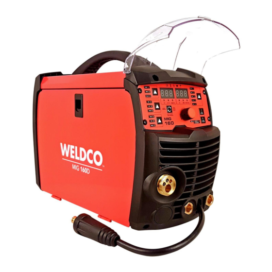
MIG160D
Inverter MIG/MMA/TIG Welder
OPERATORS MANUAL
IMPORTANT:
This manual contains important information regarding safety, operation, maintenance and storage of this product.
Before use read carefully and understand all cautions, warnings, instructions and product labels. Failure to do so
could result in serious personal injury and/or property damage.
Advertisement
Table of Contents

Subscribe to Our Youtube Channel
Related Manuals for WELDCO MIG160D


Summary of Contents for WELDCO MIG160D
- Page 1 MIG160D Inverter MIG/MMA/TIG Welder OPERATORS MANUAL IMPORTANT: This manual contains important information regarding safety, operation, maintenance and storage of this product. Before use read carefully and understand all cautions, warnings, instructions and product labels. Failure to do so could result in serious personal injury and/or property damage.
-
Page 2: Table Of Contents
TABLE OF CONTENTS Thank You For your Purchase ..............................3 Unpacking Your New Welder ................................. 3 Welding Hazards and Safety ............................... 4 Work Area ...................................... 4 Personal Protective Equipment and Clothing (PPE) ........................4 Electromagnetic and Radio Frequencies – “PACEMAKERS” ......................5 Pre-Checks ...................................... -
Page 3: Thank You For Your Purchase
Weldco would like to thank you for purchasing the MIG160D Inverter Welder. This manual is designed to guide you through using your new machine. Your Weldco inverter welder utilizes the latest in welding technology to ensure you receive professional results in a variety of applications. -
Page 4: Welding Hazards And Safety
Welding poses a variety of hazards to health and safety. Please ensure you have correct safety equipment for yourself and those within the welding area. Your local distributor will be able to assist you with the correct Weldco protective helmet and gloves. -
Page 5: Electromagnetic And Radio Frequencies - "Pacemakers
ELECTROMAGNETIC AND RADIO FREQUENCIES – “PACEMAKERS” • Avoid contact with the energized work piece. • Always ensure you have adequate protection from electrocution and burns. • Since the welder owns strong electromagnetic and radio frequencies. Persons fitted with “PACEMAKERS” or similar devices MUST consult their doctor before turning on the welder. -
Page 6: Technical Description
INPUT PLUG The MIG160D is fitted with a 10amp plug. This machine is designed to work with 10amp domestic wall sockets. It is important that the machine is plugged directly into the mains plug. If an extension cord must be used a minimum 2.5mm wire thickness is require and no more than 10m in length. -
Page 7: Machine Layout
MACHINE LAYOUT 1. Female Euro Connector 2. Wire Feed Compartment door. 3. Negative Terminal 4. Positive Terminal 5. Polarity Cable INSIDE – WIRE FEED COMPARTMENT 22. Spool Retainer Nut 23. Spool Brake Tensioner 24. Tensioner Adjuster 25. Tensioner Arm 26. Outer guide Tube 27. - Page 8 CONTROL PANEL LAYOUT 6. Voltage Display 7. Amperage Display 8. Wire Selector 9. Gas Test 10. Wire Feed 11. Main Adjustment 12. Step Selector 13. Welding Process Selector 14. Torch Control & VRD 15. Gas selector 16. Voltage 17. Voltage Adjust 18.
-
Page 9: Mig Welding Setup
SETUP FOR MIG WELDING Smooth consistent wire feed is critical to achieve professional results. FITTING THE WIRE 5KG/200MM DIAMETER WIRE SPOOL 1. Open the cover door (2) for the wire feed compartment. Remove the wire spool retaining nut (22) by threading the retainer clockwise. - Page 10 FITTING THE WIRE 1KG/100MM DIAMETER WIRE SPOOL 1. Open the cover door (2) for the wire feed compartment. Remove the tensioning nut, washer’s and spring. Slide off spool holder – keep in a safe place. 2. Fit the 1Kg/100mm diameter wire spool on the shaft. Ensure the end of the wire feeds towards the drive rollers from the bottom of the spool.
- Page 11 WIRE FEEDER 4. Release the wire feeder tensioner arm (25) by pulling forward the tension adjustment knob (24). Check the drive roller matches the wire type and wire diameter (size is stamped on the side of the roller). “V” groove roller for solid hard gas shield wires – Mild steel and Stainless Steel. “Knurled”...
-
Page 12: Gasless Mig Welding Setup
SETUP FOR GASLESS MIG WELDING 5. Polarity Cable 4. Positive Earth Please ensure you have all relevant safety equipment and PPE ready. Connect the MIG torch male Euro Connector to the female Euro Connector (1) on the front of the power source. Secure hand tight. - Page 13 (effectively increasing wire speed). Push the button (11) again to lock in your setting. As your MIG160D has an MCU (computer chip) your setting will be saved until next time. 13. To adjust your voltage and wire speed individually, select SP on the wire size selector (8).
- Page 14 14. To increase or decrease wire speed, adjust the main adjustment dial (11). To switch to voltage adjustment, press the main adjustment dial (11). Adjust the main adjustment dial to increase or decrease voltage as required. Press the main adjustment dial again to switch back to wire speed adjustment.
-
Page 15: Gas Mig Welding Setup
5. Polarity Cable Please ensure you have all relevant safety equipment and PPE ready. 1. Connect the optional Weldco Argon Regulator (WDC0812) to the argon cylinder or CO2 cylinder and connect the gas line to the regulator. 2. Connect the gas line from the regulator to the gas inlet (31) 3. - Page 16 Select MIG on the welding process selector (13) Select torch function (14) • 2T for standard torch operation. Press and hold the trigger to start the weld, continue to hold trigger whilst welding. Releasing the trigger stop welding. • 4T is used for long welding runs or for out of position welding where holding the trigger on is difficult.
- Page 17 (effectively increasing wire speed). Push the button (11) again to lock in your setting. As your MIG160D has an MCU (computer chip) your setting will be saved until next time. To adjust your voltage and wire speed individually, select SP on the wire size selector (8).
-
Page 18: Mma (Stick) Welding Setup
SETUP FOR MMA (STICK) WELDING 2. Positive Electrode Holder 1. Negative Earth Please ensure you have all relevant safety equipment and PPE ready. This setup is for the most common electrode positive setting for General purpose rods. Please check your electrode packaging to confirm. - Page 19 Once the machine has powered up press the welding process selector (13) to select MMA. 19 20 Your Weldco Inverter welder is fitted with a “Voltage Reduction Device” (VRD). The VRD reduces the open circuit voltage to safer levels. The VRD default is OFF.
-
Page 20: Dc Lift Tig Welding Setup
Failure to do so will reduce your welding performance. Connect the optional Weldco VALVE TIG torch (WDC0818) into the NEGATIVE (3) terminal on the front of the machine. Ensure that the plug is secure in the socket to reduce any chance of arcing from loose connection Connect the optional Weldco Argon Regulator (WDC0812) to the argon cylinder and connect the gas line from the TIG torch to the regulator. - Page 21 Once the machine has powered up, press the welding process selector (13) to select TIG. Your Weldco Inverter welder is fitted with a “Voltage Reduction Device” (VRD). The VRD is not used for TIG welding. Adjust the welding current by turning the main adjustment dial (11) to the relevant amperage level for the Tungsten size and material.
-
Page 22: Maintenance
This warranty does not cover freight or goods serviced by un-authorized personnel. Weldco NZ will inspect your power source for faulty material or workmanship and will only be replaced if repair is not possible. Note: The warranty is for the power source only. Leads and accessories are consumables and only replaced for failures due to... -
Page 23: Troubleshooting
TROUBLESHOOTING POWER SUPPLY Part Check Remarks Operation, replacement and installation of Switch. Control panel If no power, see approved service agent. Switch on the power and check if the power indicator is on. Check if the fan is functioning and the sound If the fan doesn’t work or the sound is abnormal. -
Page 24: Wire Feeder
Part Check Remarks Make sure that the diffuser of required Defection weld or even the damage of torch Diffuser specification is occurs due to the non-installation of diffuser or installed and is the unqualified diffuser. unblocked. WIRE FEEDER Part Check Remarks Check the tensioner adjustment dial is... - Page 25 The power indicator light will not turn on. Allow the machine to rest for a few minutes and normal operation should continue. If this does not rectify the issue, please contact your approved WELDCO Technician.
- Page 26 NOTES...
- Page 27 NOTES...
- Page 28 WELDCO NEW ZEALAND Christchurch 8024 New Zealand www.weldco.co.nz Made in China © 2021...
Need help?
Do you have a question about the MIG160D and is the answer not in the manual?
Questions and answers