Table of Contents
Advertisement
Quick Links
MIG145
Inverter MIG/MMA Welder
OPERATORS MANUAL
IMPORTANT: This manual contains important information regarding safety, operation, maintenance and storage of this product.
Before use read carefully and understand all cautions, warnings, instructions and product labels. Failure to do so could result in
serious personal injury and/or property damage.
Advertisement
Table of Contents

Related Manuals for WELDCO MIG145


Summary of Contents for WELDCO MIG145
- Page 1 MIG145 Inverter MIG/MMA Welder OPERATORS MANUAL IMPORTANT: This manual contains important information regarding safety, operation, maintenance and storage of this product. Before use read carefully and understand all cautions, warnings, instructions and product labels. Failure to do so could result in...
-
Page 2: Table Of Contents
TABLE OF CONTENTS Thank You For your Purchase ..............................3 Unpacking Your New Welder ................................. 3 Welding Hazards and Safety ............................... 4 Work Area ...................................... 4 Personal Protective Equipment and Clothing (PPE) ........................4 Electromagnetic and Radio Frequencies – “PACEMAKERS” ......................5 Pre-Checks ...................................... -
Page 3: Thank You For Your Purchase
Weldco would like to thank you for purchasing the MIG145 Inverter Welder. This manual is designed to guide you through using your new machine. Your Weldco inverter welder utilizes the latest in welding technology to ensure you receive excellent results in a variety of applications. -
Page 4: Welding Hazards And Safety
Welding poses a variety of hazards to health and safety. Please ensure you have correct safety equipment for yourself and those within the welding area. Your local distributor will be able to assist you with the correct Weldco protective helmet and gloves. -
Page 5: Electromagnetic And Radio Frequencies - "Pacemakers
ELECTROMAGNETIC AND RADIO FREQUENCIES – “PACEMAKERS” • Avoid contact with the energized work piece. • Always ensure you have adequate protection from electrocution and burns. • Since the welder owns strong electromagnetic and radio frequencies. Persons fitted with “PACEMAKERS” or similar devices MUST consult their doctor before turning on the welder. -
Page 6: Technical Description
INPUT PLUG The MIG145 is fitted with a 10amp plug. This machine is designed to work with 10amp domestic wall sockets. It is important that the machine is plugged directly into the mains plug. If an extension cord must be used a minimum 2.5mm wire thickness is required and no more than 10m in length. -
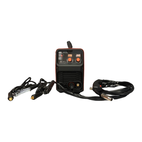
Page 7: Machine Layout
MACHINE LAYOUT 1. Positive Terminal 2. Negative Terminal 3. Polarity Cable INSIDE – WIRE FEED COMPARTMENT 4. Spool Retaining Nut 5. Tension Adjuster 6. Tensioner Arm 7. Roller Retainer Bolt 8. Drive Roller 9. Inlet Guide Tube 10. Spool Brake Tensioner Spring REAR PANEL 20. - Page 8 CONTROL PANEL LAYOUT Voltage Display 12. Amperage Display 13. Amperage Control 14. Voltage Control 15. Welding Process selector 16. Voltage Reduction Device. (VRD) 17. MMA (Arc Welding). 18. MIG Synergic (SYN) or Manual 19. Thermal Overload Light Electrode Holder Earth Clamp and lead MIG TORCH EXPLODED Tip Adapter Tip Adapter Spring...
- Page 9 BLANK PAGE - NOTES...
-
Page 10: Mig Welding Setup
SETUP FOR GAS OR GASLESS MIG WELDING Smooth consistent wire feed is critical to achieve professional results. FITTING THE WIRE • Open the side cover door for the wire feed compartment. Remove the wire spool retaining nut (4), tensioner spring and flange. - Page 11 • Set the spool brake tensioner by tightening or loosening the wire spool retaining nut. Set the spool brake tension so that the spool can rotate freely, without continuing to rotate once the wire feed stops. Check performance from time to time to ensure that the wire is feeding correctly, especially as the wire spool empties. WIRE FEEDER •...
-
Page 12: Gasless Mig Welding Setup
SETUP FOR GASLESS MIG WELDING 3. Polarity Cable Negative Terminal (2) 1. Earth Cable - Positive Terminal Please ensure you have all relevant safety equipment and PPE ready. • Check that the correct gasless (Flux cored) wire, drive roller (8) and welding tip are fitted. •... - Page 13 • Your MIG145 MIG synergic mode, removes the guess work out of selecting the right combination of VOLTAGE and WIRE SPEED. Once you have selected MIG Synergic increasing or decreasing dial (13) will adjust both the voltage (heat) and Amperage (wire speed m/min).
-
Page 14: Gas Mig Welding Setup
Negative Terminal (3) Please ensure you have all relevant safety equipment and PPE ready. • Connect the optional Weldco Argon Regulator (WDC0812) to the argon cylinder or CO2 cylinder and connect the gas line to the regulator. • Connect the gas line from the regulator to the gas inlet on the back panel of the welder. - Page 15 • Your MIG145 MIG synergic mode, removes the guess work out of selecting the right combination of VOLTAGE and WIRE SPEED. Once you have selected MIG Synergic increasing or decreasing dial (13) will adjust both the voltage (heat) and Amperage (wire speed m/min).
-
Page 16: Mma (Stick) Welding Setup
SETUP FOR MMA (STICK) WELDING 3. Earth Cable - Negative Terminal 2. Electrode Holder Positive Terminal Please ensure you have all relevant safety equipment and PPE ready. This setup is for the most common electrode positive setting for General purpose rods. Please check your electrode packaging to confirm. - Page 17 Once the machine has powered up press the welding process selector (11) to select MMA. • Your Weldco Inverter welder is fitted with a “Voltage Reduction Device” (VRD) (16) The VRD reduces the open circuit voltage to safer levels. The VRD default is OFF. To activate the VRD press the welding process selector (15) to select VRD.
-
Page 18: Maintenance
This warranty does not cover freight or goods serviced by un-authorized personnel. Weldco NZ will inspect your power source for faulty material or workmanship and will only be replaced if repair is not possible. Note: The warranty is for the power source only. Leads and accessories are consumables and only replaced for failures due to... -
Page 19: Troubleshooting
TROUBLESHOOTING POWER SUPPLY Part Check Remarks Operation, replacement, and installation of Switch. Control panel If no power, see approved service agent. Switch on the power and check if the power indicator is on. Check if the fan is functioning and the sound generated is If the fan does not work or the sound is normal. -
Page 20: Wire Feeder
The power indicator light will not turn on. Allow the machine to rest for a few minutes and normal operation should continue. If this does not rectify the issue, please contact your approved WELDCO Technician. - Page 21 NOTES...
- Page 22 NOTES...
- Page 23 NOTES...
- Page 24 WELDCO NEW ZEALAND Christchurch 8024 New Zealand www.weldco.co.nz Made in China © 2021...
Need help?
Do you have a question about the MIG145 and is the answer not in the manual?
Questions and answers