Table of Contents
Advertisement
Quick Links
Advertisement
Table of Contents

Related Manuals for Magtek INTELLISTRIPE 380

Summary of Contents for Magtek INTELLISTRIPE 380
-
Page 1: Technical Reference Manual
INTELLISTRIPE 380 USB/RS-232 DESKTOP MOTORIZED READER-ENCODER TECHNICAL REFERENCE MANUAL Manual Part Number 99875275-3 AUGUST 2007 REGISTERED TO ISO 9001:2000 1710 Apollo Court Seal Beach, CA 90740 Phone: (562) 546-6400 FAX: (562) 546-6301 Technical Support: (651) 415-6800 www.magtek.com... - Page 2 2001-2007 ® MagTek , Inc. Printed in the United States of America © 1998 by Compaq Computer REVISIONS Notes Initial Release Editorial throughout. Sec 1, Configurations: changed 2 part numbers, clarified power supply description; Features: removed JIS, to optional SAM and TRSM added “contact for further info”; clarified Rotary Pulse Generator;...
-
Page 3: Software License Agreement
REGISTERED TO ISO 9001:2000 MagTek Part Number 99875275-1 1710 Apollo Court, Seal Beach, CA 90740 25 February 2003 Voice: 562-546-6400 Fax: 562-546-6301 SOFTWARE LICENSE AGREEMENT IMPORTANT: YOU SHOULD CAREFULLY READ ALL THE TERMS, CONDITIONS AND RESTRICTIONS OF THIS LICENSE AGREEMENT BEFORE INSTALLING THE SOFTWARE PACKAGE. YOUR INSTALLATION OF THE SOFTWARE PACKAGE PRESUMES YOUR ACCEPTANCE OF THE TERMS, CONDITIONS, AND RESTRICTIONS CONTAINED IN THIS AGREEMENT. -
Page 4: Fcc Warning Statement
FCC WARNING STATEMENT This equipment has been tested and found to comply with the limits for a Class A digital device, pursuant to Part 15 of FCC Rules. These limits are designed to provide reasonable protection against harmful interference when the equipment is operated in a commercial environment. This equipment generates, uses, and can radiate radio frequency energy and, if not installed and used in accordance with the instruction manual, may cause harmful interference to radio communications. -
Page 5: Table Of Contents
SECTION 1. FEATURES AND SPECIFICATIONS... CONFIGURATIONS ... FEATURES... APPLICABLE DOCUMENTS ... Standards ... MagTek Documents ... SOFTWARE ACCESSORIES ... COMPONENTS ... Motorized Card Transport... 3 Lead-in Roller System...3 Front Opto-Sensor ...3 Encode Opto-Sensor...3 Card-Landed Mechanical Switch Sensor ...3 Spring-Loaded Card Registration Guide(s)... Ability To Transport 0.010 ”to 0.035”... - Page 6 Flange... MagTek Mounting Plate... REAR PANEL AND CABLE CONNECTIONS... SECTION 3. OPERATION AND MAINTENANCE ... OPERATION... PREVENTIVE MAINTENANCE... CORRECTIVE MAINTENANCE... Ejector Rod for Card Jams ... APPENDIX A. DIMENSIONS FOR MOUNTING ... MOUNTING ... Footpad Mounting... Mounting Hole Screws... Lock-in-place-slots... Flange...
- Page 7 Figure 2-3. Rear Panel and Cover------------------------------------------------------------------------------------------ Figure 2-4. Cable Connections - RS-232 --------------------------------------------------------------------------------- Table 2-1. Pin List for IntelliStripe 380 to Host PC Cable P/N 16051417 ----------------------------------------- Figure 2-5. Cable Connections - USB ------------------------------------------------------------------------------------- Table 2-2. Cable Connections – USB Signal ---------------------------------------------------------------------------- Table 2-3.
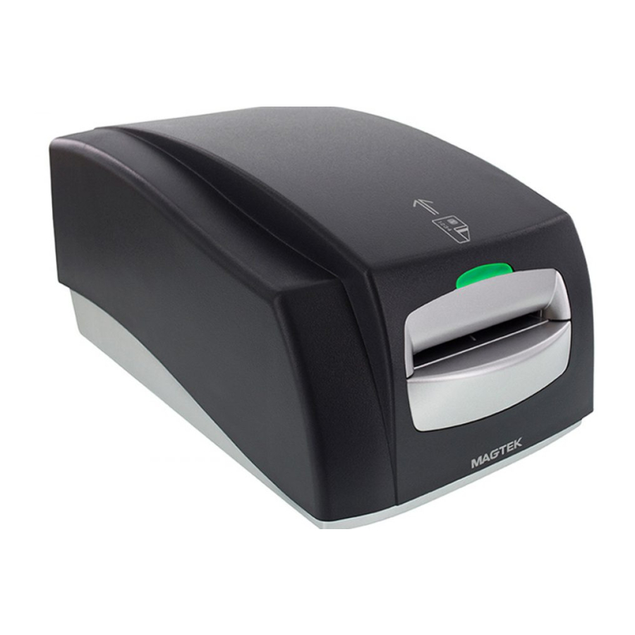
- Page 8 Figure 1-1. IntelliStripe 380 viii...
-
Page 9: Section 1. Features And Specifications
SECTION 1. FEATURES AND SPECIFICATIONS ® The IntelliStripe 380, Desktop Motorized Reader-Encoder reads and encodes magnetic-stripe cards and smartcards. CONFIGURATIONS Part numbers and descriptions for the basic configuration are as follows: 16050408 IntelliStripe 380 16050410 IntelliStripe 380, Magstripe Only 16051417 I/O Cable, 10-pin RJ45 connector connects to host 9-pin connector with 12V/Ground connector for Power Supply. -
Page 10: Applicable Documents
EMV 2000 MagTek Documents MCP Serial Transport Protocol, P/N 99875163 IntelliStripe 380, Command Reference Manual, P/N 99875217 SOFTWARE ACCESSORIES The following Software Modules may be required and will assist in the development of application software. In addition, this software can provide an initial test platform for checkout of the IntelliStripe 380. -
Page 11: Motorized Card Transport
Section 1. Features and Specifications Motorized Card Transport The Card Transport is based on an existing MagTek magstripe/encode module. This module incorporates the following features: Lead-in Roller System The primary purpose of the Lead-in Roller System is to grab the card from the user during card insertion and to make sure the card is mechanically under motor control before reaching the read/write head and its associated drive rollers. -
Page 12: Spring-Loaded Card Registration Guide(S)
IntelliStripe 380 Spring-Loaded Card Registration Guide(s) The spring-loaded guide ensures that the reference edge of the card is mechanically referenced to the magnetic read/write head, so that the magnetically encoded track data is physically located on the magstripe in accordance with the specifications of ISO 7811. -
Page 13: Smartcard
Direction of Magnetic Read: The ISO 7810 and 7811 specifications allow for bidirectional magnetic reading of the card. As such, the Reader provides services that allow the card to be read in either direction. Read Formats: In addition to reading cards that meet the ISO 7810 and 7811 specifications, the Reader reads AAMVA drivers license cards. -
Page 14: Cable Management
IntelliStripe 380 Cable Management The following provisions are made for communication and power lines: • Polarization and locking of cable connectors • Strain relief of cables • Wire routing functionality • RJ series connectors for main and auxiliary RS-232 interfaces. -
Page 15: Host Serial Port
RAM Space: 40 K bytes ROM Space: ROM Flash: Main Program Memory: 512 K Bytes Boot Loader Memory: 24 K Bytes Configuration Memory: 8 K Bytes Host Serial Port The RS-232 Host Serial Port provides serial communications between the Reader/Encoder and the Host Computer. -
Page 16: Opto-Sensor Inputs
IntelliStripe 380 Opto-Sensor Inputs The Main PCB provides inputs for the three opto-sensors (Front, Encode, and Rear). Rotary Pulse Generator The Main PCB provides input for the MagTek 75/210 bpi Rotary Pulse Generator (RPG). External SAM Ranch Interface, Optional The Main PCB provides resources for interconnect, securement, and power of an optional SAM Ranch PCB. -
Page 17: External Auto-Ranging Power Pack
Section 1. Features and Specifications External Auto-Ranging Power Pack The Reader/Encoder is powered from an external power-pack, which is located near the Host Computer System. Power is routed to the Reader/Encoder through the Host RS-232 cable. Auto-Ranging Input The external power pack features an Auto-ranging AC input that allows for direct connection to either a 100 VAC or 220 VAC, 50 to 60 Hz. -
Page 18: Specifications
IntelliStripe 380 SPECIFICATIONS The Specifications are listed in Table 1-1. MSR Read-data Format Specifications Supported Encode Coercivity Ranges Input Voltage Current Draw MTBF Card Speed Interface Dimensions Length Width Height Weight Temperature Operating Storage Humidity Operating Storage Altitude Operating Storage Table 1.1. -
Page 19: Section 2. Installation
MOUNTING The bottom of the unit is shown in Figure 2-1 and 2-2. The IntelliStripe 380 may be mounted in one of three ways: 1) foot pads, 2) set of mounting holes for 3 screws (4 x 40), and 3) 4 lock-in- place slots. -
Page 20: Rear Panel And Cable Connections
Figure 2-2. Dimensions for Mounting Holes for Lock-in-Place Slots REAR PANEL AND CABLE CONNECTIONS To access the rear panel and cable connections on the IntelliStripe 380, remove the rear panel cover, shown in Figure 2-3, by squeezing the two mounting clips on the cover as indicated in the illustration. -
Page 21: Figure 2-3. Rear Panel And Cover
Card Ejector Rod Connect the Host PC cable (P/N 16051417) to the RS-232 connector on the IntelliStripe 380 as shown in Figure 2-4 for the RS-232 connection. Connect the Host PC Cable to the PC. Connect the Power Supply Cord (part of P/N 64300091) to the Host PC cable. -
Page 22: Table 2-1. Pin List For Intellistripe 380 To Host Pc Cable P/N 16051417
Cable P/N 16051417 Figure 2-4. Cable Connections - RS-232 Table 2-1 lists the pins for the host cable P/N 16051417. Table 2-1. Pin List for IntelliStripe 380 to Host PC Cable P/N 16051417 10P10C RJ Plug PWR GND SIG GND... -
Page 23: Table 2-2. Cable Connections – Usb Signal
Cable connections for the USB are Shown in Figure 2-5, and the pin lists are shown in Table 2-2 and Table 2-3. IntelliStripe 380 Back Panel Pin 10 Pin 1 Power Supply (with cable) Table 2-2. Cable Connections – USB Signal... -
Page 24: Figure 2-6. Rear Panel Cover Replaced – Rs-232 Connection
IntelliStripe 380 Table 2-3. Cable Connections – USB Power P3 – 2.5 mm Power Jack Shell Center Pin Shell Center Pin Center Pin Check all connectors to ensure they are properly connected. Replace the Rear Panel Cover by inserting the mounting clips into the guide slots and press into the attachment slots as indicated in Figure 2-3. -
Page 25: Figure 2-7. Rear Panel Cover Replaced – Usb Connection
Section 2. Installation Ejector Rod Hole For Card Removal Rear Panel Cover Power And USB Cable P/N 16051422 Figure 2-7. Rear Panel Cover Replaced – USB Connection Plug in the power supply into a wall receptacle. - Page 26 IntelliStripe 380...
-
Page 27: Section 3. Operation And Maintenance
SECTION 3. OPERATION AND MAINTENANCE The operation of the unit includes inserting and removing the card. Maintenance includes keeping the unit clean and removing jammed cards from the unit. OPERATION The card is inserted with the magnetic stripe down and to the right as illustrated in Figure 3-1. Perform any tasks on the PC as directed. -
Page 28: Figure 3-2. Ejector Rod Removal From Storage
IntelliStripe 380 Shut power off by unplugging the power supply (Figure 2-4), and remove the card with the Rod as follows: 1. Remove the Rear Panel Cover to access the Ejector Rod as indicated in Figure 3-2. Ejector Rod Hole For Card Removal Figure 3-2. -
Page 29: Mounting Hole Screws
MOUNTING The bottom of the unit is shown in Figure 2-1 and 2-2. The IntelliStripe 380 may be mounted in one of three ways: 1) foot pads, 2) set of mounting holes for 3 screws (4 x 40), and 3) 4 lock-in- place slots. -
Page 30: Figure A-1. Mounting Dimensions 1
IntelliStripe 380 Figure A-1. Mounting Dimensions 1... -
Page 31: Figure A-2. Mounting Dimensions 2
Appendix A. Dimensions for Mounting Figure A-2. Mounting Dimensions 2... -
Page 32: Figure A-3. Magtek Mounting Plate, I380, 1
IntelliStripe 380 Figure A-3. MagTek Mounting Plate, I380, 1... -
Page 33: Figure A-4. Magtek Mounting Plate, I380, 2
Appendix A. Dimensions for Mounting Figure A-4. MagTek Mounting Plate, I380, 2... - Page 34 Appendix A. Dimensions for Mounting...
Need help?
Do you have a question about the INTELLISTRIPE 380 and is the answer not in the manual?
Questions and answers