Advertisement
Table of Contents
- 1 Lift Switch Operation
- 2 Dump Switch Operation
- 3 Lift Switch Operation (Series Wound Motor S/N 2008-1508 & ON)
- 4 Dump Switch Operation (Series Wound Motor S/N 2008-1508 & ON)
- 5 Hi-Dump Attachment Adjustments
- 6 Hydraulic Pressure Test Manifold
- 7 Electrical Schematic (Walker HD8400)
- 8 Electrical Schematic
- Download this manual
Lift Switch Operation
1. Pump runs.
2. The valve solenoids do not activate. Oil goes thru the valves to the cylinder.
3.
The relays are not energized. Current goes thru in their normal position.
Dump Switch Operation
1.
Both relays are energized.
2.
Both valve solenoids are activated.
3.
The pump runs.
If the switches are good suspect one of the relays. Even though we have not seen any of the
relays fail to date we are going to higher rated relays . When you engage the dump switch
you should feel the relays energize.
If the pump does not run most likely the problem is a relay.
If the pump runs but the cylinder won't move the problem could be a stuck valve or one of the
solenoids on the valves not activating.
Another area to look at is the terminals in the relay plugs. They push on very hard and
sometimes a terminal will back out as the plug goes on.
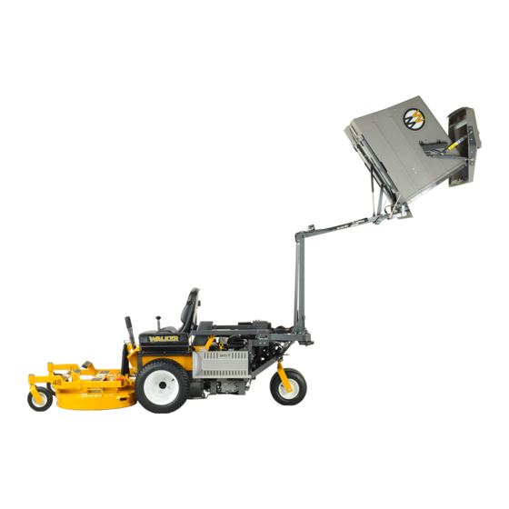
Hi-Dump Operation
April 5, 2005
Advertisement
Table of Contents

Subscribe to Our Youtube Channel
Related Manuals for Walker Hi-Dump


Summary of Contents for Walker Hi-Dump
- Page 1 Hi-Dump Operation April 5, 2005 Lift Switch Operation 1. Pump runs. 2. The valve solenoids do not activate. Oil goes thru the valves to the cylinder. The relays are not energized. Current goes thru in their normal position. Dump Switch Operation Both relays are energized.
- Page 2 Hi-Dump Operation Series Wound Motor S/N 2008-1508 & ON Lift Switch Operation 1. SPDT switch controls direction of pump motor rotation. 2. Valve block spools do not shift and oil is directed to the lift cylinder. 3. Pump rotation dictates the cylinder direction.
- Page 3 HI-DUMP ATTACHMENT ADJUSTMENTS ® 1. Adjust the lift section of the Hi-Dump by adjusting the two long control rods with ball joints on the ends. These ball joints have LH and RH threads. To adjust, loosen the jam nuts on each one and turn the rods. They must be adjusted equally.
- Page 4 Hydraulic Pressure Test Manifold Part # Discription 25.901-5000#-1/4LM NOSHOK Pressure Gauge PN400S PARKER Needle Valve 1/4 MMS-S PARKER Branch Tee, NPT 4-4 FLO-S PARKER Male O-Ring Face Seal to Male NPT Straight Adapter Optional, Customer Can use existing plumbing if available: 60-JC-JC-4-4-4-16.00"...
- Page 5 WALKER HD8400 ELECTRICAL SCHEMATIC GRN/ BLU/ RELAY - A RELAY - B Hydraulic GRN/ Hydraulic Hydraulic Pump Valve Valve Block Block BLU/ Coil Coil LIFT DUMP SWITCH SWITCH DOWN DOWN JUNCTION JUNCTION 40 AMP CIRCUIT BREAKER...
- Page 6 WALKER HD8400 Beginning S/N 2008-1708 ELECTRICAL SCHEMATIC Hydraulic Hydraulic Valve Valve Block Block Coil Coil RED/YEL Hydraulic Pump DUMP LIFT SWITCH SWITCH RED/ RED/ RED/ DOWN DOWN JUNCTION JUNCTION 40 AMP CIRCUIT BREAKER To Red Wire on Time-Delay Harness...
Need help?
Do you have a question about the Hi-Dump and is the answer not in the manual?
Questions and answers