Advertisement
Preface
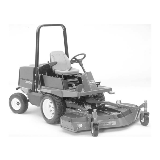
The purpose of this publication is to provide the service
technician with information for troubleshooting, testing,
and repair of major systems and components on the
Groundsmaster 3000 and 3000–D.
REFER TO THE TRACTION UNIT AND CUTTING
UNIT OPERATOR'S MANUALS FOR OPERATING,
MAINTENANCE AND
TIONS. Space is provided in Chapter 2 of this book to
insert the Operator's Manuals and Parts Catalogs for
your machine. Replacement Operator's Manuals are
available by sending complete Model and Serial Num-
ber to:
The Toro Company
8111 Lyndale Avenue South
Bloomington, MN 55420
The Toro Company reserves the right to change product
specifications or this publication without notice.
Groundsmaster
ADJUSTMENT
INSTRUC-
E The Toro Company – 1997, 1998, 2003, 2004
R
3000/3000–D
This safety symbol means DANGER, WARN-
ING, or CAUTION, PERSONAL SAFETY
INSTRUCTION. When you see this symbol,
carefully read the instructions that follow.
Failure to obey the instructions may result in
personal injury.
NOTE: A NOTE will give general information about the
correct operation, maintenance, service, testing or re -
pair of the machine.
IMPORTANT: The IMPORTANT notice will give im -
portant instructions which must be followed to pre-
vent damage to systems or components on the
machine.
Part No. 96890SL Rev. C
Service Manual
Advertisement
Chapters
Troubleshooting

Related Manuals for Toro Groundsmaster 3000


Summary of Contents for Toro Groundsmaster 3000
- Page 1 Bloomington, MN 55420 portant instructions which must be followed to pre- vent damage to systems or components on the The Toro Company reserves the right to change product machine. specifications or this publication without notice. E The Toro Company – 1997, 1998, 2003, 2004...
- Page 2 Groundsmaster 3000/3000–D...
-
Page 3: Table Of Contents
Adjustments ....... 8 – 2 Service and Repairs ......8 – 3 Groundsmaster 3000/3000–D... - Page 4 Groundsmaster 3000/3000–D...
- Page 5 Chapter 10 – Contour 82I Cutting Unit Groundsmaster 3000 ..... . 12 – 3 Specifications ......10 – 2 Adjustments .
- Page 6 Groundsmaster 3000/3000–D...
-
Page 7: Safety Instructions
While Operating ......2 Safety Instructions The GROUNDSMASTER 3000 and 3000-D was tested and certified by TORO for compliance with the B71.4—1990 specifications of the American National CAUTION Standards Institute. Although hazard control and acci... - Page 8 19. If engine stalls or machine loses headway and can can provide additional braking. not make it to the top of a slope, do not turn machine around. Always back slowly straight down the slope. Safety Groundsmaster 3000/3000–D Page 1 – 2...
- Page 9 To ensure optimum performance and continued safety certification 33. Make sure all hydraulic line connectors are tight, of the machine, use genuine TORO replacement parts and all hydraulic hoses and lines are in good condition and accessories. Replacement parts and accessories before applying pressure to the system.
-
Page 10: Safety And Instruction Decals
Safety and Instruction Decals (Groundsmaster 3000) The following safety and instruction decals are mounted on the traction unit. If any decal becomes damaged or illeg ible, install a new decal. Part numbers are listed below or in your parts catalog. - Page 11 Safety and Instruction Decals (Groundsmaster 3000–D) The following safety and instruction decals are mounted on the traction unit. If any decal becomes damaged or illeg ible, install a new decal. Part numbers are listed below or in your parts catalog.
- Page 12 On left Rear Top of Deck On Each Corner Of Under Cover Under Cover Cutting Unit (Part No. 94–3392) (Part No. 93–4691) (Part No. 93–7815) Replaces Decal Part No. 43–8480 for CE Safety Groundsmaster 3000/3000–D Page 1 – 6 Rev. A...
- Page 13 (Part No. 93–4894) Replaces Decal Part No. 66–1340 for CE On Deck Channels, Under Covers (Part No. 93–7814) On Each Castor Arm (Part No. 93–4690) Replaces Decal Part No. 85–6410 for CE Groundsmaster 3000/3000–D Safety Page 1 – 7 Rev. A...
- Page 14 On Top of Rear Castor (Chamber 1) (Part No. 95–6003) On Side of Rear Support (Chamber 3) On Left Lift Arm On Right Lift Arm (Part No. 95–6004) (Part No. 95–6008) (Part No. 95–6005) Safety Groundsmaster 3000/3000–D Page 1 – 8...
- Page 15 (Part No. 93–4691) (Part No. 93–7815) Replaces Decal Part No. 43–8480 for CE On Deck Channels, Under Covers (Part No. 93–7814) On Front Deck Hanger (Part No. 93–4690) Replaces Decal Part No. 85–6410 for CE Groundsmaster 3000/3000–D Safety Page 1 – 9...
- Page 16 Deck (Part No. 93–0299) (Part No. 43–8480) On Each Corner Of Deck (Part No. 93–7815) On Right Rear Top of Deck Under Cover Replaces Decal Part No. (Part No. 85–6120) 43–8480 for CE Safety Groundsmaster 3000/3000–D Page 1 – 10...
- Page 17 (Part No. 85–6410) Replaces Decal Part No. 66–1340 for CE On Right Rear Top of Deck On left Rear Top of Deck On Front of Deck (Part No. 94–3392) (Part No. 93–4691) (Part No. 88–1270) Groundsmaster 3000/3000–D Safety Page 1 – 11...
- Page 18 Safety Groundsmaster 3000/3000–D Page 1 – 12...
-
Page 19: Product Records
Record information about your Groundsmaster 3000 or Insert Operator’s Manuals and Parts Catalogs for your 3000–D on the OPERATION AND SERVICE HISTORY Groundsmaster 3000 or 3000–D at the end of this sec REPORT form. Use this information when referring to tion. -
Page 20: Equivalents And Conversions
Equivalents and Conversions Product Records and Maintenance Groundsmaster 3000/3000–D Page 2 – 2... -
Page 21: Torque Specifications
Torque Specifications Groundsmaster 3000/3000–D Product Records and Maintenance Page 2 – 3... - Page 22 800 800 400 Product Records and Maintenance Groundsmaster 3000/3000–D Page 2 – 4 Rev. A...
-
Page 23: Lubrication
Pivots (5), Traction pedal (In square tube under floor plate) (1) (Fig. 5) and Lift arm pivot (2) (Fig. 6). Figure 4 Figure 1 Figure 5 Figure 6 Figure 2 Groundsmaster 3000/3000–D Product Records and Maintenance Page 2 – 5... -
Page 24: Cutting Units
Lubricate fittings immediately after ev machine, stop engine and remove key from the ery washing, regardless of the interval listed. switch. Guardian 84 Recyler Cutting Unit Figure 7 Product Records and Maintenance Groundsmaster 3000/3000–D Page 2 – 6... - Page 25 Rear Discharge 84 Cutting Unit Figure 8 Contour 82 Cutting Unit Figure 9 Groundsmaster 3000/3000–D Product Records and Maintenance Page 2 – 7...
- Page 26 Guardian 72 Recycler Cutting Unit Figure 10 Rear Discharge 72 Cutting Unit Figure 11 Product Records and Maintenance Groundsmaster 3000/3000–D Page 2 – 8...
-
Page 27: Equipment Operation And Service History Reports
EQUIPMENT OPERATION AND SERVICE HISTORY REPORT GROUNDSMASTER 3000 TORO Model and Serial Number: ______________–______________ Engine Numbers: _____________________________ Transmission Numbers: _____________________________ Drive Axle(s) Numbers: _____________________________ Date Purchased: _____________________________ Warranty Expires____________ Purchased From: _____________________________ _____________________________ _____________________________ Contacts: Parts _____________________________ Phone____________________ Service _____________________________ Phone____________________... - Page 28 Groundsmaster 3000 Maintenance Schedule Minimum Recommended Maintenance Intervals Maintenance Procedure Maintenance Interval & Service Every Every Every 800hrs Every 400hrs Lubricate All Grease Fittings Every 200hrs 100hrs 50hrs Inspect Air Filter Check Battery Level/Cable Connections Check Cutting Unit Gearbox Oil Level...
- Page 29 Groundsmaster 3000 Daily Maintenance Check List Unit Designation: ____________ TORO ID #: ________–________ Daily Maintenance: (duplicate this page for routine use) Check proper section of Operator’s Manual for fluid specifications Daily Maintenance Check For Week Of _________________ Maintenance Check Item...
- Page 30 Product Records and Maintenance Groundsmaster 3000/3000–D Page 2 – 12...
- Page 31 EQUIPMENT OPERATION AND SERVICE HISTORY REPORT GROUNDSMASTER 3000–D TORO Model and Serial Number: ______________–______________ Engine Numbers: _____________________________ Transmission Numbers: _____________________________ Drive Axle(s) Numbers: _____________________________ Date Purchased: _____________________________ Warranty Expires____________ Purchased From: _____________________________ _____________________________ _____________________________ Contacts: Parts _____________________________ Phone____________________ Service _____________________________ Phone____________________...
- Page 32 Belt is removed or loosened. NOTE: Replace Hydraulic Oil and Filter every 400 hours of operation if machine is equipped with Model 30726 Auxiliary Hydraulic Kit. Product Records and Maintenance Groundsmaster 3000/3000–D Page 2 – 14 Rev. B...
- Page 33 Groundsmaster 3000–D Daily Maintenance Check List Unit Designation: ____________ TORO ID #: ________–________ Daily Maintenance: (duplicate this page for routine use) Check proper section of Operator’s Manual for fluid specifications Daily Maintenance Check For Week Of _________________ Maintenance Check Item...
- Page 34 Product Records and Maintenance Groundsmaster 3000/3000–D Page 2 – 16 Rev. A...
- Page 35 FORD VSG–411/413 ENGINE SERVICE MANUAL Check Coolant ......7 Groundsmaster 3000 Ford VSG–411 Engine...
-
Page 36: Specifications
General Information The engine used in the Groundsmaster 3000 is manufa cutured by Ford Motor Company. Order service and re pair parts for Ford engines from you local Ford Power Products Dealer. See the Ford VSG–411/413 Engine Service Manual for engine identification information. -
Page 37: Adjustments
1. To adjust belt tension, loosen upper and lower nuts securing idler arm to front engine mount. 2. Pull out on idler arm until desired belt tension is achieved. 3. Tighten mounting nuts to secure adjustment. Groundsmaster 3000 Ford VSG–411 Engine Page 3 – 3... -
Page 38: Governor Adjustment
1. High idle stop screw 4. Anti–surge screw 2. Speed control lever 5. Low idle stop screw 3. Jam nut IMPORTANT: Never rotate anti–surge screw in too far so that speed of engine increases. Ford VSG–411 Engine Groundsmaster 3000 Page 3 – 4... -
Page 39: Service And Repairs
100 hours thereafter. Change oil and filter more frequently when engine is operated in ex- tremely dusty or dirty conditions. 6. Install oil fill cap. 7. Close hood and secure latch. Figure 6 1. Oil Fill Cap Groundsmaster 3000 Ford VSG–411 Engine Page 3 – 5... -
Page 40: Change Engine Oil And Filter
DO NOT OVER–TIGHTEN. 3. Add oil to crankcase. Capacity is 3.5 U.S. quarts (3.3 liters) with filter. Refer to Check Engine Oil. Figure 7 1. Drain Plug Figure 8 1. Oil Filter Ford VSG–411 Engine Groundsmaster 3000 Page 3 – 6... -
Page 41: Check Coolant
3. If coolant is low, remove reserve tank cap and add a 50/50 mixture of water and permanent ethylene glycol anti–freeze. DO NOT OVERFILL. 4. Install reserve tank cap. 5. Close hood and secure latch. Groundsmaster 3000 Ford VSG–411 Engine Page 3 – 7... -
Page 42: Cooling System Service
Replace any deteriorated hoses. Figure 11 B. After every 2 years, drain and flush the cooling 1. Oil Cooler system. Add anti–freeze (refer to Check Cooling 2. Radiator System). Ford VSG–411 Engine Groundsmaster 3000 Page 3 – 8... -
Page 43: General Air Cleaner Service
Do not press on flexible center of filter. 7. Reinstall cover and secure latches. Make sure cov er is positioned with TOP side up. Groundsmaster 3000 Ford VSG–411 Engine Page 3 – 9... -
Page 44: Fuel System Service
2. Disconnect front of filter from elbow fitting. 3. Install new filter and connect fittings. Start engine and check for leaks. Figure 14 1. Fuel filter 2. Rear elbow 3. Front elbow Ford VSG–411 Engine Groundsmaster 3000 Page 3 – 10... -
Page 45: Replacing Spark Plugs
When oil is at point of overflowing out of check plug hole, install the check plug and fill plug. Figure 15 1. Oil check plug Groundsmaster 3000 Ford VSG–411 Engine Page 3 – 11... -
Page 46: Servicing Spark Arrestor Muffler
Continue to block exit until carbon deposits cease coming out port. CAUTION Do not stand in line with the clean–out port. Always wear safety glasses. 3. Stop engine and replace pipe plug. Ford VSG–411 Engine Groundsmaster 3000 Page 3 – 12... -
Page 47: Specifications
Peugeot TUD5 Overhaul, Checking, Tuning ..23 Servicing Air Cleaner ..... . . Groundsmaster 3000–D Peugeot TUD5 Engine Page 4 – 1... -
Page 48: Specifications
SAE 15W–40 CE Oil capacity 4.75 U.S. qt. with filter (4.5 liters) Coolant 50/50 mixture water and Peugeot recommended antifreeze (Toro Part No. 93–7213) Coolant capacity 11.5 U.S. qt. (10.9 liters) Figure 1 Figure 2 Peugeot TUD5 Engine Groundsmaster 3000–D... - Page 49 Donaldson 3–stage air cleaners. DANGER: This compound contains sodium meta- silicate which may cause burns and is harmful if swallowed. Keep this chemical out of the reach of children. Figure 5 Groundsmaster 3000–D Peugeot TUD5 Engine Page 4 – 3...
- Page 50 Order separately. Figure 7 Peugeot TUD5 Diesel Engine Service Tool Kit (TOR4080) includes: TOR4081, TOR4082, TOR4083, TOR4084, TOR4085, TOR4086, TOR4087, TOR4088. See the following pages for individual tool descriptions. Figure 8 Peugeot TUD5 Engine Groundsmaster 3000–D Page 4 – 4...
- Page 51 Provides a method to tighten the fastener a specified number of degrees after torque loads are applied. Cali brated in degrees in large easy to read increments. 1/2 inch square drive. Figure 11 Groundsmaster 3000–D Peugeot TUD5 Engine Page 4 – 5...
- Page 52 Timing Pin Set (TOR4085) Tool set is used to set injection pump engine timing. Figure 13 Rear Main Seal Installer (TOR4086) Tool is used to install the crankshaft rear main seal. Figure 14 Peugeot TUD5 Engine Groundsmaster 3000–D Page 4 – 6...
- Page 53 Front Seal Installer (TOR4087) Tool is used to install the crankshaft front seal. Figure 15 Camshaft Seal Installer (TOR4088) Tool is used to install the camshaft seal. Figure 16 Groundsmaster 3000–D Peugeot TUD5 Engine Page 4 – 7...
- Page 54 2. Alternator belt 2. If deflection exceeds 3/8 in. (9.5 mm), loosen pulley mounting bolt. Adjust belt tension and tighten mounting bolt. Check deflection of belt again to assure tension is correct. Peugeot TUD5 Engine Groundsmaster 3000–D Page 4 – 8...
-
Page 55: Check Engine Oil
FULL mark on dipstick. DO NOT OVERFILL. 4. Install oil fill cap. 5. Close hood and secure latch. Figure 18 1. Hood Latch Figure 19 1. Dipstick 2. Oil Fill Cap Groundsmaster 3000–D Peugeot TUD5 Engine Page 4 – 9... -
Page 56: Change Engine Oil And Filter
DO NOT OVER–TIGHTEN. 3. Add 15W–40 CE oil to crankcase. Capacity is 4.75 quarts with filter. Figure 20 1. Drain Plug Figure 21 1. Oil Filter Peugeot TUD5 Engine Groundsmaster 3000–D Page 4 – 10... -
Page 57: Check Cooling System
3. If coolant is low, remove degasser tank cap and add a 50/50 mixture of water and Peugeot recommended anti–freeze (Toro Part No. 93–7213). DO NOT USE WA- TER ONLY OR ALCOHOL/METHANOL BASE COOL- ANTS. 4. Install degasser tank cap. -
Page 58: Cooling System Service
Replace any deteriorated hoses. B. After every 2 years, drain and flush the cooling system. Add anti–freeze (refer to Check Cooling System). Figure 24 1. Oil Cooler 2. Radiator Peugeot TUD5 Engine Groundsmaster 3000–D Page 4 – 12... -
Page 59: Servicing Air Cleaner
Do not press on flexible center of filter. 7. Reinstall cover and secure latches. Make sure cov er is positioned with TOP side up. Groundsmaster 3000–D Peugeot TUD5 Engine Page 4 – 13... -
Page 60: Fuel System Service
Note position of gaskets and o-ring when dis assembling from filter. 2. Install new filter, gaskets, o-ring with filter assembly cap. 3. Prime fuel system, refer to Priming Fuel System. Peugeot TUD5 Engine Groundsmaster 3000–D Page 4 – 14... -
Page 61: Priming Fuel System
Wipe up any spilled fuel. Figure 28 4. Pump priming plunger until resistance is felt. Try to 1. Primer Plunger 2. Bleed Screw start engine. If engine does not start repeat step 3. Groundsmaster 3000–D Peugeot TUD5 Engine Page 4 – 15... -
Page 62: Frame, Fuel Tank And Battery
17. Lock nut 27. Threaded rod 8. Fuel sender 18. Frame 28. Battery cover 9. Screw 19. Clinch nut 29. Cover retainer 10. Fuel cap 20. Bumper 30. Flat washer 31. Retaining ring Peugeot TUD5 Engine Groundsmaster 3000–D Page 4 – 16... -
Page 63: Muffler And Rear Bumper
2. Nut 7. Clinch nut 12. Flat washer 3. Bumper 8. Rubber hanger 13. Muffler 4. Screw 9. Spacer 14. Muffler clamp 5. Bumper cap 10. Muffler guard 15. Carriage screw Groundsmaster 3000–D Peugeot TUD5 Engine Page 4 – 17... -
Page 64: Hood
Hood Figure 31 1. Decal 8. Toro logo plate 15. Foam strip 2. Latch handle 9. Pop rivet 16. Clinch nut 3. Decal 10. Flat washer 17. Hood pivot 4. Side seal 11. Hair pin cotter 18. Clevis pin 5. Top seal 12. - Page 65 17. Decal – 4wd (Model 30302 only) 27. Nut 8. Hose clamp 18. Screw 28. Lock washer 9. Air cleaner 19. Flat washer 29. ROPS decal 10. Hose clamp 20. Screw 30. Safety decal (Model 30301 only) Groundsmaster 3000–D Peugeot TUD5 Engine Page 4 – 19...
-
Page 66: Fan Bracket And Degasser
18. Degasser hose 5. Screw 12. Lever 19. Hose 6. Lock nut 13. Fan bracket 20. Nut 7. Screw 14. Screw 21. Radiator cap 8. Lock nut 15. Carriage screw 22. Decal Peugeot TUD5 Engine Groundsmaster 3000–D Page 4 – 20... -
Page 67: Radiator And Cooler
42. R–clamp 12. RH radiator support 29. Hose 43. Screw 13. Screw 30. O–ring 44. Shield 14. Heat exchanger 31. Radiator hose 15. Adapter fitting 32. Radiator hose fitting Groundsmaster 3000–D Peugeot TUD5 Engine Rev. A Page 4 – 21... -
Page 68: Engine
46. Lock washer – external tooth 15. Fan hub 31. R–clamp 47. Flat washe 16. Fan hub 32. Nut 48. Lock washer NOTE: See the Toro Parts Catalog for more information. Peugeot TUD5 Engine Groundsmaster 3000–D Page 4 – 22... -
Page 69: Peugeot Tud5 Overhaul, Checking Tuning
See the Peugeot Citroen Moteurs TUD5 Overhaul, Checking, Tuning manual for detailed service informa tion. See the Toro Parts Catalog for parts indentification. Refer to the Special Tools list starting on Page 4 – 3 of the Toro Groundsmaster 3000/3000–D Service Manual. - Page 70 Peugeot TUD5 Engine Groundsmaster 3000–D Page 4 – 24...
- Page 71 SAUER–SUNDSTRAND IHT SERVICE MANUAL Service Brakes ......Groundsmaster 3000/3000–D Hydraulic System Page 5 – 1...
-
Page 72: Specifications
Traction Forward Pressure: 6,200 PSI (428 Bar) maximum Traction reverse pressure: 5,000 PSI (345 Bar) maximum Manifold Block Toro logic cartridge, elec./hyd., solenoid actuated Recommended Counterbalance Pressure: 84 inch decks: 220 PSI (15 Bar) 72 inch decks: 220 PSI (15 Bar) Contour 82 deck: 100 –... -
Page 73: General Information
General Information Pushing or Towing Traction Unit In an emergency, the traction unit can be pushed or towed. However, Toro does not recommend this as stan dard procedure. IMPORTANT: Do no push or tow the traction unit faster than 10 mph (16 km/hr). If traction unit must be moved a considerable distance, transport it on a truck or trailer. -
Page 74: Hydraulic Hoses
.75 + .25 Initial 10 (5/8 in.) 1.00 + .25 Extend Line Position 12 (3/4 in.) .75 + .25 16 (1 in.) .75 + .25 Finger Tight After Proper Tightening Figure 3 Hydraulic System Groundsmaster 3000/3000–D Page 5 – 4... - Page 75 6 (3/8 in.) 1.50 + 25 8 (1/2 in.) 1.50 + .25 10 (5/8 in.) 1.50 + .25 12 (3/4 in.) 1.50 + .25 Figure 6 16 (1 in.) 1.50 + .25 Groundsmaster 3000/3000–D Hydraulic System Page 5 – 5...
-
Page 76: Hydraulic Schematics
Hydraulic Schematic T–2350–4 Hydraulic System Groundsmaster 3000/3000–D Page 5 – 6... - Page 77 Hydraulic Schematic (with Model 30726 Hyd. Kit and Contour 82 Cutting Unit) Groundsmaster 3000/3000–D Hydraulic System Rev. A Page 5 – 7...
-
Page 78: Hydraulic Components
Hydraulic Components Steering cylinder Oil cooler Manifold block Lift cylinder Lift cylinder Steering control unit Hydraulic System Groundsmaster 3000/3000–D Page 5 – 8... -
Page 79: Special Tools
Special Tools NOTE: Order special tools from the TORO SPECIAL TOOLS AND APPLICATIONS GUIDE (COMMERCIAL PRODUCTS) . Some tools may also be available from a local supplier. Hydraulic Pressure Test Kit – TOR47009 Use to take various pressure readings for diagnostic tests. - Page 80 0 – 1000 PSI. This gauge has a protector valve which cuts out when pressure is about to exceed the normal range for the gauge. The cutout pressure is adjustable. Hydraulic System Groundsmaster 3000/3000–D Page 5 – 10...
-
Page 81: Testing
If fluid is injected into the skin, it must be surgically removed within a few hours by a doctor familiar with this type of injury or gan- grene may result. Groundsmaster 3000/3000–D Hydraulic System Page 5 – 11... -
Page 82: Charge Pressure Test
While checking charge pressure, check the the opera tion of the charge priority valve. Rotate the steering wheel to create back–pressure while observing the gauge. The gauge should not have a significant pres sure increase during steering operation. Hydraulic System Groundsmaster 3000/3000–D Page 5 – 12... -
Page 83: Forward Traction Test
Slowly push the traction pedal in re verse and listen for engagement of the easy ride valve. 1. Reverse traction pressure port Continue to push the traction pedal and read the gauge. Groundsmaster 3000/3000–D Hydraulic System Page 5 – 13... -
Page 84: Implement Relief Pressure Test
If the addi tional valve is present, adjust relief pressure at the new location only. Figure 15 1. Implement relief valve (standard) Figure 16 1. Implement relief valve (Port R1) (Model 30726 Hydraulic Kit) Hydraulic System Groundsmaster 3000/3000–D Page 5 – 14... -
Page 85: Counterbalance Pressure Test
Read the gauge. Do not raise the imple ment when testing counterbalance pressure. Move the lift lever forward to make sure the lift system is in the “float” position. Groundsmaster 3000/3000–D Hydraulic System Rev. A Page 5 – 15... -
Page 86: Steering Circuit Test
2. Lower cutting unit, engage parking brake and stop the engine. 3. Install a tee fitting and a 5,000 PSI (350 Bar) test gauge onto the right side steering cylinder fitting. Use parts from TOR4079 test fitting kit or the following Toro parts: Cap (340–117) Plug (340–116) Tee (340–115) -
Page 87: Auxiliary Hydraulic Pump Efficiency Test
If you cannot reach 2,500 PSI (173 Bar) when closing the flow control valve on the tester, this relief valve may be stuck open. This could be caused by debris or contamination in the hydraulic sys- tem. Groundsmaster 3000/3000–D Hydraulic System Page 5 – 17... - Page 88 This page is blank. Hydraulic System Groundsmaster 3000/3000–D Page 5 – 18...
- Page 89 This page is blank. Groundsmaster 3000/3000–D Hydraulic System Page 5 – 19...
-
Page 90: Adjustments
4. Back off clevis one full turn and reinstall to bellcrank. 5. Tighten jam nut. 6. Repeat procedure on opposite wheel. Figure 24 1. Bellcrank 2. Frame stop 3. Linkage Clevis Hydraulic System Groundsmaster 3000/3000–D Page 5 – 20... -
Page 91: Service And Repairs
Shaft (3) (Fig.26), Pedal Pivots (5), Traction pedal (In square tube under floor plate) (1) (Fig. 27) and Lift arm pivot (2) (Fig. 28). Figure 26 Figure 25 Figure 27 Figure 28 Groundsmaster 3000/3000–D Hydraulic System Rev. A Page 5 – 21... -
Page 92: Check Hydraulic Fluid
Note: A red dye additive for detecting leaks in the hy draulic system is available in 2/3 oz. bottles. One bottle is sufficient for 4–6 gal. (15 – 23 liters) of hydraulic fluid. Order Part No. 44–2500 from your Authorized Toro Dis tributor Hydraulic System Groundsmaster 3000/3000–D... -
Page 93: Change Hydraulic Oil And Filter
If level is too high, remove drain plug and drain oil until oil level matches Full mark on dipstick. Figure 33 1. Hydraulic filter (Model 30726 Hydraulic Kit) Figure 30 1. Dipstick cap Groundsmaster 3000/3000–D Hydraulic System Page 5 – 23... -
Page 94: Traction Control Linkage
23. Grease fitting 6. Flat washer 15. Pedal abrasive 24. Nut 7. Hair pin cotter 16. Pedal abrasive 25. Roll pin 8. Hub 17. Traction pedal 26. Flat washer 9. Rubber bushing 18. Nut Hydraulic System Groundsmaster 3000/3000–D Page 5 – 24... -
Page 95: Brake Linkage
32. Flat washer 9. Extension spring 21. Nut 33. R.H. brake lever 10. Screw 22. Lock arm 34. Cotter pin 11. R.H. pedal 23. L.H. brake arm 12. Foot pad 24. Pillow block bearing Groundsmaster 3000/3000–D Hydraulic System Page 5 – 25... -
Page 96: Driveshafts
5. Yoke and shaft 12. Clamp yoke (Model 30302) 19. Grease fitting 6. Screw 13. Grease fitting (Model 30302) 20. Screw 7. Lock washer 14. Yoke and sleeve (Model 30302) 21. Lock washer Hydraulic System Groundsmaster 3000/3000–D Page 5 – 26... -
Page 97: Lift Arms
7. Cylinder spacer 14. Screw 2. Flange bushing 8. Screw 19. Pivot spacer 3. Nut 9. Pin 20. Bushing 4. Grease fitting 11. Lock nut 5. Hydraulic cylinder 12. Screw 6. Bushing 13. Screw Groundsmaster 3000/3000–D Hydraulic System Page 5 – 27... -
Page 98: Steering Control
7. Tower decal 17. Steering seal 27. Clevis pin 8. Steering column 18. Retaining ring 28. Tilt rod 9. Flange bushing 19. Steering shaft 29. Nut 10. Washer 20. Vinyl cap 30. Cover Hydraulic System Groundsmaster 3000/3000–D Page 5 – 28... - Page 99 É É É É É À À À Ä Ä É É É É É Å Å Å À À À Ä Ä Å Å Å À À À #1 Tube À À À Figure 39 Groundsmaster 3000/3000–D Hydraulic System Page 5 – 29...
-
Page 100: Removing Hydraulic System Components
1. Check oil level in hydraulic reservoir and add correct oil if necessary. Drain and refill hydraulic system reser voir and change oil filter if component failure was severe or system is contaminated. Hydraulic System Groundsmaster 3000/3000–D Page 5 – 30... -
Page 101: Manifold Block
28. Cavity plug 9. Orifice plug (.187 dia.) 19. O–ring 10. Cartridge – N.C. poppet 20. O–ring NOTE: Assembly kits are available for servicing this component. See the Parts Catalog for more information. Groundsmaster 3000/3000–D Hydraulic System Page 5 – 31... -
Page 102: Cartridge Valves
20 to 30 times to flush out contamination. Mineral spirits does not affect the o–ring material. Particles as fine as talcum powder can affect the op eration of high pressure hydraulic valves. Figure 41 Hydraulic System Groundsmaster 3000/3000–D Page 5 – 32 Rev. A... -
Page 103: Lift Cylinder
13. Retaining ring 4. Piston 9. O–ring 14. Spacer 5. Wear ring 10. Backup washer 15. Retaining ring NOTE: Assembly kits are available for servicing this component. See the Parts Catalog for more information. Groundsmaster 3000/3000–D Hydraulic System Page 5 – 33... -
Page 104: Steering Cylinder
5. Backup ring 12. Wear ring 19. Set screw 6. Rod 13. Lock nut 7. O–ring 14. Barrel NOTE: Assembly kits are available for servicing this component. See the Parts Catalog for more information. Hydraulic System Groundsmaster 3000/3000–D Page 5 – 34... -
Page 105: Auxiliary Hydraulic Pump
10. Flush face fitting 17. Screw 4. Splined coupler 11. Elbow fitting 18. Hose bracket 5. Internal snap ring 12. Adapter 19. Grommet 6. Screw 13. Hydraulic coupler 7. Lock nut 14. Hose Groundsmaster 3000/3000–D Hydraulic System Page 5 – 35 Rev. A... -
Page 106: Transaxle Service
Some of the components shown in the Sauer–Sunds- may be different than those listed in the Sauer–Sunds- trand IHT Service Manual may not be used on the Toro trand IHT Service Manual. When doing maintenance or application. See your Toro Parts Catalog for more in- service on the transaxle, use the Toro recommended formation. - Page 107 Injection Advance Solenoid (GM 3000–D) ..18 TROUBLESHOOTING (Groundsmaster 3000) ..4 Alternator (GM 3000–D) ....19 Starting Problems (GM 3000) .
-
Page 108: Electrical Schematics, Wiring Diagrams
Electrical Schematics, Wiring Diagrams, and Harness Drawings All electrical schematics, diagrams, and drawings for both the Groundsmaster 3000 and Groundsmaster 3000–D are located in Chapter 14 – Electrical Dia grams. Electrical System Groundsmaster 3000/3000–D Page 6 – 2... -
Page 109: Special Tools
Multimeter The meter can test electrical components and circuits for current, resistance, or voltage. NOTE: Toro recommends the use of a DIGITAL Volt– Ohm–Amp multimeter when testing electrical circuits. The high impedance (internal resistance) of a digital me ter in the voltage mode will make sure that excess cur... -
Page 110: Troubleshooting (Gm3000)
Troubleshooting (Groundsmaster 3000) For effective troubleshooting and repairs, you must have a good understanding of the electrical circuits and CAUTION components used on this machine (see Wiring Sche matics section of this chapter). Remove all jewelry, especially rings and If the machine has any interlock switches by–passed,... -
Page 111: Cutting Unit Operating Problems (Gm 3000)
General Run and Transport Problems (Groundsmaster 3000) Problem Possible Causes Engine kills when the traction pedal is positioned to Operator is sitting too far forward on the seat (seat either forward or reverse. switch not depressed). Wiring to seat and shutdown delay circuits (see Wiring Schematics) is loose, corroded, or damaged. -
Page 112: Troubleshooting (Gm3000-D)
Troubleshooting (Groundsmaster 3000–D) For effective troubleshooting and repairs, you must have a good understanding of the electrical circuits and CAUTION components used on this machine (see Wiring Sche matics section of this chapter). Remove all jewelry, especially rings and If the machine has any interlock switches by–passed,... -
Page 113: Cutting Unit Operating Problems (Gm 3000-D)
The hydraulic system is malfunctioning. Cutting unit does not lower. Wiring to float/hold circuit (see Wiring Schematics) components is loose, corroded, or damaged. Float/hold switch or solenoid is faulty. Hydraulic solenoid valve is malfunctioning. Groundsmaster 3000/3000–D Electrical System Page 6 – 7 Rev. A... -
Page 114: Electrical System Quick Checks
This condi peat test. tion should not be misinterpreted as a malfunctioning system. 5. The meter should read from 31 to 61 Amps. Electrical System Groundsmaster 3000/3000–D Page 6 – 8... -
Page 115: Component Identification And Testing
Figure 4 CONTINUITY OTHER POSITION AMONG CIRCUITS TERMINALS MADE 1. OFF NONE NONE 2. RUN B+I+A START B+I+S NONE Figure 5 Groundsmaster 3000/3000–D Electrical System Page 6 – 9... -
Page 116: Diode Circuit Boards
Hold switch by allowing a ground path for the Float/Hold solenoid (SV2) when it de–energizes. Testing The diodes can be individually tested using a digital multimeter (ohms setting) and the table to the right. Figure 8 Electrical System Groundsmaster 3000/3000–D Page 6 – 10... -
Page 117: Neutral Switch
5. Press directly onto the seat switch through the seat cushion. There should be continuity as the seat cushion approaches the bottom of its travel. 6. Connect switch electrical connector. Reinstall seat. Groundsmaster 3000/3000–D Electrical System Page 6 – 11 Rev. A... -
Page 118: Hydraulic Valve Solenoids
4. The hour meter should move a 1/10 of an hour in six minutes. Figure 12 5. Disconnect the voltage source from the hour meter. 6. Reconnect electrical connections to meter. Make sure to observe polarity. Electrical System Groundsmaster 3000/3000–D Page 6 – 12 Rev. A... -
Page 119: Cruise Control Coil
2. Apply 12 VDC source directly to the coil wires. Lis- Figure 14 ten for PTO clutch to engage. 3. Measure resistance between the two coil wires. The resistance should be about 3.1 ohms. Groundsmaster 3000/3000–D Electrical System Page 6 – 13 Rev. A... -
Page 120: Fuel Sender
Figure 17 C. The right edge of the green area (full); the resis tance setting should be from 30.5 to 40.0 ohms. 3. Disconnect the voltage source, gauge, and variable resistance. Electrical System Groundsmaster 3000/3000–D Page 6 – 14 Rev. A... -
Page 121: Relays And Fuses
30 and 87A. Apply +12 VDC to terminal 85. The Relay and Fuse Location relay should break and make continuity between termi (Groundsmaster 3000) nals 30 and 87A as 12 VDC is applied and removed from terminal 85. Figure 20 5. -
Page 122: Ampere Thermal Breaker (Gm 3000-D)
It is located near the starter. 1. Verify continuity between the two terminals. Conti nuity should be less than 1 ohm. THERMAL BREAKER Figure 23 Figure 24 Electrical System Groundsmaster 3000/3000–D Rev. A Page 6 – 16... -
Page 123: Fuel Stop Solenoid (Gm 3000-D)
5. Connector black wire to the solenoid if tested in 3. Touch a negative (–) test lead from the 12 VDC place. source to the solenoid body. The plunger should retract making an audible ”click”. Groundsmaster 3000/3000–D Electrical System Page 6 – 17 Rev. A... -
Page 124: Injection Advance Solenoid (Gm 3000-D)
3. Touch a negative (–) test lead from the 12 VDC source to the solenoid body. The plunger should retract making an audible ”click”. 4. Disconnect the test leads from the solenoid and connector. Reconnect connector and wire clip. Electrical System Groundsmaster 3000/3000–D Page 6 – 18 Rev. A... -
Page 125: Alternator (Gm 3000-D)
7. Place multimeter to the volts scale, and verify that battery voltage is 13.5 VDC while the alternatoer is charging. Figure 30 Groundsmaster 3000/3000–D Electrical System Page 6 – 19 Rev. A... -
Page 126: Temperature Sender (Gm 3000-D)
A. The resistance should be from 1088.8 to 1225.4 OHMS at 104 F (40 C). Figure 32 B. As the temperature increases,the resistance should be from 166.2 to 185.2 OHMS at 212 F (100 C). Figure 33 Electrical System Groundsmaster 3000/3000–D Page 6 – 20 Rev. A... -
Page 127: Temperature Gauge (Gm 3000-D)
1. If the lamp is on with the engine running, shut off the 5. Return ignition switch to OFF. engine immediately. 6. Test engine oil pressure (see Peugeot Citroen Mo 2. Disconnect the gray wire from the switch. teurs TUD5 Overhaul Checking Tuning manual). Groundsmaster 3000/3000–D Electrical System Page 6 – 21... -
Page 128: Temperature Sending Unit (Gm 3000-D)
(Fig. 37). A. The resistance should be about 390 ohms at 158 F (70 C). B. As the temperature increases,the resistance should be about 143 ohms at 212 F (100 C). Electrical System Groundsmaster 3000/3000–D Rev. A Page 6 – 22... -
Page 129: Transport Solenoid (Gm 3000-D)
2. Using a digital multimeter, connect one lead to the post of the terminal and connect the other to the cylinder block near the plug. 3. The resistance should be about 0.6 to 1.5 ohms. Figure 41 Groundsmaster 3000/3000–D Electrical System Page 6 – 23 Rev. A... -
Page 130: H 2 O In Fuel Sensor (Gm 3000-D)
A. Place ignition switch in RUN. The red warning 10. Reinstall start relay to the control center. light should stay off. Turn switch OFF. B. Hold ignition switch in START. The red warning light should stay off. Turn switch OFF. Electrical System Groundsmaster 3000/3000–D Page 6 – 24... -
Page 131: Coolant Level Sensor (Gm 3000-D)
B. Hold ignition switch in START. The red warning 7. Replace sensor with new one if necessary. light should be off. Turn switch OFF. 8. Disconnect connector from sensor. Install sensor to box. Reconnect connector to sensor. Groundsmaster 3000/3000–D Electrical System Page 6 – 25... -
Page 132: Indicator Lights And Circuits (Gm 3000-D)
3. Turn ignition switch to ON; the light should come on. connector to the water in fuel sensor. 4. Turn ignition switch to OFF and connect electrical connector to the coolant level sensor. Electrical System Groundsmaster 3000/3000–D Page 6 – 26... - Page 133 3. The light should come on. Remove jumper from relay post and pin connector. 4. Connect pin connector and wire clip to the glow con trol relay. Figure 47 SCHEMATIC Figure 48 Groundsmaster 3000/3000–D Electrical System Page 6 – 27...
- Page 134 (Fig. 50). Figure 50 The distributorless ignition coil is located the left side of the engine block just forward of the oil dip stick and below the intake manifold (Fig. 51). Figure 51 Electrical System Groundsmaster 3000/3000–D Page 6 – 28...
- Page 135 The variable reluctance sensor (VRS) is located on the front right end of the engine block behind the fly wheel and front engine plate. It has a connector with green and white wires (Fig. 54). Figure 54 Groundsmaster 3000/3000–D Electrical System Page 6 – 29...
-
Page 136: Temperature Gauge (Gm 3000)
(ohms setting) as the temperature increases. The following resistance readings should be indicated: 108 to 78 OHMS at 140 F (60 C) 59 to 51 OHMS at 212 F (99 C) Figure 57 Electrical System Groundsmaster 3000/3000–D Page 6 – 30... -
Page 137: Oil Pressure Switch (Gm 3000)
9. If engine oil pressure is good, replace the switch. 4. If the light is still on, check for short circuiting in the indication circuit (see Indicating and Safety Circuits). Groundsmaster 3000/3000–D Electrical System Page 6 – 31... -
Page 138: High Temperature Switch (Gm 3000)
4. Allow the oil to cool. The switch should open below (ohms setting). The switch is normally open and should 245 F (118 C). close between 245 to 255 F (118 to 124 C). Electrical System Groundsmaster 3000/3000–D Page 6 – 32... -
Page 139: Anti-Dieseling Valve Solenoid (Gm 3000)
5. Reinstall the connector to the solenoid if tested in source to the solenoid terminal. place. 3. Touch a negative (–) test lead from the 12 VDC source to the solenoid body. The plunger should retract making an audible ”click”. Groundsmaster 3000/3000–D Electrical System Page 6 – 33... -
Page 140: Indicator Lights And Circuits (Gm 3000)
1. Turn ignition switch to ON; the light should come on. 2. Turn ignition switch to OFF. Low Water Level Light This light is not used on models with the Ford VSG–411 gasoline engine. Figure 65 Electrical System Groundsmaster 3000/3000–D Page 6 – 34... -
Page 141: Service And Repairs
If the PTO engages, there is a malfunction in the inter 1000 hours, whichever comes first. lock system that should be corrected before beginning operation. Groundsmaster 3000/3000–D Electrical System Page 6 – 35... -
Page 142: Battery Maintenance
Rinse with clear water. Coat the battery posts and cable connectors with Grafo 112X (skin–over) grease (Toro Part No. 505-47) or petroleum jelly to prevent corrosion. IMPORTANT: Before welding on the machine, dis-... -
Page 143: Battery Service
BCI Group 24 Battery 370 Amp Cranking Performance at 0 F (–17.8 C) FILLER CAPS 45 Minute Reserve Capacity at 80 F (26.7 C) CAP TUBES Groundsmaster 3000–D (U.S.) CORRECT BCI Group 24 Battery WATER LEVEL 650 Amp Cranking Performance at 0 F (–17.8 C) 130 Minute Reserve Capacity at 80 F (26.7 C) - Page 144 C. Make sure the battery terminals are free of corro tery rod and frame. Install lock nut and washer to battery sion. rod. Install lock nut to threaded rod (Fig. 68). D. Measure the temperature of the center cell. Electrical System Groundsmaster 3000/3000–D Page 6 – 38...
- Page 145 The battery is fully charged when the cells are gassing freely at a low charging rate and there is less than a 0.003 change in specific gravity for three consecutive readings. Groundsmaster 3000/3000–D Electrical System Page 6 – 39...
- Page 146 Electrical System Groundsmaster 3000/3000–D Page 6 – 40...
- Page 147 Rear Axle ........5 Groundsmaster 3000/3000–D 2WD Rear Axle Page 7 –...
-
Page 148: Adjustments
Figure 1 C. Rotate ball joints to move front of tire inward or 1. Tie Rod 2. Tie Rod Clamps outward. D. Tighten tie rod clamps when adjustment is cor rect. 2WD Rear Axle Groundsmaster 3000/3000–D Page 7 – 2... -
Page 149: Service And Repairs
50 hours of operation or immediately after every washing. Steering cylinder ball joint, Rear axle tie rod (2), Rear axle pivot (1) Rear Spindle Shafts (2). Figure 3 Groundsmaster 3000/3000–D 2WD Rear Axle Page 7 – 3 Rev. A... -
Page 150: Wheel Bearing Service
DO 5. Seal 11. Washer NOT tighten the nut or install the cotter pin. 6. Inner bearing cone 12. Retainer 13. Jam nut 2WD Rear Axle Groundsmaster 3000/3000–D Page 7 – 4... -
Page 151: Chapter 7 - Rear Axle (2Wd)
14. Castor bushing 31. Valve 48. Clamp and tube 15. Tie rod assy 32. Lug nut 49. Weight plate 16. Bushing 33. Hub 50. Screw 17. Grease fitting 34. Stud 51. Nut Groundsmaster 3000/3000–D 2WD Rear Axle Page 7 – 5... - Page 152 2WD Rear Axle Groundsmaster 3000/3000–D Page 7 – 6...
- Page 153 Rear Axle ........5 Check Wheel Lug Nut Torque ....3 Groundsmaster 3000/3000–D 4WD Rear Axle Page 8 –...
-
Page 154: Adjustments
Figure 1 C. Rotate ball joints to move front of tire inward or 1. Tie Rod 2. Tie Rod Clamps outward. D. Tighten tie rod clamps when adjustment is cor rect. 4WD Rear Axle Groundsmaster 3000/3000–D Page 8 – 2... -
Page 155: Service And Repairs
Steering cylinder ball joints, Rear axle tie rod (2), Rear axle pivot (1) and Double Cardan joints (2 ea. side). Figure 3 Groundsmaster 3000/3000–D 4WD Rear Axle Page 8 – 3 Rev. A... -
Page 156: Check Rear Axle Lubricant
6. Fill axle with approximately 16 oz. (473 ml) of Mo- Figure 5 bile 424 or until lubricant is up to bottom of check hole. 1. Check Plug 7. Install check plug. 2. Drain Plug 4WD Rear Axle Groundsmaster 3000/3000–D Page 8 – 4... - Page 157 9. Axle pivot 19. Cylinder anchor 29. Screw 10. Axle pivot pin 20. Tapered screw NOTE: Assembly kits are available for servicing this component. See the Parts Catalog for more information. Groundsmaster 3000/3000–D 4WD Rear Axle Page 8 – 5...
- Page 158 8. Screw 17. Wheel stud 26. O–ring 9. Kingpin cover 18. Nut 27. R.H. spindle flange NOTE: Assembly kits are available for servicing this component. See the Parts Catalog for more information. 4WD Rear Axle Groundsmaster 3000/3000–D Page 8 – 6...
- Page 159 14. Plug 22. Screw 7. Clutch race 15. Bearing cup 8. Needle bearing 16. Bearing cone NOTE: Assembly kits are available for servicing this component. See the Parts Catalog for more information. Groundsmaster 3000/3000–D 4WD Rear Axle Page 8 – 7...
- Page 160 4WD Rear Axle Groundsmaster 3000/3000–D Page 8 – 8...
- Page 161 Drive Shaft ....... . Disconnecting Cutting Unit from Traction Unit . . . 9 Groundsmaster 3000/3000–D 84 inch Cutting Units...
-
Page 162: Specifications
Type: 84 inch (2.1 m) width of cut, 5 blades, 3 blade cen mm) spindle shafts, turn on two greaseable tapered roll ter section, and 2 one blade wings. Toro Recycler er bearings (greaseable from top of deck). A positive technology on Guardian Recycler. -
Page 163: Adjustments
Figure 1 front hole (service position) in latch plate. 1. Latch Plate 9. Loosen latch plate flange head capscrews and ad- 2. Latch Rod just latch plate position if required. Groundsmaster 3000/3000–D 84 inch Cutting Units Page 9 – 3... -
Page 164: Height Of Cut Adjustment
1. Snapper Pin 6. When using 1 inch (25 mm) height–of–cut, move skids, anti–scalp rollers, and wings wheels to the high est holes. Figure 3 Figure 4 1. Height–of–Cut chain Figure 5 84 inch Cutting Units Groundsmaster 3000/3000–D Page 9 – 4... -
Page 165: Skid Adjustment
1. Adjust anti–scalp rollers by removing lock nut and bolt, positioning as desired and reinstalling lock nut and bolt. Figure 7 1. Anti–scalp roller Groundsmaster 3000/3000–D 84 inch Cutting Units Page 9 – 5... -
Page 166: Deck Pitch Adjustment
Deck pitch is the difference in height–of–cut from the front of the blade plane to the back of the blade plane. TORO recommends a blade pitch of .25 inches (6 mm). That is the back of the blade plane is .25 inches (6 mm) higher than the front. -
Page 167: Service And Repairs
80–90 wt. gear lube until level is up to bottom of hole in side. 10. Reinstall check plug to side of gear box and fill plug to top of gear case. 11. Re–tension belt. Refer to Replacing Drive Belts. Groundsmaster 3000/3000–D 84 inch Cutting Units Page 9 – 7... - Page 168 SAE 80–90 wt. gear lube until level must be lubricated, and these lubrication points are: is up to bottom of hole in side. Figure 11 1. Filler Plug 2. Check/Drain Plug 84 inch Cutting Units Groundsmaster 3000/3000–D Page 9 – 8...
- Page 169 11. Close needle valve Figure 13 1. Needle Valve Figure 14 1. Latch Cover Traction Unit Lift Arm 2. Release Lever 5. Machined Surface 3. Shaft latch Groundsmaster 3000/3000–D 84 inch Cutting Units Page 9 – 9...
-
Page 170: Connecting Cutting Unit To Traction Unit
12. Start tractor and raise deck to highest possible posi- tion and turn off engine. 13. Align height–of–cut chains with hole for desired height–of–cut, install clevis pin and secure with hair pin cotter. 84 inch Cutting Units Groundsmaster 3000/3000–D Page 9 – 10... -
Page 171: Install Lift Arm Ball Joints
2. Spring Tensioning Nut 3. Idler Pulley Locking Nut 7. Pull on spring loaded idlers and install wing belts. 8. Install belt covers to top of cutting unit. Figure 20 Groundsmaster 3000/3000–D 84 inch Cutting Units Page 9 – 11 Rev. A... - Page 172 8. Push castor shaft through bushings and fork and se cure with wave washer, washer and retaining ring. 9. Insert snapper pin into castor arm and through groove in castor shaft at desired height–of–cut. 84 inch Cutting Units Groundsmaster 3000/3000–D Page 9 – 12...
-
Page 173: Castor Wheel And Bearing Service
7. Install castor wheel assembly between castor forks and secure in place with capscrew and locknut. Figure 22 1. Bearing 2. Spacer Groundsmaster 3000/3000–D 84 inch Cutting Units Page 9 – 13... -
Page 174: Cutter Blade Removal And Installation
The blade must be replaced if a solid object is hit, the blade is out–of–balance or if the blade is bent. Always use genuine TORO replacement blades to be sure of safety and optimum performance. Never use replace ment blades made by other manufacturers because they could be dangerous. -
Page 175: Inspecting And Sharpening Blade
7. Install blade—sail facing (up) toward cutting unit– with anti–scalp cup and blade bolt. Tighten blade bolt to 85–110 ft–lb (12 – 15 Kgm). Groundsmaster 3000/3000–D 84 inch Cutting Units Page 9 – 15... - Page 176 Replacement bearings are sold only with a matched snap ring and spacer set. These parts cannot be purchased separately. Figure 27 84 inch Cutting Units Groundsmaster 3000/3000–D Page 9 – 16...
- Page 177 10. Push pulley onto splines of spindle shaft and retain the parts together with the large flat washer and nut. Tighten the nut to 85 – 110 ft–lb (12 – 15 Kgm). Rotate Figure 30 Groundsmaster 3000/3000–D 84 inch Cutting Units Page 9 – 17 Rev. A...
- Page 178 This height dif ference should be less than 1/8 inch (3 mm) for all adjacent blades. 84 inch Cutting Units Groundsmaster 3000/3000–D Page 9 – 18...
- Page 179 5. Roll pin 11. Screw 19:1. Set screw 6. Screw 12. Screw 20. Gearbox pulley 7. Lock nut 13. Rubber bumper 21. Pop rivet 8. Flat washer 14. Rivet 22. Serial plate Groundsmaster 3000/3000–D 84 inch Cutting Units Page 9 – 19...
- Page 180 The cap must be ad justed so the shaft has no end play and only a slight amount of bearing drag. 84 inch Cutting Units Groundsmaster 3000/3000–D Page 9 – 20...
- Page 181 Drive Shaft Figure 33 2. Yoke 5. Slip yoke tube 7. Grease fitting 3. U–joint kit 6. Yoke 8. Grease fitting 4. Slip yoke shaft Groundsmaster 3000/3000–D 84 inch Cutting Units Page 9 – 21...
- Page 182 84 inch Cutting Units Groundsmaster 3000/3000–D Page 9 – 22...
- Page 183 Hydraulic Assembly ......22 Figure 1 Groundsmaster 3000/3000–D Contour 82 Cutting Unit Page 10 – 1...
-
Page 184: Specifications
- Approach Angle: Minimum approach angle (for trailer- imum floatation. ing) of 11.5 at highest HOC setting. Weight: 745 lbs (338 Kg). Specifications and design subject to change without notice. Contour 82 Cutting Unit Groundsmaster 3000/3000–D Page 10 – 2... -
Page 185: Adjustments
2. Push castor spindle through front castor arm install remaining spacers onto spindle and install HOC cap to secure assembly. Figure 2 1. Front castor wheel 2. H.O.C. Cap 3. Spacer 4. Washer Figure 3 Groundsmaster 3000/3000–D Contour 82 Cutting Unit Page 10 – 3... - Page 186 2. Align the pivot arm holes with selected height–of– cut bracket holes in the deck frame, install cotter pin and secure with hairpin cotter. Figure 4 1. Rear Castor Pivot Figure 5 Contour 82 Cutting Unit Groundsmaster 3000/3000–D Page 10 – 4...
- Page 187 2. Mount height–of–cut chain to desired height–of–cut hole with clevis pin and hair pin cotter. 3. Verify deck pitch on No. 3 chamber. Refer to Adjust- ing Deck Pitch. Figure 6 1. Height–of–Cut chain Figure 7 Groundsmaster 3000/3000–D Contour 82 Cutting Unit Page 10 – 5...
-
Page 188: Deck Pitch
Deck pitch is the difference in height–of–cut from the front of the blade plane to the back of the blade plane. For the Contour 82, TORO recommends a blade pitch of 7/16 inch (11 mm). That is the back of the blade plane is 7/16 inch (11 mm) higher than the front. -
Page 189: Service And Repairs
(2). ery 50 hours of operation. Lubricate fittings immediately after every washing, regardless of the interval listed. Figure 9 Groundsmaster 3000/3000–D Contour 82 Cutting Unit Page 10 – 7... -
Page 190: Disconnect Cutting Unit From Traction Unit
11. Close needle valve Figure 12 1. Latch Cover 4. Traction Unit Lift Arm 2. Release Lever 5. Machined Surface 3. Shaft latch Figure 10 1. Height–of–Cut chain Figure 13 Contour 82 Cutting Unit Groundsmaster 3000/3000–D Page 10 – 8... -
Page 191: Connect Cutting Unit To Traction Unit
12. Start traction unit and raise deck to highest possible 3. Shaft latch position and turn off engine. 13. Align height–of–cut chain on chamber 3 with hole for desired height–of–cut, install clevis pin and secure with hair pin cotter. Groundsmaster 3000/3000–D Contour 82 Cutting Unit Page 10 – 9... -
Page 192: Front Castor Fork Bushing Service
Using a hammer and flat plate, drive bushings into chamber housing. 5. Inspect castor shaft and fork for wear and replace if damaged. 6. Push castor shaft through bushings and secure with height–of–cut caps Contour 82 Cutting Unit Groundsmaster 3000/3000–D Page 10 – 10... -
Page 193: Castor Wheel And Bearing Service
60 – 80 ft–lb (8 – 11 Kgm). 60 – 80 ft–lb (8 – 11 Kgm) Figure 19 1. Castor wheel 3. Bearing (2) 2. Rear Caster Pivot Arm 4. Bearing Spacer Groundsmaster 3000/3000–D Contour 82 Cutting Unit Page 10 – 11... -
Page 194: Cutting Blade Removal And Installation
The blade must be replaced if a solid object is hit, the blade is out–of–balance or if the blade is bent. Always use genuine TORO replacement blades to be sure of safety and optimum performance. Never use replace- ment blades made by other manufacturers because they could be dangerous. -
Page 195: Inspecting And Sharpening Blades
5. Install blade retainer, blade (sail facing (up) toward cutting unit) with anti–scalp cup and blade bolt. Tighten blade bolt to 85–110 ft–lb (12 – 15 Kgm). Groundsmaster 3000/3000–D Contour 82 Cutting Unit Page 10 – 13... -
Page 196: Correcting Cutting Unit Mismatch
Even with this “apparent mis- match”, the after cut appearance will not show a mis- match because each chamber overlaps the adjacent chamber by 2 inch (51 mm). Contour 82 Cutting Unit Groundsmaster 3000/3000–D Page 10 – 14... -
Page 197: Chamber Pivot Service
The front (top) ball joint should be removed first. Figure 24 1. Pivot casting 5. Span casting 2. Pivot pin 6. Tapered sleeve 3. Eccentric cam 7. Pivot spacer (2) 4. Ball joint Groundsmaster 3000/3000–D Contour 82 Cutting Unit Page 10 – 15... - Page 198 NOTE: It is NOT recommended to use slotted nuts on ball joints due to the need to over tighten or back–off slotted nuts and to align cross holes for use with a cotter pin. Contour 82 Cutting Unit Groundsmaster 3000/3000–D Page 10 – 16 Rev. A...
- Page 199 (11 Kgm). in the following order: 1. Capscrew and nut through the eccentric cam. 2. Capscrew without pilot pin. 1/4 inch (6 mm) 3. Capscrew with pilot pin (pivot point of casting). Figure 27 Groundsmaster 3000/3000–D Contour 82 Cutting Unit Page 10 – 17...
-
Page 200: Lift Arm Ball Joint Installation
1. Left ball joint 2.09 in. (53 mm) 140 ft–lb (19 Kgm) then continue tightening until slot in nut aligns with cotter pin hole Figure 29 1. Right ball joint Contour 82 Cutting Unit Groundsmaster 3000/3000–D Page 10 – 18... -
Page 201: Hydraulic Motor And Blade
5. Screw 9. Blade 2. O–ring 6. Washer 10. Anti scalp cup 3. Spindle Assy 7. Locknut 11. Hardended washer 4. Support plate 8. Screw 12. Blade screw Groundsmaster 3000/3000–D Contour 82 Cutting Unit Page 10 – 19 Rev. C... -
Page 202: Blade Spindle Service
Also drive the large spacer out of the housing. 11. The large snap ring should remain inside the spindle housing because it is difficult to remove. Contour 82 Cutting Unit Groundsmaster 3000/3000–D Page 10 – 20 Rev. C... - Page 203 9. Install seal spacer with chamfer side down (Fig. 32). Figure 33 10.Thread spindle nut onto shaft and tighten nut from 1. Bottom seal installation 2. Upper seal installation 131 to 159 ft–lb (178 to 216 N–m). Groundsmaster 3000/3000–D Contour 82 Cutting Unit Page 10 – 21 Rev. C...
-
Page 204: Hydraulic Assembly
2:2. O–ring 8. Hose 12:1. O–ring 3. Coupler 9. Hydraulic fitting 4. Hose 10. Hose 5. Coupler NOTE: See Chapter 5 – Hydraulic System for hydraulic test information. Contour 82 Cutting Unit Groundsmaster 3000/3000–D Page 10 – 22 Rev. C... - Page 205 Drive Shaft ....... . 22 Figure 1 Groundsmaster 3000/3000–D 72 inch Cutting Units...
-
Page 206: Specifications
Blades: Three 25.18 in. (716 mm) long, .25 in. (6 mm) Weight: Rear Discharge 545 lbs. (247 Kg). Guardian thick, heat–treated steel. Patent Pending. Recycler 555 lbs. (252 Kg). Specifications and design subject to change without notice. 72 inch Cutting Units Groundsmaster 3000/3000–D Page 11 – 2 Rev. A... -
Page 207: Adjustments
8. Remove hair pin cotters and clevis pins securing 2. Latch Rod height–of–cut chains to rear of deck. 9. Remove latch rod from rear hole in latch plate. Figure 3 (Guardian Recycler) 1. Latch Plate 2. Latch Rod Groundsmaster 3000/3000–D 72 inch Cutting Units Page 11 – 3... -
Page 208: Height Of Cut Adjustment
1. Snapper Pin 6. When using 1 inch (25 mm) height–of–cut, move skids and gage wheels to the highest holes. Figure 5 Figure 6 1. Height–of–Cut chain Figure 7 72 inch Cutting Units Groundsmaster 3000/3000–D Page 11 – 4... -
Page 209: Skid Adjustment
1. Adjust skids by loosening flange nuts, positioning as desired and re–tightening flange nuts. Figure 8 (Rear Discharge) 1. Skid 2. Flange nut Figure 9 (Guardian Recycler) 1. Skid 2. Flange nut Groundsmaster 3000/3000–D 72 inch Cutting Units Page 11 – 5... -
Page 210: Anti-Scalp Roller Adjustment (Rear Discharge)
1. Remove cotter pins securing roller shafts to under side of deck. 2. Slide shafts out of lower bracket holes, align rollers with top holes and install shafts. 3. Install cotter pins to secure assemblies. 72 inch Cutting Units Groundsmaster 3000/3000–D Page 11 – 6... -
Page 211: Deck Pitch Adjustment
Deck pitch is the difference in height–of–cut from the front of the blade plane to the back of the blade plane. TORO recommends a blade pitch of .25 inches (6 mm). That is the back of the blade plane is .25 inches (6 mm) higher than the front. -
Page 212: Service And Repairs
80–90 wt. gear lube until level is up to bottom of hole in side. 10. Reinstall check plug to side of gear box and fill plug to top of gear case. 11. Re–tension belt. Refer to Replacing Drive Belts. 72 inch Cutting Units Groundsmaster 3000/3000–D Page 11 – 8... - Page 213 SAE 80–90 wt. gear lube until level must be lubricated, and these lubrication points are: is up to bottom of hole in side. Figure 14 1. Filler Plug 2. Check/Drain Plug Groundsmaster 3000/3000–D 72 inch Cutting Units Page 11 – 9...
- Page 214 11. Close needle valve Figure 16 1. Needle Valve Figure 17 1. Latch Cover Traction Unit Lift Arm 2. Release Lever 5. Machined Surface 3. Shaft latch 72 inch Cutting Units Groundsmaster 3000/3000–D Page 11 – 10...
-
Page 215: Install Lift Arm Ball Joints
2.75 in. (70 mm) Figure 18 1. Ball Joint 2. Lift Arm Groundsmaster 3000/3000–D 72 inch Cutting Units Page 11 – 11 Rev. A... -
Page 216: Drive Belt Replacement
If spring is not extended to this length, relocate Figure 20 spring rod to a new mounting holes further away from 1. Gear Box Plate from belt. 2. Capscrews & Nuts 9. Reinstall belt covers. Figure 21 72 inch Cutting Units Groundsmaster 3000/3000–D Page 11 – 12... - Page 217 8. Push castor shaft through bushings and fork and se cure with wavey washer, washer and retaining ring. 9. Insert snapper pin into castor arm and through groove in castor shaft at desired height–of–cut. Groundsmaster 3000/3000–D 72 inch Cutting Units Page 11 – 13...
-
Page 218: Castor Wheel And Bearing Service
5. Install castor wheel assembly between castor forks and secure in place with capscrew and locknut. Figure 23 1. Bearing 2. Spacer 72 inch Cutting Units Groundsmaster 3000/3000–D Page 11 – 14... - Page 219 The blade must be replaced if a solid object is hit, the blade is out–of–balance or if the blade is bent. Always use genuine TORO replacement blades to be sure of safety and optimum performance. Never use replace ment blades made by other manufacturers because they could be dangerous.
-
Page 220: Inspecting And Sharpening Blade
7. Install blade—sail facing (up) toward cutting unit– with anti–scalp cup and blade bolt. Tighten blade bolt to 85–110 ft–lb (12 – 15 Kgm). 72 inch Cutting Units Groundsmaster 3000/3000–D Page 11 – 16... -
Page 221: Blade Spindle Service
Replacement bearings are sold only with a matched snap ring and spacer set. These parts cannot be purchased separately. Figure 28 Groundsmaster 3000/3000–D 72 inch Cutting Units Page 11 – 17... - Page 222 10. Push pulley onto splines of spindle shaft and retain the parts together with the large flat washer and nut. Tighten the nut to 85 – 110 ft–lb (12 – 15 Kgm). Rotate Figure 31 72 inch Cutting Units Groundsmaster 3000/3000–D Page 11 – 18 Rev. A...
-
Page 223: Cutting Unit Mismatch
This problem can be cor rected by making sure the blades are straight and all blades are cutting on the same plane. Groundsmaster 3000/3000–D 72 inch Cutting Units Page 11 – 19... -
Page 224: Gearbox
26. Lock nut 8. Flat washer 17. Torque decal 27. Roll pin 9. Rubber mount 18. Blade bolt decal (Europe) 28. Screw 10. Screw 19. Gearbox mount 29. Drive shaft 72 inch Cutting Units Groundsmaster 3000/3000–D Page 11 – 20... - Page 225 The cap must be ad justed so the shaft has no end play and only a slight amount of bearing drag. Groundsmaster 3000/3000–D 72 inch Cutting Units Page 11 – 21...
- Page 226 Drive Shaft Figure 34 2. Yoke 5. Slip yoke tube 7. Grease fitting 3. U–joint kit 6. Yoke 8. Grease fitting 4. Slip yoke shaft 72 inch Cutting Units Groundsmaster 3000/3000–D Page 11 – 22...
- Page 227 Chapter 12 Electrical Diagrams Table of Contents Groundsmaster 3000 Electrical Schematics, Groundsmaster 3000–D Electrical Schematics, Wiring Diagrams, and Harness Drawings ..3 Wiring Diagrams, and Harness Drawings ..10 Electrical Schematic .
- Page 228 Electrical Diagrams Groundsmaster 3000/3000–D Page 12 – 2...
-
Page 229: Groundsmaster 3000 Electrical Schematics
ORANGE NONE NONE BATTERY B+I+A TEMP HOUR FUEL GAUGE METER GAUGE START B+I+S – – Groundsmaster 3000 Electrical Schematic All relays and solenoids TEMP FUEL are shown as de–energized. SENDER SENDER All ground wires are black. Page 12 – 3... -
Page 230: Start Circuits
CIRCUITS 12 VOLTS ORANGE ORANGE NONE NONE BATTERY B+I+A TEMP HOUR FUEL GAUGE METER GAUGE START B+I+S – – Groundsmaster 3000 Start Circuits TEMP FUEL Circuit Current SENDER SENDER Logic Direction All ground wires are black. Page 12 – 4... -
Page 231: Run Circuits
CIRCUITS 12 VOLTS ORANGE ORANGE NONE NONE BATTERY B+I+A HOUR TEMP FUEL METER GAUGE GAUGE START B+I+S – – Groundsmaster 3000 Run Circuits TEMP FUEL Circuit Current SENDER SENDER Logic Direction All ground wires are black. Page 12 – 5... - Page 232 J9, P1––J J10, S1 J11, S1 J13, P12––A J12, P12––B ALTERNATOR CRUISE CONTROL PRESSURE SWITCH CARB SOLENOID HIGH TEMP SWITCH TEMP SENDER GROUND FUEL SENDER Groundsmaster 3000 Wiring Diagram (Rear Section) P1 HARNESS INTERFACE P2 HARNESS INTERFACE Page 12 – 6...
- Page 233 P3––F, J4 RELAY P3––D, J5 P4––1234, P4––5678 P4––5, P13––B P4––6, P13––A P4––7, P12 P4––8, J18 ENGINE SHUTDOWN DELAY RELAY Groundsmaster 3000 Wiring Diagram (Front Section) DECK P3 DIODE SEAT INPUT P1 HARNESS INTERFACE P2 HARNESS INTERFACE CAPACITOR PACK CAPACITOR POWER...
-
Page 234: Harness Drawing (Rear Section)
SOLENOID SWITCH PRESSURE CARB SEAT SOLENOID SWITCH ”S1” GROUND LIFT/XBAL SOLENOID ALTERNATOR SERVICE BRAKE SWITCH TEMP SWITCH CRUISE COIL TEMP SENDER CHARGE CIRCUIT PROTECTION FORD FUEL STARTER HARNESS INTERFACE SENDER Groundsmaster 3000 Harness Drawing (Rear Section) Page 12 – 8... - Page 235 SWITCH GROUND CRUISE SWITCH HIGH TEMPERATURE FUEL GAUGE TEMPERATURE GAUGE E F G H F G H J K OVER–RIDE DIODE DIODE Groundsmaster 3000 PACK PACK HARNESS + + + + Harness Drawing (Front Section) INTERFACE Page 12 – 9...
-
Page 236: Groundsmaster 3000-D Electrical Schematics
TRANSPORT FUEL HOURMETER TEMPERATURE NONE NONE YELLOW GAUGE GAUGE SWITCH B+I+A LIGHT DIODE (D7) Groundsmaster 3000–D – YELLOW START B+I+S – Electrical Schematic All relays and solenoids GRAY PINK are shown as de–energized. TRANSPORT All ground wires are black. TEMP... - Page 237 TRANSPORT FUEL HOURMETER TEMPERATURE NONE NONE YELLOW GAUGE GAUGE SWITCH B+I+A LIGHT DIODE (D7) – YELLOW Groundsmaster 3000–D START B+I+S – Crank Circuits GRAY PINK Circuit Current Logic Direction TRANSPORT All ground wires are black. TEMP FUEL SOLENOID SENDING SENDER UNIT Page 12 –...
-
Page 238: Run Circuits
HOURMETER FUEL YELLOW SWITCH GAUGE GAUGE B+I+A LIGHT DIODE (D7) – YELLOW START B+I+S – Groundsmaster 3000–D Run Circuits GRAY PINK Circuit Current Logic Direction TRANSPORT TEMP FUEL All ground wires are black. SOLENOID SENDING SENDER UNIT Page 12 – 12... - Page 239 S2, P8––H HEAT RELAY J14, P19––A J7, P19––B THERMISTER TEMP SWITCH/ SENDER FUEL SENDER TRANSPORT COIL WATER GROUND IN FUEL SENDER Groundsmaster 3000–D Wiring Diagram (Rear Section) P8 HARNESS INTERFACE P9 HARNESS INTERFACE P10 HARNESS INTERFACE Page 12 – 13...
- Page 240 LABEL COLOR TYPE ROUTE SHUTDOWN P8––C, P7––C DELAY P8––B, P7––A RELAY P8––A, J3 J2, P7––F P7––D, J5 Groundsmaster 3000–D P7––F, J4 Wiring Diagram (Front Section) P6––1234, P6–5678 P6––5, P16––B SEAT P6––6, P16––A DIODE PACK INPUT DECK P8 HARNESS INTERFACE P9 HARNESS INTERFACE P6––7, P15...
-
Page 241: Harness Drawing
SWITCH TRANSPORT SOLENOID CHARGE SERVICE CIRCUIT BRAKE PROTECTION SWITCH THERMISTER INJECTION ADVANCE CRUISE COIL ”S1” COOLANT LEVEL ”S2” ALTERNATOR WATER PREHEATING UNIT FUEL PREHEATING UNIT FUEL SENDER PRESSURE HARNESS INTERFACE Groundsmaster 3000–D Harness Drawing (Rear Section) Page 12 – 15... - Page 242 Groundsmaster 3000–D Harness Drawing (Front Section) Page 12 – 16...
Need help?
Do you have a question about the Groundsmaster 3000 and is the answer not in the manual?
Questions and answers