Panasonic MC-CG711 Service Manual
Hide thumbs
Also See for MC-CG711:
- Operating instructions manual (10 pages) ,
- Operating instructions manual (10 pages) ,
- Operating instructions manual (20 pages)
Table of Contents
Advertisement
TABLE OF CONTENTS
1 Specifications ----------------------------------------------------- 2
2 Circuit Diagram --------------------------------------------------- 2
3 Wiring Connection Diagram ---------------------------------- 3
4 Disassembly and Assembly Instruction ------------------ 4
4.1. Disassembly of Upper and Lower Body ------------- 4
4.2. Disassembly of Motor Case Set ----------------------- 5
4.3. Disassembly of Cord Reel Unit ------------------------ 6
4.4. Disassembly of Rail Base Unit ------------------------- 6
4.5. Disassembly of Fan Motor Unit ------------------------ 7
4.6. Disassembly of P.C.B. Ass'y---------------------------- 8
5 Trouble Shooting Chart ---------------------------------------- 9
6 Exploded View and Replacement Parts List -----------11
6.1. Exploded View -------------------------------------------- 11
6.2. Attachment Exploded View ----------------------------12
6.3. Packing Instruction ---------------------------------------13
6.4. Replacement Parts List ---------------------------------14
Model No.
PAGE
© 2011 Panasonic Manufacturing Malaysia Berhad
(6100-K). Unauthorized copying and distribution is a
violation of law.
Vacuum Cleaner
MC-CG711
PMMA110926CE
PAGE
Advertisement
Table of Contents

Related Manuals for Panasonic MC-CG711


Summary of Contents for Panasonic MC-CG711
-
Page 1: Table Of Contents
6 Exploded View and Replacement Parts List -----------11 6.1. Exploded View -------------------------------------------- 11 6.2. Attachment Exploded View ----------------------------12 6.3. Packing Instruction ---------------------------------------13 6.4. Replacement Parts List ---------------------------------14 © 2011 Panasonic Manufacturing Malaysia Berhad (6100-K). Unauthorized copying and distribution is a violation of law. -
Page 2: Specifications
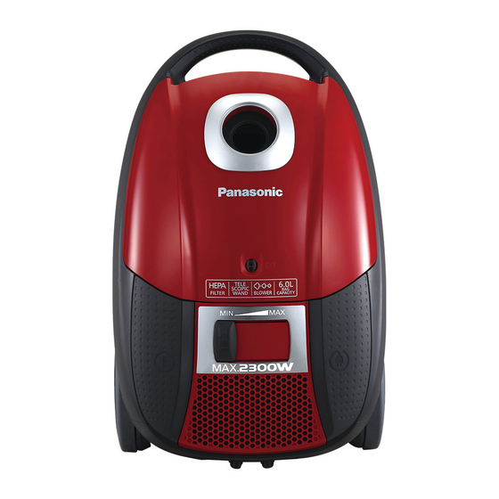
1 Specifications Model MC-CG711 Power Source 220V~240V~50/60Hz Input Power (Max) 1900W Input Power (IEC) 1500-1800W Power Control SLIDE Dust Capacity 6.0L Automatic Cord Rewind Vac Gauge Exhaust Filter ANTI-BACTERIA Extension Wands METAL TELESCOPIC WAND Blower Operation Floor Nozzle 2-STEP Dust Bag... -
Page 3: Wiring Connection Diagram
3 Wiring Connection Diagram... -
Page 4: Disassembly And Assembly Instruction
4 Disassembly and Assembly Instruction 4.1. Disassembly of Upper and Step 4 Pull out the Exhaust Cover. Lower Body Step 1 Open the Dust Cover. Step 2 Remove the Dust Bag. Step 5 Remove 3 screws from back side of the body. Step 3 Remove 4 screws from the front side and 2 screws from bottom side of the body. -
Page 5: Disassembly Of Motor Case Set
Step 7 Place the set as diagram shown and disconnect the 4.2. Disassembly of Motor Case Set Wire Terminal from switch at the Upper Body. Step 1 Release Rear Cover from Screw Holders. Step 2 Remove Rear Cover. Step 8 Remove the Upper Body from Lower Body. Step 3 Pull up the Motor Case Set from the Lower Body. -
Page 6: Disassembly Of Cord Reel Unit
4.3. Disassembly of Cord Reel Unit 4.4. Disassembly of Rail Base Unit Step 1 Release the pretension of the Cord Reel Unit slowly by Step 1 Remove 1 screw. holding on the Power Plug and pressing on the Brake Lever. Step 2 Remove the Cord Reel Unit from the Motor Case Set by Step 2 Release the Catch and pull upward. -
Page 7: Disassembly Of Fan Motor Unit
Disassembly of Fan Step 4 Lift up the Motor Case Unit 4.5. Motor Unit Step 1 Remove the Swivel Cap. Step 2 Remove 1 screw from top and 2 screws bottom Motor Case Set. Step 5 Disconnect the Wire Terminal and remove the Motor Set. -
Page 8: Disassembly Of P.c.b. Ass'y
Step 6 Remove the Noise Supprassor Unit and Motor Support Disassembly of P.C.B. 4.6. Rubbers. Ass’y Step 1 Disassemble the Volume by widening the Tab using Screwdriver. Step 2 Remove Volume Upward. Step 3 Release Tabs and remove P.C.B. Cover. To reassemble the unit, reverse the disassembly proce- dure above. -
Page 9: Trouble Shooting Chart
5 Trouble Shooting Chart... -
Page 11: Exploded View And Replacement Parts List
6 Exploded View and Replacement Parts List 6.1. Exploded View Plug C3 Plug E2... -
Page 12: Attachment Exploded View
6.2. Attachment Exploded View... -
Page 13: Packing Instruction
6.3. Packing Instruction EXTENSION WAND UNIT HOSE UNIT CURVED WAND FLOOR NOOZLE ASS'Y DUSTING BRUSH A CREVICE NOZZLE BODY INSTRUCTION BOOK CONNECTION PIPE... -
Page 14: Replacement Parts List
6.4. Replacement Parts List Safety Ref. No. Part No. Part Name & Description Remarks XTN4+20BFJ PAN TAP SCREW XTN4+10FFJ SCREW XTN4+14BFJ TAPPING SCREW XTN4+12BFJ PAN TAP SCREW YMV02ABW000 UPPER BODY YMV42KBW000 FILTER SUPPORTER YMV32KBW000 FILTER CASE YMV38KBZ000 EXHAUST FILTER YMV96LBW000 BLOWER OUTLET UNIT YMV93KBZ0R0 DUST COVER ASS'Y... - Page 15 MMH1109...
Need help?
Do you have a question about the MC-CG711 and is the answer not in the manual?
Questions and answers