Table of Contents
Advertisement
Quick Links
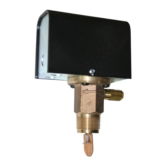
Series FS7-4
Industrial Liquid Flow Switch
(specified models only)
OPERATION
This control is an independently mounted water flow
sensing device that makes or breaks an electrical
circuit when flow stops or starts.
• Before using product, read and understand instructions.
• Save these instructions for future reference.
• All work must be performed by qualified personnel trained in the proper application,
installation, and maintenance of plumbing, steam and electrical equipment and/or systems in
accordance with all applicable codes and ordinances.
• To prevent electrical shock, turn off the electrical power before making electrical
connections.
• To prevent an electrical fire or equipment damage, electrical wiring insulation must have a
rating of 167˚F (75˚C) if the liquid's temperature exceeds 180˚F (82˚C).
• To prevent electrocution, when the electrical power is connected to the flow switch, do not
touch the terminals.
• Make sure flow switch electrical cover is secured before turning on electric power.
Failure to follow this warning could cause property damage, personal injury or death.
Installation & Maintenance
WARNING
McDonnell & Miller
Instructions
MM-607(B)
Series FS7-4
Series FS7-4E
Advertisement
Table of Contents

Related Manuals for ITT McDonnell & Miller FS7-4 Series


Summary of Contents for ITT McDonnell & Miller FS7-4 Series
- Page 1 McDonnell & Miller Installation & Maintenance Instructions MM-607(B) Series FS7-4 Industrial Liquid Flow Switch (specified models only) Series FS7-4 OPERATION This control is an independently mounted water flow sensing device that makes or breaks an electrical circuit when flow stops or starts. Series FS7-4E WARNING •...
-
Page 2: Specifications
SPECIFICATIONS Maximum Liquid Pressure: 300 psi (21 kg/cm ) (All models except “S”) 1000 psi (70 kg/cm ) (“S” models ) Liquid Temperature Range (T 32 - 300˚F (0 - 149˚C) (All models except “W”) -65 - 300˚F (-54 - 149˚C) (“W” models) Ambient Temperature Range (T 32 - 120˚F (0 - 49˚C)(All models except “W”) -65 - 300˚F (-54 - 149˚C) (“W”... -
Page 3: Flow Rates
FLOW RATES Flow rates required to activate flow switch are shown Settings will vary when used to sense flow of other in chart below. The values are calculated for sensing fluids. water (potable, non-polluted) in a horizontal pipe. Flow Rates NOTE: DO NOT USE LIQUID FLOW SWITCHES Mode of Operation Max. -
Page 4: Installation
INSTALLATION – STEP 1 - Paddle Sizing Pipe size determines the paddle length. Use the 1" chart below to choose the correct paddle size for your installation. (25mm) Pipe size Paddle To Use in. (mm) 1-1/4” (32) 1” Paddle 1-1/2” (40) 1”... - Page 5 STEP 2 - Determine the Location of the Flow Switch • The flow switch must be located in a horizontal section of pipe where there is a straight horizontal run of at least 5 pipe diameters on each side of the flow switch. •...
- Page 6 STEP 3 - Connecting the Flow Switch to Pipe a. Insert the 8/32 x 1/4” flathead screw through washer and paddle. Attach screw to opposite side of the paddle arm’s curve and tighten to a torque of approximately 12-16 lb•in (1.36-1.81 N•m). b.
-
Page 7: Step 4 - Electrical Installation
STEP 4 - Electrical Installation WARNING • To prevent electrical shock, turn off the electrical power before making electrical connections. • To prevent an electrical fire or equipment damage, electrical wiring insulation must have a rating of 167˚F (75˚C) if the liquid’s temperature exceeds 180˚F (82˚C). •... - Page 8 b. Electrical Conduit Connection • Connect electric conduit to flow switch electrical enclosure. • Follow accepted electrical practices when installing fittings and making connections. • Refer to and follow local codes and standards when selecting the types of electrical fittings and conduit to connect to flow switch.
- Page 9 b. Electrical Conduit Connection • Connect electric conduit to flow switch electrical enclosure. • Follow accepted electrical practices when installing fittings and making connections. • Refer to and follow local codes and standards when selecting the types of electrical fittings and conduit to connect to flow switch.
- Page 10 STEP 6 - Adjustment Adjustment is necessary only if required flow/no flow set- points are above factory set minimum. a. Unscrew housing cap (A) using a flathead screwdriver. HOUSING ADJUSTING SCREW b. Turn the adjusting screw (B) clockwise to “B” “A”...
-
Page 11: Troubleshooting
MAINTENANCE TROUBLESHOOTING SCHEDULE: Problem: 1. Flow Switch Does Not Operate • Inspect paddles annually. Turbulent or high flow velocity conditions may require more Solution: a. Make sure power has been turned on to device frequent inspection and/or replacement. and flow switch. b. - Page 12 ©2006 ITT Corporation Printed in U.S.A. 11-06 246618 8200 N. Austin Ave. Morton Grove, IL 60053 tel: 847-966-3700 fax: 847-966-9052 www.mcdonnellmiller.com...
Need help?
Do you have a question about the McDonnell & Miller FS7-4 Series and is the answer not in the manual?
Questions and answers