Table of Contents
Advertisement
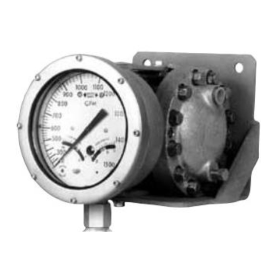
Model 581A-0
Contents
Safety ............................................................................................................ 2
Section 1-Introduction ................................................................................. 3
General ......................................................................................................... 3
Wiring ........................................................................................................ 5
Differential Pressure Unit .......................................................................... 5
............................................................................................... 6
General:..................................................................................................... 6
Section 2-Installation ................................................................................... 9
Mounting/Piping/DPU Installation ................................................................. 9
Electrical Connection .................................................................................... 9
Switch Use .................................................................................................... 9
Startup ........................................................................................................ 10
Switch Wiring .............................................................................................. 10
Section 3-Maintenance and Calibration ....................................................11
Tools.............................................................................................................11
Bezel/Lens Assembly or Cover Installation and Removal........................... 12
Pointer Installation and Removal ................................................................ 13
Pointer Installation .................................................................................. 13
Pointer Removal ...................................................................................... 14
Scale Plate Installation and Removal ......................................................... 14
Indicator Calibration .................................................................................... 15
Drive Arm Tightness Test ......................................................................... 17
Drive Arm Stop Adjustment ..................................................................... 17
Switch Calibration ..................................................................................... 17
Calibration Setup ..................................................................................... 18
Linkage Calibration Procedure ............................................................... 18
Changing Switch Set Point ........................................................................ 20
Best Practices for Set Points ................................................................... 20
Changing Set Point of an In-Service Instrument ..................................... 20
Changing Set Point of an Out-of-Service Instrument .............................. 21
Range Changes ...................................................................................... 22
www.ittcontrols.com
www.ittcontrols.com
BARTON
®
DIFFERENTIAL PRESSURE
............................................................................... 6
......................................................................... 7
.............................................................................. 7
................................................................................. 20
contact@ittcontrols.com
contact@ittcontrols.com
NUCLEAR MODEL 581A
User Manual
Part No. 9A-C10766, Rev. 01
SWITCH
October 2011
Advertisement
Table of Contents

Related Manuals for ITT BARTON 581A


Summary of Contents for ITT BARTON 581A
-
Page 1: Table Of Contents
BARTON NUCLEAR MODEL 581A ® DIFFERENTIAL PRESSURE SWITCH User Manual Part No. 9A-C10766, Rev. 01 October 2011 Model 581A-0 Contents Safety ......................2 Section 1—Introduction ................. 3 General ......................3 Wiring ......................5 Differential Pressure Unit ................5 ....................6 General:..................... -
Page 2: Section 1-Introduction
Model 581A Di erential Pressure Switch Section 1 Section 1—Introduction General The 581A Differential Pressure Switch actuates single or dual signal circuits nected to the process or vessel by tubing or piping. Changes in differential pressure (DP) at the DPU produce a mechanical output which moves a pointer and switch actuation controls. - Page 3 Section 1 Model 581A Di erential Pressure Switch Actuating Cam Left Switch Right Switch Plunger Screw Plunger Screw Right Switch Left Switch Lock Screw Lock Screw Drive Arm Pointer Stop Bracket Switch Adjust Linkage Movement Assembly Left Switch Switch Adjust Linkage Adjustment Assembly* Terminal Strip...
-
Page 4: Wiring
Model 581A Di erential Pressure Switch Section 1 Mid-point DP B O T H S W I T C HES RELAX ED C AM S W I T C H "A" S W I T C H "B " CLOSED OPEN SWITCH CONTACTS... -
Page 5: General
Section 1 Model 581A Di erential Pressure Switch General: Actuating Unit (DPU) ...... Model 199 DPU Dial Size ......... 6 inches (150 mm) Service Conditions (Normal)... 40°F (4.4°C) to +180°F (+57.2°C) @ <90% R.H. Switch Repeatability ....... ±1% of calibrated span Switch Set-point Range .... - Page 6 Model 581A Di erential Pressure Switch Section 1 cation testing, which found the devices suitable for functional service in a limited harsh environment. The service conditions associated with the limited • normal conditions of 104°F and 0 psig • Radiation exposure to 1 x 10 Rads (TID) •...
- Page 7 Section 1 Model 581A Di erential Pressure Switch www.ittcontrols.com contact@ittcontrols.com...
-
Page 8: Section 2-Installation
Model 581A Di erential Pressure Switch Section 2 Section 2—Installation The instrument should be inspected at time of unpacking to detect any dam- age that may have occurred during shipment. IMPORTANT: The DPU was checked for accuracy at the factory. Do not change any of the settings during examination or accuracy could be affected. -
Page 9: Startup
Section 2 Model 581A Di erential Pressure Switch Startup For startup procedures, warnings, and other information, refer to Appendix A. IMPORTANT: To ensure the unit calibration is within factory-set calibration tolerances, perform the Calibration Check procedure on page Switch Wiring IMPORTANT: Figure 2.1 shows switch contacts in the relaxed (shelf) condition, the low switch set to trip at a position below the pointer scale position, and the high switch set to trip at a position above the pointer scale position. -
Page 10: Section 3-Maintenance And Calibration
Model 581A Di erential Pressure Switch Section 3 Section 3—Maintenance and Calibration The following checks are recommended for preventive maintenance: • Periodically inspect the alarm switch mechanism to verify that all mount- ing screws are seated properly. • Inspect linkage for wear. •... -
Page 11: Tools
Section 3 Model 581A Di erential Pressure Switch Tools The following tools are recommended for general maintenance of the Model 581A differential pressure switch. Table 3.1—Tools Equipment Purpose Pointer Puller Pointer removal Small Screwdriver Calibration adjustment Medium Screwdriver Bezel removal and replacement 1/4"... -
Page 12: Pointer Installation And Removal
Model 581A Di erential Pressure Switch Section 3 Figure 3.2, page 13. Replace the bezel/lens assembly. Pointer "slipped" rotated on hub Hub held in place with 1/4" wrench Figure 3.2—"Slipping" pointer 3. To test for reverse travel, connect the pressure source to the low-pressure (LP) housing and vent the HP housing. -
Page 13: Pointer Removal
Section 3 Model 581A Di erential Pressure Switch perpendicular blows to avoid bending the shaft. 3. Check the calibration of the indicating switch over its entire range (refer Scale Plate Installation and Removal, page 14). If the indicating switch is correctly calibrated, secure the pointer to the movement shaft by tap- 4. -
Page 14: Indicator Calibration
Model 581A Di erential Pressure Switch Section 3 To remove the scale plate, move the pointer to the 12 o'clock position, remove the screws from the scale plate, and gently guide the scale plate halves from beneath the bottom mounting tab. Screws are located at 12, 3 and 9 o'clock positions and near the center of the plate which overlays a narrow bracket. - Page 15 Section 3 Model 581A Di erential Pressure Switch 6. Release pressure. Set the pointer to zero, by slipping the pointer on the hub, per Calibration Check, step 2, page Repeat steps 4 and 5, as necessary, to obtain the correct zero/full-scale. Apply 50% DP.
-
Page 16: Drive Arm Tightness Test
Model 581A Di erential Pressure Switch Section 3 Lightly tap the indicator to overcome friction. The pointer should accu- rately indicate each applied pressure. 11. Test the instrument repeatability by applying 0%, 50%, 0%, 50% of full- scale differential pressure. The indicator should accurately indicate each applied pressure. -
Page 17: Switch Calibration
Section 3 Model 581A Di erential Pressure Switch 4. Bend the zero drive arm stop against the drive arm. 5. Verify calibration as applicable. Switch Calibration Before performing a complete calibration of the switch, perform a calibration check (See Calibration Check, page 12). -
Page 18: Linkage Calibration Procedure
Model 581A Di erential Pressure Switch Section 3 Linkage Calibration Procedure The switch linkage should be calibrated whenever the Model 581A switch has been rebuilt. To calibrate the switch linkage, perform the following steps. Refer to Figure 3.7 as needed. 1. -
Page 19: Changing Switch Set Point
Section 3 Model 581A Di erential Pressure Switch the pressure system to stabilize. Then change the pressure by a small amount. The magnitude of the pressure change is determined by the desired accuracy of the test. Tighten the lock screw before testing the switch performance. -
Page 20: Changing Set Point Of An In-Service Instrument
Model 581A Di erential Pressure Switch Section 3 remove the scale plate and inspect the switch and the switch mechanism. The scale plate is split to allow for removal without pulling the pointer. Changing Set Point of an In-Service Instrument (Not Recommended for Use the following procedure to set a set point for an instrument that is in ser- vice, when calibration pressures cannot be applied. -
Page 21: Range Changes
Section 3 Model 581A Di erential Pressure Switch Example: Scale has range of 0-60 psid. Set point is 24 psid, with decreasing pressure, (24/60 x 10 = 4). 1. Move the index pointer (item C) for the low switch from division 0 to division 4 tick mark. - Page 22 Model 581A Di erential Pressure Switch Section 3 Range, page A-18, and Bellows Unit Assembly (BUA) Replacement, page A-22, details or contact the factory for assistance. Troubleshooting For switch troubleshooting tips, see Table 3.2 below. For information related to the DPU, see Appendix A. Table 3.2—Troubleshooting Problem Possible...
- Page 23 Section 3 Model 581A Di erential Pressure Switch Table 3.2—Troubleshooting Problem Possible Probable Cause Corrective Action Source Switch Process Transients or surges cause Add time delay gages or add time Drifts Changes switches to actuate prema- circuit (set point turely not repeat- Set point and/or deadband are Specify DP range as low as...
- Page 24 Model 581A Di erential Pressure Switch Section 4 Section 4—Assembly Drawing and Parts List LOCATE THE SCALE PLATE UNDER THE MOUNTING TAB WITHOUT A SCREW AT THE 6 O’CLOCK POSITION. Figure 4.1—Model 581A-0 indicating switch (shown with glass lens) www.ittcontrols.com contact@ittcontrols.com...
- Page 25 Section 4 Model 581A Di erential Pressure Switch Table 4.1 contains components for Model 581A-0 indicating switches and Model 581A-2 blind switches with internal indicator. For parts list informa- tion on Model 581A-2 blind switches without indicator, see Table 4.2, page A-16.
- Page 26 Model 581A Di erential Pressure Switch Section 4 Table 4.1—Parts List, Model 581A-0 Indicating Switch and Model 581A-2 Blind Switch with Internal Indicator Item Description Part No. Unit Bracket (Switch to DPU) 9A-C0197-1019C Header Assembly 9A-C0580-1018B Screw, Cap:10-32 (select one) Model 581A-0 (with glass lens), 1"...
- Page 27 Section 4 Model 581A Di erential Pressure Switch Figure 4.2—Model 581A-2 blind switch without indicator www.ittcontrols.com contact@ittcontrols.com...
- Page 28 Model 581A Di erential Pressure Switch Section 4 Table 4.2 contains components for Model 581A-2 blind switches without indicator. For parts list information on Model 581A-0 indicating switches and Model 581A-2 blind switches with internal indicator, see Table 4.1, page Table 4.2—Parts List, Model 581A-2 Blind Switch without Indicator Item Description...
- Page 29 Section 4 Model 581A Di erential Pressure Switch Table 4.2—Parts List, Model 581A-2 Blind Switch without Indicator Item Description Part No. Unit O-ring (Plug), EPT 9A-C0001-1051R Screw, Rd. Hd., Slotted, 6-32 x 3/16 Lg. 9A-C0117-0013J Bracket Spacer 9A-C0199-0003C Screw, Socket, Flat Hd., 3/8-16 x 1 Lg. 9A-C0240-0004J Screw, Hex Hd., 3/8-16 x 1 Lg.
- Page 30 Model 581A Di erential Pressure Switch Section 4 Table 4.3—Torque Requirements for Switch Assembly Fasteners (See Figures 4.1 and 4.2 for part Item Description Part No. Torque* Unit Screw, B.H., Slotted, 6-32 x 3/16 9A-C0117-0013J Tight Lg. (Model 581A-0 only) Screw, Hex Head, 3/8-16 x 3/4 Lg.
- Page 31 Section 4 Model 581A Di erential Pressure Switch www.ittcontrols.com contact@ittcontrols.com...
Need help?
Do you have a question about the BARTON 581A and is the answer not in the manual?
Questions and answers