Table of Contents
Advertisement
Quick Links
VX1 User's Guide
IMPORTANT NOTICE
LXE's VX1 is obsolete.
This electronic manual has been made available as a courtesy to LXE's VX1
customers. Please contact your LXE customer support representative for
assistance and mobile device replacement.
Copyright © 2006 by LXE Inc.
All Rights Reserved
E-EQ-VX1OGWW-K-ARC
Advertisement
Table of Contents

Related Manuals for LXE VX1

Summary of Contents for LXE VX1
- Page 1 VX1 User’s Guide IMPORTANT NOTICE LXE’s VX1 is obsolete. This electronic manual has been made available as a courtesy to LXE's VX1 customers. Please contact your LXE customer support representative for assistance and mobile device replacement. Copyright © 2006 by LXE Inc.
- Page 2 While reasonable efforts have been made in the preparation of this publication to assure its accuracy, LXE assumes no liability resulting from any errors or omissions in this publication, or from the use of the information contained herein. Further, LXE Incorporated, reserves the right to revise this publication and to make changes to it from time to time without any obligation to notify any person or organization of such revision or changes.
-
Page 3: Table Of Contents
The ABCD Keyboard .......................6 The QWERTY Keyboard ......................6 IBM 3270 Overlay .........................7 IBM 5250 Overlay .........................7 Key Maps..........................7 DOS Key Functions Not Available on the VX1...............8 Keyboard LEDs ........................9 CAPS LED ..........................9 Secondary Keys LED ......................10 Status LED ...........................11 Control Keys...........................12 PCMCIA Slots ...................... - Page 4 Table of Contents Step 2 - Connect VX1 To Back Mounting Bracket.............25 Step 3 - Attach VX1 In Bracket Assembly To Bottom Mounting Bracket......26 Connect Antenna ....................28 Vehicle Remote Antenna Mount ....................28 Connect Serial Barcode Scanner ................29 Connect Serial Printer or PC..................
- Page 5 Table of Contents HAPTER EGULATORY OTICES AND AFETY NFORMATION Approvals ........................ 60 NDEX E-EQ-VX1OGWW-K-ARC VX1 User’s Guide...
- Page 6 Figure 9 The Status LED ...........................11 Figure 10 The VX1 Display Controls ........................12 Figure 11 The VX1 PCMCIA Slots........................13 Figure 12 VX1 Bracket - Mounting Dimensions (Not To Scale) ..............20 Figure 13 Suggested Mounting Positions ......................20 Figure 14 Torque Measurements ........................21 Figure 15 Strain Relief Cable Clamp Locations ....................22...
-
Page 7: The Vx1 Vehicle Mount Computer
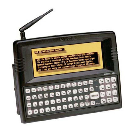
The VX1 Vehicle Mount Computer Introduction The VX1 Vehicle Mount Computer (VMT or VMC) is a rugged, vehicle-mounted, DOS based PC (Personal Computer) capable of wireless data communications from a fork-lift truck or any properly configured vehicle. The unit uses a PCMCIA radio (spread spectrum 900MHz or 2.4GHz) for wireless data communications. -
Page 8: Document Conventions
-22°F to 160°F (-30°C to 70°C) [non-condensing] Water, Sand Dust IEC IP56 Operating Humidity Up to 90% non-condensing at 104°F (40°C) Vibration Based on MIL Std 810D 15 kV Shock 75G, 5ms duration, 100 shock impacts VX1 User’s Guide E-EQ-VX1OGWW-K-ARC... -
Page 9: Quick Start
(e.g. antenna, external barcode scanner) and a power source. Use this guide as you would any other source book -- reading portions to learn about the VX1, and then referring to it when you need more information about a particular subject. This guide takes you through installation and operation of the LXE VX1. -
Page 10: Components
Components Components Antenna Connector PC Card Slots Speaker/Beeper CapsLock Indicator Indicator Status Indicator COM1/Scanner Connector COM2 Connector Power Connector 10 Fuse 11 Power Switch Figure 1 VX1 Components VX1 User’s Guide E-EQ-VX1OGWW-K-ARC... -
Page 11: The Half-Screen Display
Controls and Connectors Most external connectors for the VX1 are located on the bottom of the unit. COM 1 connects to a serial barcode scanner cable COM 2 connects to a serial printer or PC with the appropriate cables. -
Page 12: The Keyboards
The Keyboards The Keyboards The VX1 has an internal, custom keyboard in one of four versions: • QWERTY layout, with Standard overlay • QWERTY layout, with IBM 3270 overlay • QWERTY layout, with IBM 5250 overlay • ABCD layout with Standard overlay Each keyboard features a 60 key keyboard. -
Page 13: Ibm 3270 Overlay
In order to duplicate the codes sent when the alphanumeric key is pressed, the hidden keystroke must be used. The hidden keys supported by the VX1 are listed in the Appendix titled "Key Maps". The Key Maps appendix contains the key press sequences for the QWERTY keyboard and the ABCD keyboard. -
Page 14: Dos Key Functions Not Available On The Vx1
A function that is available at the DOS prompt on a desktop PC. Sys Req is for use in a multi-tasking environment to switch between various running applications. The VX1 is not a multi-tasking computer, nor is DOS in general considered a multi- tasking environment. -
Page 15: Keyboard Leds
When Caps-Lock is off, the LED is dark. Press 2 then <F1> to toggle Caps-Lock On and Off. Caps-Lock can also be set On or Off using CMOS Setup. Refer to the "VX1 Reference Guide." The default value of Caps-Lock is “Off”. E-EQ-VX1OGWW-K-ARC... -
Page 16: Secondary Keys Led
The Keyboards Secondary Keys LED The VX1 keyboard is equipped with several secondary keys. These keys are identified by the superscripted text found on the keyboard keys. The secondary keys are accessible by using two (2) keystrokes: the 2 key followed by the superscripted key. -
Page 17: Status Led
-- 2 key then <F3>. The status LED is green when the VX1 is in Suspend Mode. Suspend Mode is the lowest power- consumption state possible, while still retaining the system’s status. When the VX1 enters Suspend Mode, the display and keyboard backlight are turned off and the status LED stays green. -
Page 18: Control Keys
The Keyboards Control Keys The VX1 has several control keys. One key controls the keyboard backlight, a pair of keys controls the volume and another pair of keys controls the display brightness. The VX1 must be placed in Secondary Mode to access these functions. -
Page 19: Pcmcia Slots
PCMCIA Slots PCMCIA Slots The VX1 has one active PCMCIA slot – the right slot, slot 0. It supports the Personal Computer Memory Card International Association (PCMCIA) 2.1 standards. Slot 0 (the right slot, usually configured as Drive D:) accepts Type I, II or III PCMCIA SRAM cards. -
Page 20: Power Supply
Power Supply Power Supply Vehicle power input for the VX1 is 12V to 80V DC and is accepted without the need to perform any manual adjustments within the VX1. See the section titled “Installation”, sub-section titled “Vehicle 12-80VDC Direct Connection.”... -
Page 21: Getting Help
ServicePass website only. You can get help from LXE by calling the telephone numbers listed on the LXE Manuals CD, in the file titled “Contacting LXE”. This information is also available on the LXE website. -
Page 22: Accessories
8500 series tethered scanners. Refer to the manufacturers user guide for instruction. Note A: Adapter Kit Includes Hardware and Adapter Power Cord to mount a VX1/2 Computer utilizing the existing 1280 mounting bracket. Integrated keyboard bracket can not be used in conjunction with the adapter bracket. -
Page 23: Revision History
Supply Installation procedure, removed “The green wire is not used. Do not connect this wire. If the green wire has a bare end, use electrical tape (or otherwise insulated) to cover the bare end and ensure the bare wire does not contact anything.” The VX1 must be grounded when installed in a vehicle. - Page 24 Manuals and Accessories VX1 User’s Guide E-EQ-VX1OGWW-K-ARC...
-
Page 25: Installation
Before installation begins, verify you have the following vehicle mounting bracket assembly components: Components Back Mounting Bracket Assembly This bracket is attached to the VX1. It is pre- assembled at LXE. 6 each 8-32 x 7/16 Pan Head Screw (connects to the back of the computer) -
Page 26: Mounting Dimensions
0.18 in / 4.5 mm 0.88 in / 22.3 mm 1.25 in / 31.75 mm Figure 12 VX1 Bracket - Mounting Dimensions (Not To Scale) Mounting Positions Figure 13 Suggested Mounting Positions Viewing angle is 45° to both sides of the bottom mounting bracket. -
Page 27: Torque Measurements
You will need a torquing tool capable of torquing to 50 inch pounds (5.64±.56 N/m). Torque pan head screws to 16.0±1 in/lb (1.8±.11 N/m) when assembling the back mounting bracket to the VX1. Torque ¼ bolts to 50.0±5 in/lb (5.64±.56 N/m) when assembling the bottom mounting bracket to the back mounting bracket. -
Page 28: Cable Retention Assembly
Before beginning the vehicle mounting bracket assembly, attach the cable ties to the VX1 and the back mounting bracket as shown in the following figures. Use the cable ties to secure the power cable and RS-232 cables to the VX1 after it has been mounted to the vehicle. -
Page 29: Connect Cable Ties To Back Mounting Bracket
Figure 16 Cable Ties on Back Mounting Bracket Assembly Slide the pointed end of the cable tie through the top opening in the push mount. Snap the push mount through the top hole and toward the VX1 as shown in the above figure. -
Page 30: Procedure
Step 1 - Mount Bottom Mounting Bracket To Vehicle. Position the bracket to allow access to the switches and ports on the bottom of the VX1. Attach the bottom mounting bracket to the vehicle mounting surface using six 1/4 bolts (or equivalent) fasteners. -
Page 31: Step 2 - Connect Vx1 To Back Mounting Bracket
Turn the VX1 off before attaching it to the back mounting bracket. Place the VX1 face down on a stable surface. Position the back mounting bracket on the VX1, matching the screw holes in the bracket to the screw holes on the back of the VX1. -
Page 32: Step 3 - Attach Vx1 In Bracket Assembly To Bottom Mounting Bracket
Do not torque bolts until all bolts are in place and viewing angle is adjusted. Loosen the hex bolts on both sides to adjust the viewing angle of the mounted VX1. Torque the hex bolts to 50±5 in/lb (5.64±.56 N/m). -
Page 33: Figure 21 Vx1 In Vehicle Bracket
Install Mounting Brackets Figure 21 VX1 in Vehicle Bracket E-EQ-VX1OGWW-K-ARC VX1 User’s Guide... -
Page 34: Connect Antenna
Connect Antenna Connect Antenna Note: VX1’s equipped with a radio require an external antenna. See “Accessories”. A VX1 without a radio does not use an antenna. Antenna Base Antenna Pin 2.4GHz Antenna 900MHz Antenna Figure 22 Connect Antenna The antenna pin is the same for 900MHz and 2.4GHz spread spectrum radios. -
Page 35: Connect Serial Barcode Scanner
Use the strain relief cable clamps to secure the cable to the VX1. Turn the VX1 on. When you have finished using the scanner, remove it from the VX1 and store the scanner in a closed container or bag. E-EQ-VX1OGWW-K-ARC... -
Page 36: Figure 24 Vx1 With Generic Barcode Scanner Attached
Connect Serial Barcode Scanner Figure 24 VX1 with Generic Barcode Scanner Attached Good Scan LED (or equivalent) Trigger Laser Aperture at Front Figure 25 Generic Barcode Scanner Refer to the documentation received with the barcode scanner for setup and programming instructions. -
Page 37: Connect Serial Printer Or Pc
Refer to the documentation received with the printer or PC for setup, troubleshooting and maintenance instructions. The printer or PC cable requires a nine-pin D-shell female connector for the VX1. The printer or PC cable is attached to the connector marked “COM2”. -
Page 38: Connect Power Cable
Connect Power Cable Connect Power Cable Turn the VX1 off before attaching the power plug. Connect the power cable to vehicle power (See the following section titled “Vehicle 12- 80VDC Direct Connection.”) - or - to an AC adapter. (See the following section titled “External Power Supply.”). -
Page 39: External Power Supply, Optional
Plug cordset into appropriate, grounded, electrical supply receptacle (AC mains). Connect the 4 pin water tight connector end to the VX1’s Power Connector by aligning the connector pins to the power connector; push down on the water tight connector and twist it to fasten securely. -
Page 40: Vehicle 12-60Vdc Direct Connection
Correct electrical polarity is required for safe and proper installation. Connecting the cable to the computer with the polarity reversed will cause the computer’s fuse to be blown. See the following figure titled "Vehicle Connection Wiring Color Codes" for additional wire color-coding specifics. VX1 User’s Guide E-EQ-VX1OGWW-K-ARC... -
Page 41: Figure 31 12-60Vdc Vehicle Connection Wiring Color Codes
This computer accepts a wide DC input voltage range. Do not connect the input power cable to any other LXE computer or damage to that computer may occur. Provide mechanical support for the cable by securing it to the vehicle structure at approximately one foot intervals, taking care not to overtighten and pinch conductors or penetrate outer cable jacket. -
Page 42: Vehicle 12-80Vdc Direct Connection
Correct electrical polarity is required for safe and proper installation. Connecting the cable to the computer with the polarity reversed will cause the computer's fuse to be blown. See the following figure titled "Vehicle Connection Wiring Color Codes" for additional wire color-coding specifics. VX1 User’s Guide E-EQ-VX1OGWW-K-ARC... -
Page 43: Figure 34 12-80Vdc Vehicle Connection Wiring Color Codes
Note: This computer accepts a wide DC input voltage range. Do not connect the computer's input power cable to any other LXE computer or damage to that computer may occur. Provide mechanical support for the cable by securing it to the vehicle structure at approximately one foot intervals, taking care not to overtighten and pinch conductors or penetrate outer cable jacket. -
Page 44: Fuse Replacement For The Vx1
Fuse Replacement for the VX1 Fuse Replacement for the VX1 The VX1 uses a 125V, 5A time delay (slow blow), high current interrupting rating fuse that is externally accessible and user replaceable. Should it need replacement, replace with same size, rating and type of fuse -- Bussman Type GMC-5 (5x20mm). -
Page 45: Operation
The power (on/off) switch is a toggle switch located on the bottom of the VX1. The switch is sealed by a rubber boot seal. The Status LED or the display, located on the front of the VX1, is lit when the power is on. -
Page 46: Reset Key Sequence (Reboot)
When the system is rebooted, the current contents of RAM are lost. Save any needed data and exit in an orderly fashion from any running programs before rebooting. When the VX1 is turned on or rebooted, the following settings are restored from flash memory and are configured using CMOS Setup. -
Page 47: Cleaning The Glass Display/Scanner Aperture
Set Display Brightness First, press the 2 key to place the VX1 in Secondary Mode. The VX1 brightness keys control the electroluminescent display in the following way: Icon Description <F4> Pressing and holding this key increases the brightness of the display <F5>... -
Page 48: Keyboard Backlight Control Key
(Power Management may be configured so they both time out simultaneously.) First, press the 2 key to place the VX1 in Secondary Mode. Then press the <F10> or Backlight Control key. When the keyboard backlight is on, pressing the Backlight Control key sequence (2 and <F10>) -
Page 49: Panning The Display
Panning the Display Panning the Display The VX1 display can be panned up and down in order to view the entire virtual screen. Display panning can also be controlled by an application running on the VX1. When at the DOS prompt:... -
Page 50: Figure 38 Panning, Center Display Window
At this point, a pan up command moves the pointer to line 4. The next pan up command moves the pointer to line 1. A pan up command at line 1 does not wrap the display. VX1 User’s Guide E-EQ-VX1OGWW-K-ARC... -
Page 51: Power Status And The Status Led
Power Status and the Status LED The VX1 has a Status LED, located on the front of the unit, that is illuminated green when the unit is powered on. The Status LED and the display are dark when power is disconnected. -
Page 52: Video Timeout State
The Status LED turns off. • Sticky key settings and keypresses are cleared and ignored during Suspend. Powering the VX1 off when it is in the suspend state causes all unsaved work to be discarded e.g. TE forms, barcode reads, etc. VX1 User’s Guide... -
Page 53: Critical Suspend State
When the unit is in the Critical Suspend state the Status LED blinks green, all peripherals are shut down, the CPU clock is stopped, power is removed from the PCMCIA card(s) and the VX1 may beep. The VX1 is saving the state prior to shut down and cannot be used. -
Page 54: Laser Barcode Scanner Warnings
Figure 41 Caution Labels Figure 42 Caution Labels Class II Scanner Class IIIA Scanner Do not pour, spray, or spill any liquid on the scanner. The Barcode Scanner contains the circuitry, scanning motor and laser. Handle with appropriate care. VX1 User’s Guide E-EQ-VX1OGWW-K-ARC... -
Page 55: Enter Data
The keyboard is used to manually input data that is not collected otherwise. Almost any function that a full sized computer keyboard can provide is duplicated on the VX1 keyboard but it may take a few more keystrokes to accomplish a keyed task. -
Page 56: Distance From Label
Keep fingers and rough or sharp objects away from the scan aperture. Wipe the scanner window periodically with a damp, soft cloth. Remove lint or foreign material with clean, filtered canned air. Do not scrub optical surfaces, clean only those areas which are soiled. VX1 User’s Guide E-EQ-VX1OGWW-K-ARC... -
Page 57: Chapter 1 Key Maps
Figure 44 QWERTY Keypad and ABCD Keypad The key maps that follow represent the commands used when running LXE’s ANSI Plus (with either 900MHz or 2.4GHz radios) or LDS Plus (with 900MHz radios) Terminal Emulation (TE) programs. When running these... -
Page 58: Key Map 101-Key Equivalencies
Up Arrow Down Arrow Down Arrow Right Arrow Right Arrow Left Arrow Left Arrow Insert Ins/BkSp Delete (numeric) Home Left Arrow The Contrast Adjustment keys have no function because the VX1 is equipped with an Electroluminescent display. VX1 User’s Guide E-EQ-VX1OGWW-K-ARC... - Page 59 Key Map 101-Key Equivalencies Press These Keys and Then To get this Press this Shift Ctrl CapsLock Right Arrow Page Up Up Arrow Page Down Down Arrow Right Shift Right Alt Right Ctrl ScrollLock E-EQ-VX1OGWW-K-ARC VX1 User’s Guide...
- Page 60 Key Map 101-Key Equivalencies Press These Keys and Then To get this Press this Shift Ctrl CapsLock 1 (alpha) 2 (alpha) 3 (alpha) 4 (alpha) 5 (alpha) 6 (alpha) 7 (alpha) 8 (alpha) 9 (alpha) VX1 User’s Guide E-EQ-VX1OGWW-K-ARC...
- Page 61 9 (numeric) 0 (numeric) DOT (numeric) < > / (numeric) / (alpha) - (numeric) - (alpha) + (numeric) + (alpha) * (numeric) * (alpha) : (colon) ; (semicolon) _ (underscore) , (comma) ‘ (apostrophe) ~ (tilde) “ E-EQ-VX1OGWW-K-ARC VX1 User’s Guide...
- Page 62 Key Map 101-Key Equivalencies Press These Keys and Then To get this Press this Shift Ctrl CapsLock & VX1 User’s Guide E-EQ-VX1OGWW-K-ARC...
-
Page 63: Ibm 3270 And Tn3270 Terminal Emulator Keypad
Figure 46 IBM 5250 Specific Keypad This keypad is designed to allow the user to enter terminal emulator commands when running LXE’s IBM 5250 and TN5250 Terminal Emulation (TE) programs. When running these programs please refer to the following terminal emulation reference guides for equivalent keys and keypress sequences: •... - Page 64 Key Map 101-Key Equivalencies VX1 User’s Guide E-EQ-VX1OGWW-K-ARC...
- Page 65 Operation of this equipment in a residential area is likely to cause harmful interference in which case the user will be required to correct the interference at his own expense. Warning: Changes or modifications to this device not expressly approved by LXE, Inc., could void the user’s authority to operate this equipment.
- Page 66 Information to User A label on the exterior of the device should resemble one of the labels shown below (the label contains the LXE part number of the installed radio card). The labels shown below and affixed to the device, identify where the device may be used and where its use is restricted.
- Page 67 Safety of information technology equipment, including electrical business + Amendments equipment A1..A4 We, LXE Inc., declare that the equipment specified above complies with all Essential Health and Safety Requirements of the above Directives and Standards, as amended. Place: LXE Inc., Norcross GA USA...
- Page 68 Safety of information technology equipment, including electrical business equipment + Amendments A1..A4 We, LXE Inc., declare that the equipment specified above complies with all Essential Health and Safety Requirements of the above Directives and Standards, as amended. Signed: Place: LXE Inc., Norcross GA USA R.
- Page 69 Safety of information technology equipment, including electrical business + Amendments equipment A1..A4 We, LXE Inc., declare that the equipment specified above complies with all Essential Health and Safety Requirements of the above Directives and Standards, as amended. Place: LXE Inc., Norcross GA USA...
- Page 70 EN 60950-2: 1992 + A1..A4 Safety of information technology equipment, including electrical business equipment We, LXE Inc., declare that the equipment specified above complies with all Essential Health and Safety Requirements of the above Directives and Standards, as amended. Place LXE Inc., Norcross GA USA...
- Page 71 With regard to the use of external antennas The LXE 6726 can be equipped with external antennas. The antennas listed have been evaluated with the LXE 6726 pursuant to ETSI EN 300 328, and therefore meet the definition of ‘dedicated antenna’ per ERC/REC 70-03 Appendix 1 Table 3; thus the requirement set forth in ERC/REC 70-03 , Annex 3 are met by the LXE model 6726 transceiver.
- Page 72 EN60950-1: 2001 business equipment The product carries the CE Mark: We, LXE Inc., declare that the equipment specified above complies with all Essential Health and Safety Requirements of the above Directives and Standards, as amended. Date of issue: June 18, 2003 Cyril A.
- Page 73 With regard to the use of external antennas The LXE 6816 can be equipped with external antennas. The antennas listed have been assessed with the LXE 6816 pursuant to EN 300 328, and therefore meet the definition of ‘dedicated antenna’. The table below lists the maximum output power setting for the radio module in order to result in a total EIRP of 100mW or less.
- Page 74 Regulatory Notices and Safety information A/C Power Supply Safety Statement – VX1 Output Rated 12 – 80 VDC, 3.5 A. Optional A/C Power Supply: Outside North America, this unit is intended for use with an IEC certified ITE power supply with output rated as stated at the top of this page.
- Page 75 Danish – DK; English – US; Finnish – FI; French- - FR; German – DE; Greek – GR; Italian – IT; Norwegian – NO; Portuguese – PT; Spanish – ES; Swedish – SE; Turkish – TR. Updated 10/01/2001 E-EQ-VX1OGWW-K-ARC VX1 User’s Guide...
- Page 76 Regulatory Notices and Safety information VX1 User’s Guide E-EQ-VX1OGWW-K-ARC...
- Page 77 CPU ................1 Connector, Location..........4 Critical Suspend substitution of unauthorized........28 what happens when ..........47 Critical Suspend state ..........47 Back Mounting Bracket and VX1............22, 25 Data entry, How To ..........49 Backlight Control Keys ...........12 Defaults Backup Battery ............14 Caps Lock .............9 Barcode Scanner............29 CMOS Settings ...........40...
- Page 78 Optional Power Supply ........33 for printer or PC..........31 Power Cable ............32 Normal Power Mode ..........45 Printer or PC ............31 NUM LOCK Scanner..............29 and 2 Functions ..........7 Disabled ..............7 Key Map Chart ............52 Key Map, 3270 ............51 On/Off Switch ............39 VX1 User’s Guide E-EQ-VX1OGWW-K-ARC...
- Page 79 QWERTY keypad ...........51 Trigger ..............30 QWERTY layout ............6 Unavailable Radio Cards and TEs ..........13 DOS key functions..........8 Rebooting the VX1..........40 Universal Input Power Supply.........14 Reset ................40 Unsuccessful Scan indicators ........50 Resume/Suspend Mode Items turned on ...........11 Vehicle Mount Footprint .........20 Vehicle Mounting Bracket, Installation Procedure .19...
- Page 80 Index VX1 User’s Guide E-EQ-VX1OGWW-K-ARC...
Need help?
Do you have a question about the VX1 and is the answer not in the manual?
Questions and answers