Table of Contents
Advertisement
Quick Links
UM2517
User manual
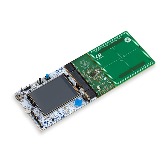
ST25R3916-DISCO and STEVAL-25R3916B
reference graphical user interface
Introduction
The ST25R3916-DISCO GUI (STSW-ST25R010) software allows the user to configure,
evaluate, and communicate with the ST25R3916-DISCO and STEVAL-253916B kits using a
PC.
The software must be used with the ST25R3916-DISCO or the STEVAL-253916B kits,
which include a ready-to-use board to interface with the host PC through USB. This
software allows the user to evaluate the features of ST25R3916 and ST253916B, high
performance NFC universal device and EMVCo readers, communicating with the 32-bit
core STM32L476 MCU via the SPI bus.
The boards are powered through the USB port, and no external power supply is required.
They include an ST25R3916 or an ST25R3916B device, an etched antenna, and the
associated tuning components.
This software package includes the ST25PC-NFC software, which allows access to all
features of ST25 NFC / RFID Tags and ST25 Dynamic NFC Tags.
March 2023
UM2517 Rev 3
1/40
www.st.com
1
Advertisement
Table of Contents

Related Manuals for ST ST25R3916-DISCO


Summary of Contents for ST ST25R3916-DISCO
- Page 1 The ST25R3916-DISCO GUI (STSW-ST25R010) software allows the user to configure, evaluate, and communicate with the ST25R3916-DISCO and STEVAL-253916B kits using a The software must be used with the ST25R3916-DISCO or the STEVAL-253916B kits, which include a ready-to-use board to interface with the host PC through USB. This...
-
Page 2: Table Of Contents
Method 2: ST-Link ........ - Page 3 UM2517 List of figures List of figures Figure 1. Device manager window........... . 5 Figure 2.
-
Page 4: Demonstration Kits
1.3.1 Method 1: DFU of STM32L4 The ST25R3916-DISCO demonstration kit contains a DFU driver, to install before going through a firmware update. Typically, the driver is installed in background. If this fails, open the GUI, select “Firmware update” and follow the procedure detailed below. -
Page 5: Figure 1. Device Manager Window
\Driver” and install it Under “Universal Serial Bus controllers” appears “STM device in DFU Mode” (Figure In the meantime, the ST25R3916-DISCO GUI is in timeout, and the USB field in the status bar is red To do the update, restart from point Caution: The loading of a wrong firmware makes the board unusable. -
Page 6: Method 2: St-Link
Demonstration kits UM2517 Figure 2. Device detected 1.3.2 Method 2: ST-Link Use the ST-Link integrated on MB1396. Connect the mini USB to your PC and simply drag and drop the firmware binary to the new appearing drive. 6/40 UM2517 Rev 3... -
Page 7: St25R3916 Discovery Gui Tab
ST25R3916 Discovery GUI tab If the software package is installed correctly, the demonstration is put into USB mode (User button while starting), the ST25R3916-DISCO board is connected via micro USB to PC USB port, and the main menu is displayed (see Figure The toolbar also contains the ST25PC-NFC icon, which enables the ST25 tags editing. -
Page 8: Startup Tab
Demonstration kits UM2517 1.4.1 StartUp tab Figure 3. StartUp tab The status tab on the bottom right corner shows the connection status. If the HW is successfully connected via USB the status turns to green, and displays the firmware version. •... -
Page 9: Antenna Features Tab
UM2517 Demonstration kits 1.4.2 Antenna features tab Figure 4. Antenna features tab • The needle shows the amplitude as measured on RFI, and the phase difference between RFI and RFO. • The antenna can be tuned for a target amplitude or a target phase, or for a combination of these parameters. -
Page 10: Wakeup Tab
Demonstration kits UM2517 1.4.3 Wakeup tab The devices offer different wake-up modes. Each one generates an interrupt to the microcontroller in sleep mode: Inductive (amplitude) Inductive (phase) Capacitive (not available on ST25R3916B) Note: This demonstrator is for evaluation purposes. There are continuous updates ongoing, which may result in extra current consumption. -
Page 11: Figure 6. Wakeup Window - Inductive (Phase) Wake-Up Enabled
UM2517 Demonstration kits Figure 6. Wakeup window - Inductive (phase) wake-up enabled Note: Different wake-up ranges can be achieved with the phase or amplitude method, depending upon the antenna matching network. Capacitive wake-up This method (not available on ST25R3916B) allows the user to measure the capacitance across two electrodes. -
Page 12: Figure 7. Wakeup Window - Capacitive Wake-Up Enabled
Demonstration kits UM2517 Figure 7. Wakeup window - Capacitive wake-up enabled Additional parameters are: • Delta (window size) defines the window in which no interrupt is generated. If the actual measured value is within the window range, no interrupt is generated. •... -
Page 13: Dpo
UM2517 Demonstration kits 1.4.4 DPO stands for dynamic power output. It is a software-based feature for the dynamic control of the transmitter driver resistance and the generated RF field, depending upon the presence of a PICC. A dynamic RF power adjustment can be useful in challenging environments where strong antenna detuning causes an abrupt increase in driver current and a violation of the maximum allowed field strength in the applicable standard. -
Page 14: Figure 9. Dpo Panel Enabled
Demonstration kits UM2517 Figure 9. DPO panel enabled DPO measurement methods The two drop-down fields at the top of the DPO screen allow the user to configure the number of power levels and the source of measurement to be used to adjust the RF power. One of the two measurement methods (amplitude or phase) can be chosen. -
Page 15: Figure 10. Setting Dpo With Amplitude Based Measurement, Using Two Power Levels
UM2517 Demonstration kits Figure 10. Setting DPO with amplitude based measurement, using two power levels To use the DPO and to find the correct threshold levels, press the “Continuous measure” button. The device emits a continuous carrier using the selected RFO resistance, and displays the measurement result and DPO status in the GUI. -
Page 16: Figure 12. Switching Resistance Values
Demonstration kits UM2517 Figure 12 shows an example of how the threshold levels can be set to switch between two resistance values. Figure 12. Switching resistance values In most cases, the user must reduce the generated field in close proximity of the reader. This means that sliders or threshold levels must be moved down into the region of interest. -
Page 17: Figure 14. Analog Configuration With Dpo Modes
UM2517 Demonstration kits As a result, the user finds the following new modes controlling AWS: • DPO_A_106_Level0 • DPO_A_106_Level1 • DPO_A_106_Level2 • DPO_A_106_Level3 • DPO_B_106_Level0 • DPO_B_106_Level1 • DPO_B_106_Level2 • DPO_B_106_Level3 They contain functions with register settings for mode A and B, with distinct parameters, up to four power levels. -
Page 18: Figure 15. Dpo Tab
Demonstration kits UM2517 Figure 15. DPO tab Figure 16. DPO log window The user can access a given set of power level parameters by clicking on the matching power level bar. The set of registers and the wave shape background color are updated accordingly. -
Page 19: Figure 18. Dpo Using Am Tooltip
UM2517 Demonstration kits Some tool tips are available as reminder, see Figure Figure 18. DPO using AM tooltip The AWS settings are shared with the analog configuration tab. They are updated when switching back to the analog configuration tab. The log window shows: Export DPO registers to Analog Config tab: Successfully exported: DPO_A_106_LEVEL0, DPO_A_106_LEVEL1, DPO_A_106_LEVEL2, DPO_A_106_LEVEL3, DPO_B_106_LEVEL0,... -
Page 20: Polling Tab
Demonstration kits UM2517 1.4.5 Polling tab Figure 19 shows the anticollision and multiprotocol features of the kits. Figure 19. Polling tab In addition to the protocols shown, the following protocols are supported: • Kovio barcode 128/256 bit (ISO 14443A checkbox) •... -
Page 21: Nfcip Tab
UM2517 Demonstration kits 1.4.6 NFCIP tab Figure 20 shows the NFCIP tab, which displays the peer-to-peer functionality. Figure 20. NFCIP tab Note: This feature requires an NFC enabled device supporting peer to peer protocol. The devices are initially configured to cycle through the initiator and target mode. The default setting for the bit-rate is 424 kbps. -
Page 22: Iso 14443A Tab
Demonstration kits UM2517 1.4.7 ISO 14443A tab Figure 21. ISO 14443A tab The “Configuration” button prepares the board for ISO 14443-A communication, and the following sequence activates the cards: • “REQA → Active” or “WUPA → Active” starts the anticollision procedure •... -
Page 23: Iso 14443B Tab
UM2517 Demonstration kits 1.4.8 ISO 14443B tab Figure 22. ISO 14443B tab The “Configuration” button prepares the board for ISO 14443-B communication, and the following sequence activates the card: • Click on “REQB” or “WUPB” button to poll once. The PUPI of a found tag is displayed. •... -
Page 24: Iso-Dep Tab
Demonstration kits UM2517 1.4.9 ISO-DEP tab The ISO-DEP tab is on a layer higher than ISO14443A and ISO14443B tabs. It automatically performs all activation steps after pressing Discover, and lets the user send APDUs according ISO7816-4 to contactless smartcards. Some frequently used APDUs can be pre-selected in the combobox. Figure 23. -
Page 25: Iso 15693 Tab
UM2517 Demonstration kits 1.4.10 ISO 15693 tab Figure 24. ISO 15693 tab The “Configuration” button prepares the board for ISO 15693 communication, and the following sequence activates multiple cards: • Click on “Configuration” button. • Set the ISO 15693 parameter to receive data rate, and the number of slots, which are used in the anticollision loop in the firmware. -
Page 26: Felica™ Tab
Demonstration kits UM2517 1.4.11 FeliCa™ tab Figure 25. FeliCa™ tab The “Configuration” button prepares the board for FeliCa communication, and the following sequence activates a card: • Set the number of slots used in the anticollision. • Click on “Poll” button to poll once for FeliCa cards. •... -
Page 27: Card Emulation Tag
UM2517 Demonstration kits 1.4.12 Card Emulation tag This tab allows the user to configure the ST25R3916 and ST25R3916B in card emulation. It either emulates a T4T (in case of NFC A), or a T3T (in case of NFC F). Different contents can be configured. -
Page 28: Nfc Type 1 Tab
Demonstration kits UM2517 1.4.13 NFC Type 1 tab Figure 27. NFC Type 1 tab The “Configuration” button prepares the board for NFC Type 1 communication, and the following sequence activates a card: • Click on “Select” button to send a WUPA •... -
Page 29: Nfc Type 2 Tab
UM2517 Demonstration kits 1.4.14 NFC Type 2 tab Figure 28. NFC Type 2 tab UM2517 Rev 3 29/40... -
Page 30: Debug Tab
Demonstration kits UM2517 The “Configuration” button prepares the board for ISO 14443A communication and enables the field. • Read data from page sequence: – Click on “Configuration” button – Click on “WUPA → Active” to find a card – Activate the “READ Data from Page” flag –... -
Page 31: Figure 29. Debug Tab
UM2517 Demonstration kits Figure 29. Debug tab Note: The usage of this tab is for experienced users only. UM2517 Rev 3 31/40... -
Page 32: Analog Config Tab
Demonstration kits UM2517 1.4.16 Analog Config tab This tab holds important configuration settings, required for setting chip specific registers for different technologies and bitrates. The concept of the analog configuration is part of the RFAL software structure and is used throughout different chip and board variants. •... -
Page 33: Figure 31. Functions Panel
UM2517 Demonstration kits The “CHIP_INIT” mode is used to set global registers that have to be used independently of other selected modes. As an example, the enable of pull-downs of SPI lines can be performed. Functions The functions window holds register values linked to modes. A function is composed of a name, the corresponding register, a mask, and the required value for the register. - Page 34 Demonstration kits UM2517 The “Save to file” button saves the current configuration in the analog configuration tab to the filesystem. The button “Generate code template” can be used to automatically generate a C header file for direct inclusion into a compiled firmware image. 34/40 UM2517 Rev 3...
-
Page 35: Register Map
UM2517 Register map Register map Pressing the “Register Map” button in the toolbar opens a dialog to interact with the ST25R3916 and ST25R3916B registers (Figure 32). Figure 32. Register map toolbar The GUI includes a register map window (Figure 33) showing the ST25R3916 registers. This window can be opened by clicking the “Register Map”... -
Page 36: Figure 33. Register Map
Register map UM2517 Figure 33. Register map 36/40 UM2517 Rev 3... -
Page 37: Logging
UM2517 Logging Logging The output can be observed using the log output panel, which can also be dragged out, to become its own window. Figure 34. Log window UM2517 Rev 3 37/40... -
Page 38: Using The St25Pc Nfc Application
Discovery GUI gets disconnected/inactive. By pressing the “Reader app” or closing the ST25PC-NFC the user can go back to Discovery operation. Figure 35. Register map toolbar More information on this GUI can be found in UM2444 “Software toolbox for NFC tags”, available on www.st.com. 38/40 UM2517 Rev 3... -
Page 39: Revision History
UM2517 Revision history Revision history Table 1. Document revision history Date Revision Changes 20-Dec-2018 Initial release. Changed document classification, from ST restricted to Public. Updated Section 1.4.2: Antenna features tab, Section 1.4.3: Wakeup Section 1.4.4: DPO. 08-Feb-2019 Updated Figure 3: StartUp... - Page 40 ST products and/or to this document at any time without notice. Purchasers should obtain the latest relevant information on ST products before placing orders. ST products are sold pursuant to ST’s terms and conditions of sale in place at the time of order acknowledgment.
Need help?
Do you have a question about the ST25R3916-DISCO and is the answer not in the manual?
Questions and answers