Table of Contents
Advertisement
Quick Links
Features
■
High bandwidth connection to host computer
– Networked 10/100 Mbit Ethernet
connection
– Local USB 1.1 or 2.0 Type B connection
■
VHDCI LVDS connection to target JTAG
interface - includes an STMC I/O convertor
Type A for target boards with a TTL JTAG
connector, an STMC I/O convertor Type C for
target boards with an ARM 20-way connector
or an STMC I/O convertor Type H for target
boards with a MIPI-34 connector
■
Connects to target RS-232 port for data relay
■
Supports STMicroelectronics single and
multi-core system-on-chip (SoC) devices
■
Provides system startup, program download,
debug and I/O services.
■
Enables concurrent debug of multiple cores in
multi-core SoCs
■
Built-in DHCP support
■
LCD and software support package for
configuration and administration
■
Support for Windows XP, Windows 7 and
Red Hat Linux hosts
■
ST Micro Connection Package
December 2011
Arrow.com.
Downloaded from
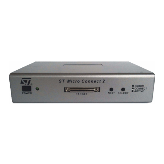
ST Micro Connect 2 host-target interface
Description
The ST Micro Connect 2 (STMC2) can be
connected to a local host or LAN using the
10/100 Mbit Ethernet connection or to a local PC
host using the USB 2.0 connection (USB 1.1
compatible). It connects to a target board's JTAG
connector and provides host software with the
ability to start up the target board, download
programs and debug them in the target.
For multi-core system-on-chip devices (SoCs) the
ST Micro Connect 2 can support multiple
concurrent debuggers, each connecting to a
different core on the chip.
The target is connected using a VHDCI LVDS
connection. A Type A, Type C or Type H I/O
convertor is included for target boards without an
on-board LVDS connector (the convertor supplied
is dependant on order code).
The ST Micro Connection Package provides
software utilities and firmware, including
TargetPacks for certain ST evaluation boards.
Supported hosts are Windows XP, Windows 7
and Red Hat Linux. The ST Micro Connect 2 is
compatible with a range of ST cores, SoCs and
toolsets: ST20, ST40, ST200, STxP70 and
specific ARM based products (including
Cortex-A9).
7912386 Rev 12
STMC2
1/58
www.st.com
1
Advertisement
Table of Contents

Related Manuals for ST STMC2


Summary of Contents for ST STMC2
- Page 1 TargetPacks for certain ST evaluation boards. Supported hosts are Windows XP, Windows 7 ■ LCD and software support package for and Red Hat Linux. The ST Micro Connect 2 is configuration and administration compatible with a range of ST cores, SoCs and ■...
-
Page 2: Table Of Contents
ST Micro Connect 2 power up ....... . . 11... - Page 3 Display ST Micro Connect 2 log file (--show-log) ....29 5.16 ST Micro Connect 2 status reports (--status) ..... . 30 5.17 Display version information (--version) .
- Page 4 Appendix B Target interface ......... 40 Connection to ST’s validation boards ......40 Connection using an STMC I/O convertor.
- Page 5 ST Micro Connect 2 Contents Disposal of this equipment at end-of-life ......50 F.3.1 Countries in the European Union (EU) ......50 F.3.2...
-
Page 6: Introduction
The ST Micro Connect 2 provides support for multiple debug-links multiplexed onto a single JTAG line. For multiple core debug, a single ST Micro Connect 2 replaces the need for multiple ST Micro Connect 1s used in conjunction with an ST-Multicore/MUX module. - Page 7 Using the ST Micro Connect 2 in this mode enables the target system to be remote and to be easily shared among users. This datasheet assumes that the user is reasonably familiar with the concepts and terms involved with TCP/IP networking.
-
Page 8: St Micro Connection Package
An RS-232 serial port connector is provided for connection to the target. This enables serial data to be relayed between the target and the host through the ST Micro Connect 2. A terminal emulation program can be run on the host to receive serial data and for the user to enter serial data, see Section 5.14: Configure serial redirect (--serial-relay) on page 27... -
Page 9: Administrator Privilege
1.1.3 Environment variables A number of environment variables should be set on the host, in order for the ST Micro Connection Package to function correctly. The installer and the DISPLAY environment variable On Linux hosts, set the DISPLAY environment variable to specify the X server being used, otherwise the installer will fail. - Page 10 Click on OK. In the Regional and Language Options/Region and Language window, click on PATH environment variable For all platforms include the full path to the bin directory of the ST Micro Connection Package in the PATH environment variable. Note: On Windows, the ST Micro Connection Package installer sets up the PATH, unless this option is de-selected.
-
Page 11: System Interface
The PWR LED illuminates when power is applied and the LEDs on the ST Micro Connect 2 front panel are illuminated in the following order: ACTIVE, CONNECT, ERROR. The LEDs then cycle for a few seconds to indicate that the ST Micro Connect 2 software is running. For a description of the status LEDs, see... -
Page 12: Terminology
ST Micro Connect 2 and the ST Micro Connect Lite, the original product is now known as the ST Micro Connect 1 and the generic term ST Micro Connect refers to the family of ST Micro Connect devices. In some instances these names are abbreviated to... -
Page 13: Lcd Interface
ST Micro Connect 2 LCD interface LCD interface The ST Micro Connect 2 has a sixteen character by two line LCD that is used to display status information and to configure the ST Micro Connect 2. The LCD has two modes of display: ●... -
Page 14: Configuration Menu
Press the Select button when the cursor is flashing over Yes, to execute the action and reboot the ST Micro Connect 2. If the cursor is over No when Select is pressed, the action is aborted and LCD menu is displayed. -
Page 15: Usb Connection
Chapter 2 on page If you wish to connect more than one ST Micro Connect 2 to the same host using USB, then each ST Micro Connect 2 must have a separate subnet. The simplest way to achieve this is to increment the third octet in the IP address. -
Page 16: Connection To The Host
Connect the ST Micro Connect 2 USB Type B connector to the Host USB type A connector using the supplied cable. Connect the ST Micro Connect 2 to the power supply and switch the power on at the ST Micro Connect 2 front panel. -
Page 17: Host Ip Address Assignment - Usb 1.1
Note: Ensure the Network Manager on the Linux host is enabled. It may take up to a minute for Linux to detect the presence of the ST Micro Connect 2 after it is plugged into the USB interface. Test the connection To test the connection, from the command line, enter the following command: stmcconfig --ip <ip address>... -
Page 18: Ethernet Connection
The use of the default IP address is not recommended for Ethernet installation. When there is the possibility of a network conflict then the ST Micro Connect 2’s IP address should be changed using the LCD interface as described in Section 4.2... -
Page 19: Configuring St Micro Connect 2 With Dhcp Network Configuration
IP address, but this is not guaranteed. Therefore you should confirm the IP address of your ST Micro Connect 2 on each reboot, either by looking at the LCD or running stmcconfig with the --identify option (see Section 5.6 on page... -
Page 20: Connection To Ethernet
Ethernet connection ST Micro Connect 2 Connection to Ethernet Connect the ST Micro Connect 2 to the Ethernet network, using the supplied CAT 5 UTP Ethernet cable. Testing Ethernet configuration When the ST Micro Connect 2 is configured and connected on the network by Ethernet, it should be visible on the network. -
Page 21: Configuration Using The Stmcconfig Utility
Some of these commands require a good understanding of networking principles. To pass commands to an ST Micro Connect 2, stmcconfig uses the ST Micro Connect 2’s IP address as identification. For a variety of reasons this IP address may not be known. -
Page 22: Automatic Network Configuration (--Dhcp)
Section 5.3 describes Flash partition organization. The option --firmware-downgrade switches the Flash partition, from which the ST Micro Connect 2 boots. This is useful if the previous firmware needs to be restored. User configuration settings for network interfaces are reset to the settings selected for the previous firmware installation. The command causes the ST Micro Connect 2 to reset and boot from the alternate firmware partition. -
Page 23: Upgrade Firmware In Flash (--Firmware-Upgrade)
The ST Micro Connect 2 firmware is held in Flash. Two copies of the firmware can be resident in Flash at any one time. When the ST Micro Connect 2 boots, it loads from the “current” firmware partition. The other firmware partition is known as the “alternate” firmware partition. -
Page 24: Identify An St Micro Connect 2 On A Network (--Identify)
The --identify option returns the IP addresses that are assigned to an ST Micro Connect 2 for both the Ethernet and USB-B interfaces. It uses the MAC address of the ST Micro Connect 2’s Ethernet port that is printed on the side of the ST Micro Connect 2. Note: The identify operation only discovers ST Micro Connect 2s on the local network. -
Page 25: Configure An St Micro Connect 2 Network Interface
Configure an ST Micro Connect 2 network interface (--ifconfig-eth and --ifconfig-usb) An ST Micro Connect 2 has two network interfaces, eth0 and usb0. The options --ifconfig-eth and --ifconfig-usb enable these interfaces to be configured or their configuration to be reported. If no arguments are specified to the --ifconfig-eth or --ifconfig-usb options, the command reports the current configuration of the interface. -
Page 26: Specifying A Gateway Address (--Gateway)
ST Micro Connect 2 Specifying a gateway address (--gateway) The --gateway option is used to provide the ST Micro Connect 2 with the address of a machine to be used as a gateway. If an IP address is not specified, then the current gateway is reported. If the IP address is specified as 0.0.0.0 then the current gateway is removed. -
Page 27: Reset (--Reset)
The --restore-network-config option removes the network configuration saved to Flash and returns the network configuration to the factory default, see Section D.1 on page 44. All previous settings are lost. The factory default settings will be active after the ST Micro Connect 2 has rebooted. Note: The --restore-network-config option reboots the ST Micro Connect 2. -
Page 28: Serial Configuration
Configuration using the stmcconfig utility ST Micro Connect 2 5.14.1 Serial configuration The ST Micro Connect 2 is configured by the command: stmcconfig --ip <ip address> --serial-relay [<channel> <baud> <databits> <parity> <stopbits> <hw flow>] Table 3 on page 28 lists the valid argument values for this command. -
Page 29: Display St Micro Connect 2 Log File (--Show-Log)
Display ST Micro Connect 2 log file (--show-log) The ST Micro Connect 2 reports its activity to a log file called messages. Toolsets can also log their activity to log files. To display the log files use the --show-log [<log name>] option. -
Page 30: St Micro Connect 2 Status Reports (--Status)
Visual identification of an ST Micro Connect 2 (--visual) The--visual option allows LEDs on the front panel of an ST Micro Connect 2 to be flashed, allowing easy visual identification of an ST Micro Connect 2. This is most useful when development targets are stored together and identifying a specific ST Micro Connect is difficult. -
Page 31: Programming A Development Board Epld
The epldprog command line is described in Section 6.2 on page Direct connection The ST Micro Connect 2 is connected directly to the LVDS port on the board by using an LVDS cable, see Figure Figure 4. - Page 32 ST Micro Connect 2 Using an STMC I/O convertor The ST Micro Connect 2 is connected to an STMC I/O convertor, by an LVDS cable. The 10-way IDC header on the side of the STMC I/O convertor is then connected through a...
-
Page 33: Type A Isp 10-Way Idc Connector
ST Micro Connect 2 Programming a development board EPLD 6.1.1 Type A ISP 10-way IDC connector The 10-pin connector on the STMC Type A I/O convertor provides a JTAG standard debug interface for EPLD programming. It is a 2 x 5-way 2.54 mm pitch connector. -
Page 34: Epldprog Command Line
● options are listed in Table 5 ● <stmc2> is either the name of the ST Micro Connect 2 or its IP address ● <command> options are listed in Table 6 ● <filename>.jbc is the name of the JBC file containing the information for... -
Page 35: Examples Of Using Epldprog
The following example inspects the EPLD values: % epldprog my_stmc2 INFO mb628_02.jbc Where: my_stmc2 is the IP address (or name) of the ST Micro Connect 2 the INFO command is used to display the EPLD values contained in the file mb628_02.jbc The next example programs the EPLDs on the STi7141-MBoard (MB628): % epldprog my_stmc2 PROGRAM mb628_02.jbc... -
Page 36: Appendix A Connectors
Figure 2 on page 7 shows the ST Micro Connect 2 rear panel and Figure 3 on page 11 shows the front panel. The various connectors on the ST Micro Connect 2 are described in this appendix. USB 2.0 device Type B connector In USB mode the Type B connector is connected using the supplied USB cable to the USB type A connector on the host. -
Page 37: Usb Type A Connector
ST Micro Connect 2 Connectors USB type A connector This connection is provided for expansion purposes only and can be connected by cable to the USB Type B connector of the peripheral device. Note: Not currently supported. Figure 8. USB type A connector On rear panel Table 8. -
Page 38: Rs-232 Serial Data Connector
An RS-232 9-pin general purpose D-type male connector may be used to connect the ST Micro Connect 2 to the target development board. This connection can only be used for serial relay to a host running a terminal emulation program. -
Page 39: Vhdci Lvds Host Interface
Figure 11. VHDCI 68-pin micro-D (high density, SCSI-V female port) On front panel Power supply The ST Micro Connect 2 uses a lump-in-cord power supply providing +5 V DC. All other required voltages are provided by on-board voltage regulators. Figure 12. DC 5 V power connector... -
Page 40: Appendix B Target Interface
Appendix G: Ordering information on page 51 provides details of which I/O convertor is supplied with each STMC2 product. All products support Type F, Type G and Type K connection, the only difference between the products is the bundled STMC I/O convertor. -
Page 41: Connection Using An Stmc I/O Convertor
Target interface Connection using an STMC I/O convertor The STMC I/O convertors convert LVDS signalling on the ST Micro Connect 2 to TTL signalling on the target. The convertors are supplied with the ST Micro Connect 2 products as described in Appendix G: Ordering information on page 51. -
Page 42: Connecting The Stmc I/O Convertor To An St Target Board
16. This figure shows the STMC I/O convertor Type A connecting to the target board using the 20-way IDC to 20-way IDC ribbon cable. Figure 16. Connecting the STMC I/O convertor to an ST board B.2.2 Connecting the STMC I/O convertor Type A using the mini-IDC... -
Page 43: Appendix C Leds
Figure 3 on page Table 11. Front panel status LEDs Color Description Power status, illuminated indicates the ST Micro Connect 2 is Green powered on. Fatal internal ST Micro Connect 2 error has occurred. Communication with the host may not be possible. -
Page 44: Appendix D Choosing An Ip Address
This appendix is aimed at network administrators and is not meant to be a comprehensive guide to IP address allocation. Factory default configuration The ST Micro Connect 2 is delivered with the factory default configuration listed in Section D.1.1 Section D.1.2. -
Page 45: Selecting A Usb Ip Address
ST Micro Connect 2. You need to ensure that there are no conflicts c. It would be possible to make an ST Micro Connect 2 connected to a host by USB, to be made available to a wider network. -
Page 46: Check Addresses Are Not On The Same Network
If in doubt consult your network administrator for guidance on suitable interface configurations particularly if the ST Micro Connect 2 Ethernet interface is to be set up for DHCP. If the default and suggested range for the USB IP addresses are not suitable you may also wish to consider using an alternative private address for the USB in the 172.16.0.0... -
Page 47: Example
ST Micro Connect 2 Choosing an IP address D.5.1 Example This example compares the following two network addresses to check if they are on the same subnet: Address A: 192.168.16.20, hex representation: 0xC0A81014, binary representation: 11000000101010000001000000010100 Address B: 192.168.17.20, hex representation 0xC0A81114, binary representation: 11000000101010000001000100010100 Network mask for classful decimal 255.255.255.000, hex representation: 0xFFFFFF00,... -
Page 48: Appendix E Ethernet Connection Using The Default Ip Address
The ST Micro Connect 2 Ethernet interface is configured by default to be IP address, 192.168.1.1. The ST Micro Connect 2 can be connected to a network that does not share the same network address, but in this case the ST Micro Connect 2 must be given the route to the host. -
Page 49: Appendix F Compliance Statement
To fully comply with the 89/336/EEC EMC directive ITE EN55022 Class B standards for radiated emissions, the following conditions of operation must be observed: The ST Micro Connect 2 must be powered using the supplied power supply with pre- fitted EMC ferrite. -
Page 50: Warnings And Safety Critical Information
Compliance statement ST Micro Connect 2 Warnings and safety critical information In a residential environment, this product may cause radio-electrical disturbances. Use of this product in, or with, life support devices or systems must be expressly authorized. STMicroelectronics products are not authorized for use as critical... -
Page 51: Appendix G Ordering Information
Appendix G Ordering information The ST Micro Connect 2 products include an SCSI-V cable to connect to development boards that have an on-board LVDS Type F, Type G or Type K debug connector. The products are differentiated by the STMC I/O convertor supplied, see Table 13. -
Page 52: Appendix H Glossary
ST Micro Connect 2 Appendix H Glossary DHCP Dynamic host configuration protocol LVDS Low-voltage differential signalling STMC ST Micro Connect family of host-target interfaces STMC1 ST Micro Connect 1 STMC2 ST Micro Connect 2 STMCLite ST Micro Connect Lite Test access port TAPMux A protocol for multiplexing and demultiplexing JTAG standard TAP signals. -
Page 53: Acknowledgements
(http://www.fourthought.com). The ST200 series cores are based on technology jointly developed by Hewlett-Packard Laboratories and STMicroelectronics. ST Micro Connect 2 runs a Linux kernel. The Linux sources can be obtained either on CD from STMicroelectronics by emailing st40.support@st.com or through the http://www.stlinux.com/... -
Page 54: Revision History
Table 5: epldprog options on page Updated Section A.5: VHDCI LVDS host interface on page 39 and removed pinout table that is now in the ST system-on-chip (SoC) debug interfaces technical note (8339250). Removed Section A.7: Cables as this information is in the printed Package contents. - Page 55 Revision history Table 14. Document revision history Date Revision Changes Additional modifications to support ST Micro Connect 2 R1.6. (Minor rewording not listed). Added Windows Vista and Windows 7 hosts throughout. Updated Locale on page Updated Section 1.5: Terminology on page Updated Section 2.2: Configuration menu on page...
- Page 56 Updated the following sections to add convertor information: Section A.5: VHDCI LVDS host interface on page 39 Section B.1: Connection to ST’s validation boards on page 40 Section B.2: Connection using an STMC I/O convertor on page 41 Added Section B.1.1: Connection to a Type F or Type G on-...
- Page 57 Appendix B: Target interface on page Added Appendix G: Ordering information on page Revised to reflect the ST Micro Connect 2 R0.5.0 that includes an LCD interface and UNIX support. All existing chapters updated and the following added: Chapter 2: LCD interface on page...
- Page 58 No license, express or implied, by estoppel or otherwise, to any intellectual property rights is granted under this document. If any part of this document refers to any third party products or services it shall not be deemed a license grant by ST for the use of such third party products or services, or any intellectual property contained therein or considered as a warranty covering the use in any manner whatsoever of such third party products or services or any intellectual property contained therein.
Need help?
Do you have a question about the STMC2 and is the answer not in the manual?
Questions and answers